Embed Size (px)
Citation preview
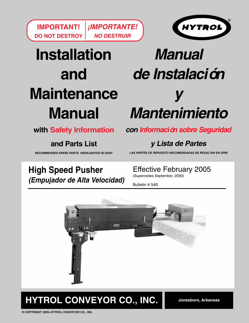
Effective February 2005(Supercedes September, 2000)
Bulletin # 540
I n s t a l l a t i o na n d
M a i n t e n a n c eM a n u a l
with Safety Information
and Parts ListRECOMMENDED SPARE PARTS HIGHLIGHTED IN GRAY
IMPORTANT!DO NOT DESTROY
HYTROL CONVEYOR CO., INC.© COPYRIGHT 2005–HYTROL CONVEYOR CO., INC.
Jonesboro, Arkansas
¡IMPORTANTE!NO DESTRUIR
M a n u a lde Instalación
yM a n t e n i m i e n t o
con Información sobre Seguridad
y Lista de PartesLAS PARTES DE REPUESTO RECOMENDADAS SE RESALTAN EN GRIS
High Speed Pusher(Empujador de Alta Velocidad)
2
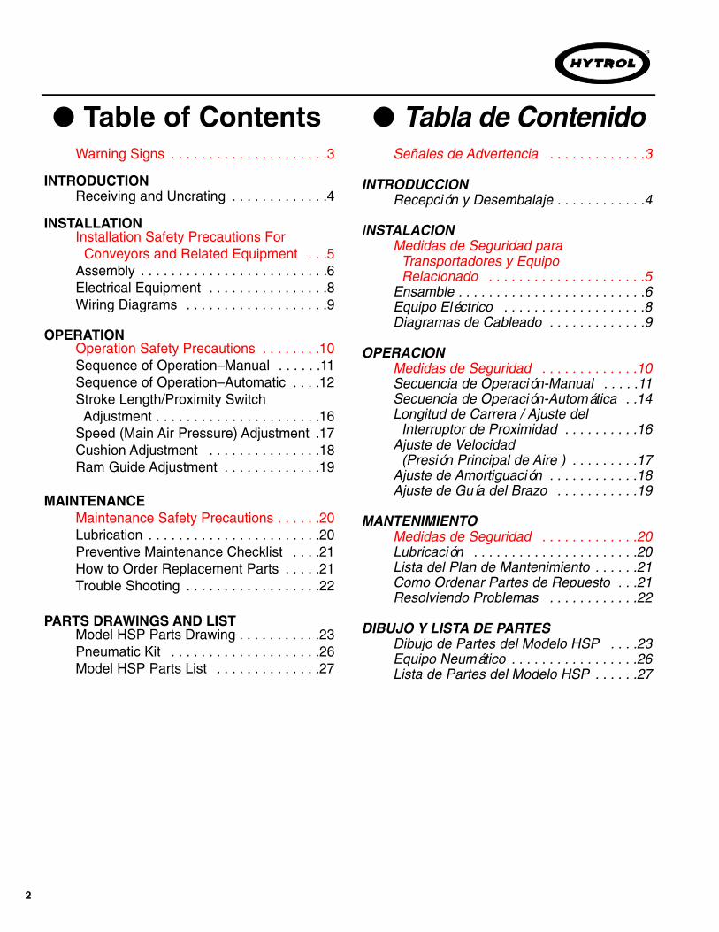
● Table of ContentsWarning Signs . . . . . . . . . . . . . . . . . . . . .3
INTRODUCTIONReceiving and Uncrating . . . . . . . . . . . . .4
INSTALLATIONInstallation Safety Precautions For
Conveyors and Related Equipment . . .5Assembly . . . . . . . . . . . . . . . . . . . . . . . . .6Electrical Equipment . . . . . . . . . . . . . . . .8Wiring Diagrams . . . . . . . . . . . . . . . . . . .9
OPERATIONOperation Safety Precautions . . . . . . . .10Sequence of Operation–Manual . . . . . .11Sequence of Operation–Automatic . . . .12Stroke Length/Proximity Switch
Adjustment . . . . . . . . . . . . . . . . . . . . . .16Speed (Main Air Pressure) Adjustment .17Cushion Adjustment . . . . . . . . . . . . . . .18Ram Guide Adjustment . . . . . . . . . . . . .19
MAINTENANCEMaintenance Safety Precautions . . . . . .20Lubrication . . . . . . . . . . . . . . . . . . . . . . .20Preventive Maintenance Checklist . . . .21How to Order Replacement Parts . . . . .21Trouble Shooting . . . . . . . . . . . . . . . . . .22
PARTS DRAWINGS AND LISTModel HSP Parts Drawing . . . . . . . . . . .23Pneumatic Kit . . . . . . . . . . . . . . . . . . . .26Model HSP Parts List . . . . . . . . . . . . . .27
Señales de Advertencia . . . . . . . . . . . . .3
INTRODUCCIONRecepción y Desembalaje . . . . . . . . . . . .4
INSTALACIONMedidas de Seguridad para
Transportadores y Equipo Relacionado . . . . . . . . . . . . . . . . . . . . .5
Ensamble . . . . . . . . . . . . . . . . . . . . . . . . .6Equipo Eléctrico . . . . . . . . . . . . . . . . . . .8Diagramas de Cableado . . . . . . . . . . . . .9
OPERACIONMedidas de Seguridad . . . . . . . . . . . . .10Secuencia de Operación-Manual . . . . .11Secuencia de Operación-Automática . .14Longitud de Carrera / Ajuste del
Interruptor de Proximidad . . . . . . . . . .16Ajuste de Velocidad
(Presión Principal de Aire ) . . . . . . . . .17Ajuste de Amortiguación . . . . . . . . . . . .18Ajuste de Guía del Brazo . . . . . . . . . . .19
MANTENIMIENTOMedidas de Seguridad . . . . . . . . . . . . .20Lubricación . . . . . . . . . . . . . . . . . . . . . .20Lista del Plan de Mantenimiento . . . . . .21Como Ordenar Partes de Repuesto . . .21Resolviendo Problemas . . . . . . . . . . . .22
DIBUJO Y LISTA DE PARTES Dibujo de Partes del Modelo HSP . . . .23Equipo Neumático . . . . . . . . . . . . . . . . .26Lista de Partes del Modelo HSP . . . . . .27
● Tabla de Contenido
3
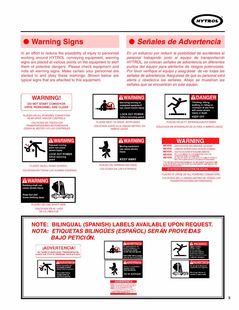
In an effort to reduce the possibility of injury to personnelworking around HYTROL conveying equipment, warningsigns are placed at various points on the equipment to alertthem of potential dangers. Please check equipment andnote all warning signs. Make certain your personnel arealerted to and obey these warnings. Shown below aretypical signs that are attached to this equipment.
En un esfuerzo por reducir la posibilidad de accidentes alpersonal trabajando junto al equipo de transportaciónHYTROL, se colocan señales de advertencia en diferentespuntos del equipo para alertarlos de riesgos potenciales.Por favor verifique el equipo y asegúrese de ver todas lasseñales de advertencia. Asegúrese de que su personal estéalerta y obedezca las señales. Abajo se muestran lasseñales que se encuentran en este equipo.
● Warning Signs ● Señales de Advertencia
PLACED ON ALL POWERED CONVEYORSNEAR DRIVE AND/OR CONTROLS.
PLACED NEXT TO DRIVE, BOTH SIDES. PLACED ON 20 FT. INTERVALS,BOTH SIDES.
PLACED AT DRIVE OF ALL POWERED CONVEYORS.
PLACED ON TERMINATING ENDS.
COLOCADA EN TODOS LOSTRANSPORTADORES MOTORIZADOS
CERCA AL MOTOR Y/O LOS CONTROLES
COLOCADA EN LA UNIDAD MOTRIZ DE TODOS LOSTRANSPORTADORES MOTORIZADOS.
COLOCADA EN INTERVALOS DE 20 PIES, A AMBOS LADOS.
COLOCADA EN LOS EXTREMOS.
COLOCADA JUNTO A LA UNIDAD MOTRIZ, ENAMBOS LADOS.
PLACED ON ALL CHAIN GUARDS.
COLOCADA EN TODAS LAS GUARDA CADENAS.
PLACED ON LINE SHAFT SIDE.
COLOCADA EN EL LADODE LA LÍNEA EJE.
NOTE: BILINGUAL (SPANISH) LABELS AVAILABLE UPON REQUEST.NOTA: ETIQUETAS BILINGÜES (ESPAÑOL) SERÁN PROVEÍDAS
BAJO PETICIÓN.
4
This manual provides guidelines and procedures forinstalling, operating, and maintaining your high speedp u s h e r. A complete parts list is provided withrecommended spare parts highlighted in gray. Importantsafety information is also provided throughout themanual.
For safety to personnel and for proper operation of yourpusher, it is recommended that you read and follow theinstructions provided in this manual.
Check the number of items received against thebill of lading.Examine condition of equipment to determine ifany damage occurred during shipment.Move all crates to area of installation.Remove crating and check for optional equipmentthat may be fastened to the equipment. Make surethese parts (or any foreign pieces) are removed.
1. . .
2. . .
3. . .4. . .
NOTE: If damage has occurred or freight ismissing, see the “Important Notice” attached tothe crate.
I N T R O D U C T I O N I N T R O D U C C I O N
● Receiving and Uncrating
Este manual provee las pautas y los procedimientospara instalar, operar y mantener su empujador de altavelocidad. Se proporciona una lista completa de partes,con partes de repuesto recomendadas que se resaltanen gris. También se proporciona información importantede seguridad a lo largo de este manual. Para seguridaddel personal y para un funcionamiento apropiado delempujador de alta velocidad, se recomienda que lean ysigan las instrucciones proporcionadas en este manual.
N O TA: Si algún daño ha ocurrido o faltacargamento, vea las “Notas Importantes”adheridas al embalaje.
● Recepción y Desembalaje
Verifique el número de partes recibidas con respectoal conocimiento de embarque.Examine las condiciones del equipo con el fin dedeterminar si algún daño ha ocurrido durante eltransporte.Traslade todo el equipo al área de instalación.Remueva todos los empaques y verifique si haypartes opcionales que puedan estar atadas alequipo. Asegúrese de que estas partes (u otraspartes externas) sean removidas.
1. . .
2. . .
3. . .4. . .
5
GUARDS AND GUARDINGInterfacing of Equipment. When two or more pieces ofequipment are interfaced, special attention shall be givento the interfaced area to insure the presence of adequateguarding and safety devices.Guarding Exceptions. Wherever conditions prevail thatwould require guarding under these standards, but suchguarding would render the conveyor unusable,prominent warning means shall be provided in the areaor on the equipment in lieu of guarding.Guarded by Location or Position. Where necessary forthe protection of employees from hazards, all exposedmoving machinery parts that present a hazard toemployees at their work station shall be mechanically orelectrically guarded, or guarded by location or position.
When a conveyor passes over a walkway, roadway,or work station, it is considered guarded solely bylocation or position if all moving parts are at least 8 ft.(2.44 m) above the floor or walking surface or areotherwise located so that the employee cannotinadvertently come in contact with hazardous movingparts.
Although overhead conveyors may be guarded bylocation, spill guard, pan guards, or equivalent shall beprovided if the product may fall off the conveyor for anyreason and if personnel would be endangered.
HEADROOMWhen conveyors are installed above exit passageways,aisles, or corridors, there shall be provided a minimumclearance of 6 ft. 8 in. (2.032 m) measured vertically fromthe floor or walking surface to the lowest part of theconveyor or guards.
Where system function will be impaired by providingthe minimum clearance of 6 ft. 8 in. (2.032 m) through anemergency exit, alternate passageways shall beprovided.It is permissible to allow passage under conveyors withless than 6 ft. 8 in. (2.032 m) clearance from the floor forother than emergency exits if a suitable warningindicates low headroom.
INSTALLATION INSTALACION
● Medidas de Seguridad al I n s t a l a r
Transportadores y Equipos Relacionados
GUARDAS Y PROTECCIONES Unión del Equipo. Cuando dos o más piezas del equipovan unidas, debe ponerse especial atención al área deunión para asegurar que las guardas adecuadas y losdispositivos de seguridad estén presentes.Excepciones de Protección. Dondequiera que lasguardas sean necesarias, pero que la colocación de lasmismas inhabilite el uso del transportador, seproporcionarán señales de advertencia visibles en elárea o en el equipo en vez de las guardas.Protección dada por Posición o Ubicación. Cuandosea necesaria la protección de los empleados contraposibles riesgos, todas las partes del equipo que esténexpuestas y en movimiento, y que puedan presentar unpeligro para ellos en sus puestos de trabajo, seránprotegidas mecánica o eléctricamente, o protegidas porsu posición o ubicación.Cuando el transportador está instalado sobre pasillos,corredores o puestos de trabajo, se considera que estáprotegido únicamente por localización o posición sitodas las partes en movimiento están mínimo a 8 pies(2.44m) de altura del piso, o si está localizado de talmanera que el empleado no pueda entrar en contactoinadvertidamente con dichas partes.A pesar de que los transportadores aéreos pueden estarprotegidos por localización, guardas laterales einferiores deben ser proporcionadas para evitar que elproducto se caiga del transportador y así mantener alpersonal fuera de peligro.
UBICACION SUPERIORCuando los transportadores son instalados sobrepasillos o corredores de salida, debe dejarse un espaciolibre de mínimo 6 pies 8 pulgadas (2,032m), medidoverticalmente desde el piso o área de tránsito hasta laparte más baja del transportador o de las guardas.Si se proporcionan señales de advertencia adecuadasindicando baja altura, es posible dejar espacio libre conmenos de 6 pies 8 pulgadas (2,032m) entre el piso y eltransportador en los pasillos que no sean salidas deemergencia.
● Installation SafetyP r e c a u t i o n s
for Conveyors and Related Equipment

6
● Assembly
Determine location of pusher by finding center lineof take-away conveyor. (Figure 7B).Fasten mounting angles to conveyor frame asshown in Figure 7B. NOTE: If pusher is mounting to138-SP or 190-SP conveyors, spacers are suppliedto locate mounting angles below the line shaftguard. (Figure 7A, Detail “A”).Attach rear support to spacer channels on rear ofpusher (Figure 7A). Preset support to same heightas conveyor supports.Set pusher in place with front support spacer restingon mounting angles. Fasten with 3/8 in. bolts.(Figure 7A).Lag rear support to floor.Pull ram out so ram face is above the oppositechannel from the pusher. Adjust rear support sothere is approximately one inch clearance betweenthe bottom of ram face and the conveying surface.
1. . .
2. . .
3. . .
4. . .
5. . .6. . .
The High Speed Pusher comes completely assembledexcept for installing supports, connecting air andelectrical supply, and mounting to conveyor.
If pusher is to be mounted to a new conveyor, installconveyor as described in the installation andmaintenance manual for the conveyor.
Instructions for installing the pusher are as follows:
MOUNTING TO CONVEYOR
Connect main air line to FRL (Filter / Regulator /Lubricator). Figure 7C.Set working pressure on main regulator and cushionregulator as described in the speed adjustment(main air) and cushion adjustment instructions onPage 17.NOTE: See Packing Envelope for maintenanceinstructions on How To Adjust and Lubricate theFRL.
7. . .
8. . .
Install electrical controls and connect to controlboxes. See Pages 8 and 9. (Also, see inside theconduit box.)
9. . .
AIR SUPPLY
ELECTRICAL
● Ensamble
Encuentre la línea central del transportador paradeterminar la ubicación del empujador. (Figura 7B).Asegure los ángulos de montaje al canal deltransportador como se muestra en la Figura 7B.N O TA: Si el empujador es instalado entransportadores Modelo 138-SP o 190-SP, seproporcionan espaciadores para ubicar los ángulosde montaje debajo de la guarda del eje lineal.(Figura 7A, Detalle "A").Fije el soporte trasero a los canales espaciadoresen la parte trasera del empujador. (Figura 7A).Ajuste previamente el soporte a la misma altura delos soportes del transportador.Ubique el empujador en su lugar, con el espaciadordel soporte delantero descansando sobre losángulos de montaje. Asegure con tornillos de 3/8".(Figura 7A).Ancle el soporte trasero al piso.Saque el brazo del empujador de manera que laparte delantera del brazo quede por encima delcanal opuesto al empujador. Ajuste el soportetrasero de manera que quede aproximadamenteuna pulgada de espacio entre la base del brazo y lasuperficie de transportación.
1. . .
2. . .
3. . .
4. . .
5. . .6. . .
El Empujador de Alta Velocidad viene completamenteensamblado con excepción de los soportes, lasconexiones a las fuentes eléctricas y de aire, y elmontaje al transportador.
Si el Empujador va a ser instalado en un transportadornuevo, instale el transportador como se describe en supropio manual de instalación y mantenimiento.Las instrucciones para instalar el empujador son lassiguientes:
MONTAJE AL TRANSPORTADOR
Conecte la línea principal de aire al FRL (Filtro /Regulador / Lubricador). Figura 7C.Fije la presión de trabajo en el regulador principal yamortigue el regulador como se describe en lasinstrucciones de ajuste de velocidad (suministroprincipal de aire) y ajuste de amortiguación en laPágina 17.Nota: Vea el Sobre de Empaque parainstrucciones de mantenimiento sobre ComoAjustar y Lubricar el FRL.
7. . .
8. . .
Instale los controles eléctricos y conéctelos a lascajas de controles. Vea páginas 8 y 9. (Vea tambiénel interior de la caja del conductor).
9. . .
SUMINISTRO DE AIRE
ELECTRICOS

7
FIGURE 7A
FIGURE 7B FIGURE 7C

● Electrical Equipment
CONTROLS
Electrical Code: All motor controls and wiring shall conformto the National Electrical Code (Article 670 or otherapplicable articles) as published by the National FireProtection Association and as approved by the AmericanStandards Institute, Inc.
CONTROL STATIONS
A) Control stations should be so arranged and located thatthe operation of the equipment is visible from them, andshall be clearly marked or labeled to indicate the functioncontrolled.
SAFETY DEVICES
A) All safety devices, including wiring of electrical safetydevices, shall be arranged to operate in a “Fail-Safe”manner, that is, if power failure or failure of the device itselfwould occur, a hazardous condition must not result.
B) Emergency Stops and Restarts. Conveyor controls shallbe so arranged that, in case of emergency stop, manualreset or start at the location where the emergency stop wasinitiated, shall be required of the conveyor(s) andassociated equipment to resume operation.
C) Before restarting a conveyor which has been stoppedbecause of an emergency, an inspection of the conveyorshall be made and the cause of the stoppage determined.The starting device shall be locked out before any attemptis made to remove the cause of stoppage, unless operationis necessary to determine the cause or to safely remove thestoppage.
Refer to ANSI Z244.1-1982, American National Standard forPersonnel Protection – Lockout/Tagout of Energy Sources –Minimum Safety Requirements and OSHA S t a n d a r dNumber 29 CFR 1910.147 “The Control of HazardousEnergy (Lockout/Tagout).”
WARNING!Electrical controls shall be installed and wired by aqualified electrician. Wiring information for the motorand controls are furnished by the equipmentmanufacturer.
¡ADVERTENCIA!Los controles eléctricos deben ser conectados einstalados por un electricista calificado. La informaciónsobre el cableado del motor y los controles seráproporcionada por el fabricante del equipo.
C O N T R O L E S
Código Eléctrico: Todo Equipo Eléctrico y las conexionesdeben ajustarse al “National Electrical Code” (Artículo 670 uotros artículos aplicables) como fue publicado por la“National Fire Protection Association” y aprobado por el “American Standards Institute, Inc”.
E S TACIONES DE CONTROL
A) Las estaciones de control deberán estar arregladas yubicadas en lugares donde el funcionamiento del equipo seavisible y deberán estar claramente marcadas o señaladaspara indicar la función controlada.
DISPOSITIVOS DE SEGURIDAD
A ) Todos los dispositivos de seguridad, incluyendo la co-nexión de dispositivos eléctricos, deben estar dispuestospara operar en una manera de “autoprotección”; es decir, sise presenta una pérdida de corriente o un fallo en el mismodispositivo, esto no debe resultar en una situación peligrosa.
B ) Paradas de Emergencia y Reactivadores. Los controlesdel transportador deberán estar dispuestos de tal maneraque, en caso de una parada de emergencia, se requiera unactivador o un arrancador manual en el lugar donde laparada de emergencia se presente para reanudar laoperación del transportador o transportadores y el equipoa s o c i a d o .
C) Antes de reiniciar un transportador que ha sido detenidopor una emergencia, debe realizarse una revisión deltransportador y determinarse la causa de la parada. Eldispositivo de arranque deberá ser bloqueado antes deintentar corregir el problema, a no ser que la operación deltransportador sea necesaria para determinar la causa de laparada o para solucionar el problema.
Refiérase al ANSI Z244.1-1982, American National Standardfor Personnel Protection - Lockout/Tagout of Energy Sources- Minimum Safety Requirements and OSHA S t a n d a r dNumber 29 CFR 1910.147 “The Control of HazardousEnergy (Lockout/Ta g o u t ) . ”
● Equipo Eléctrico
8

9
STANDARD AC POWER SUPPLY(120 Volt-60 Hz.-Single Phase)
(FUENTE DE PODER ESTANDAR AC)[120 Volt-60 Hz.-Una Fase]
NOTE: CONTACT “X” REQUIRES 150-200 MILLISECOND CLOSED TIME (NOT SUPPLIED).
NOTA: SE REQUIERE UN TIEMPO DE CONTACTO EN “X” DE 150-200 MILISEGUNDOS
STANDARD CONNECTIONAS WIRED AT FACTORY
(CONEXION ESTANDARREALIZADA EN LA FABRICA)
MODIFIED FOR PLC CONTROL WITHHOME POSITION PROXIMITY SWITCH
(CONEXION MODIFICADA PARA CONTROL PLCCON INTERRUPTOR DE PROXIMIDAD EN LA
POSICION DE RETRACCION)
FIGURE 9A FIGURE 9B
● Wiring Diagrams ● Diagramas de Cableado
10
OPERATION OPERACION
● Operation SafetyPrecautions
● Medidas de Seguridad en la Operación
A) Only trained employees shall be permitted to operateconveyors. Training shall include instruction in operationunder normal conditions and emergency situations.
B) Where employee safety is dependent upon stoppingand/or starting devices, they shall be kept free ofobstructions to permit ready access.
C) The area around loading and unloading points shallbe kept clear of obstructions which could endangerpersonnel.
D) A conveyor shall be used to transport only material itis capable of handling safely.
E ) Under no circumstances shall the safetycharacteristics of the conveyor be altered if suchalterations would endanger personnel.
F) Routine inspections and preventive and correctivemaintenance programs shall be conducted to insure thatall safety features and devices are retained and functionproperly.
A) Solo se deberá permitir operar los transportadores aempleados entrenados. El entrenamiento debe incluirinstrucciones de operación bajo condiciones normales yen situaciones de emergencia.
B) Cuando la seguridad de los trabajadores depende dedispositivos de parada y/o arranque, tales dispositivosdeben mantenerse libres de obstrucciones para permitirun acceso rápido.
C) El área alrededor de los puntos de carga y descargadeberá mantenerse libre de obstrucciones, las cualespodrían poner en peligro al personal.
D) Un transportador deberá ser utilizado para transportarsolamente los productos que sea capaz de manejar enforma segura.
E) Bajo ninguna circunstancia deberán ser alteradas lascaracterísticas de seguridad de un transportador si talesalteraciones pudieran poner en peligro al personal.
F) Inspecciones rutinarias deberán llevarse a cabo aligual que programas de mantenimiento preventivo ycorrectivo, con el fin de asegurar que todos losdispositivos y medidas de seguridad se conserven enbuen estado y funcionen correctamente.

11
● Sequence of Operation–M A N U A L
WARNING!Make sure all personnel are clear of ramarea during operation. Also, remove anyforeign objects that could damage pusherfrom this area.
Prior to automatic operation, the high speed pushershould be manually cycled to see that it is operatingfreely in both directions and that the speed and cushionfeatures have been adjusted properly. A test switch(Figure 11A) mounted to the conduit box is provided forthis purpose.
Read the instructions on Pages 17 and 18 on HowTo Adjust the Speed and Cushion Features.Cycle pusher by moving the toggle switch to the“test” position. NOTE: Do not hold in thisposition–Release switch as soon as pusherbegins cycle.Observe operation and make necessaryadjustments as described in the adjustmentinstructions.
1. . .
2. . .
3. . .
The 3-Position Selector Switch switch also has a“reset” position. If, because of an incorrectadjustment of main air pressure, cushion airpressure, flow control valve, etc., the ram jams in apartially extended position, moving the 3-PositionSelector Switch to “reset” will cause the ram to fullyretract.
4. . .
TEST (To Manually Cycle Pusher)
RESET
FIGURE 11A
CONDUIT BOX(CAJA DEL CONDUCTOR)
THREE POSITION SELECTOR SWITCH(INTERRUPTOR SELECTOR DE
TRES POSICIONES)
OPERATION OPERACION
● Secuencia de Operación- M A N U A L
Antes de la operación automática, el empujador de altavelocidad debe ser operado manualmente para revisarque funcione libremente en ambas direcciones y que lascaracterísticas de velocidad y amortiguación hayan sidoajustadas apropiadamente. Un interruptor de prueba(Figura 11A) instalado en la caja del conductor se proveepara este propósito.
1. . .
2. . .
3. . .
4. . .
¡ADVERTENCIA!Asegúrese que todo el personal estealejado del área del brazo durante la
operación. Además, remueva del áreacualquier objeto extraño que pudiera
dañar el empujador.
Lea las instrucciones en la páginas 17 y 18 acercade Como Ajustar las Características de Velocidad yAmortiguación.Iniciar la operación del empujador moviendo elinterruptor de palanca a la posición "prueba" (Test).N O TA: No mantenga el interruptor en estaposición. Suéltelo tan pronto como elempujador empiece a operar.Observe la operación y haga los ajustes necesarioscomo se describe en las instrucciones de ajuste.
El interruptor selector de tres posiciones cuentatambién con una posición de "reinicio" (Reset). Si elbrazo se atasca en una posición de parcialextensión como consecuencia de un ajusteincorrecto de la presión de aire principal, de lapresión de aire de amortiguación, de la válvula decontrol de flujo, etc., se debe mover el interruptorselector de tres posiciones a "reinicio" para que elbrazo se retraiga completamente.
PRUEBA (Para Operar Manualmente elEmpujador)
REINICIAR
(REINICIAR) (PRUEBA)
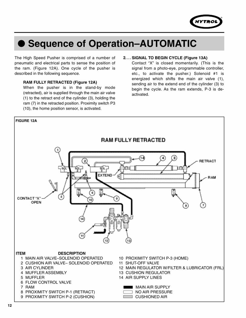
10 PROXIMITY SWITCH P-3 (HOME)11 SHUT-OFF VALVE12 MAIN REGULATOR W/FILTER & LUBRICATOR (FRL) 13 CUSHION REGULATOR14 AIR SUPPLY LINES
MAIN AIR SUPPLYNO AIR PRESSURECUSHIONED AIR
12
● Sequence of Operation–AUTOMATICThe High Speed Pusher is comprised of a number ofpneumatic and electrical parts to sense the position ofthe ram. (Figure 12A). One cycle of the pusher isdescribed in the following sequence.
FIGURE 12A
RAM FULLY RETRACTED (Figure 12A)When the pusher is in the stand-by mode(retracted), air is supplied through the main air valve(1) to the retract end of the cylinder (3), holding theram (7) in the retracted position. Proximity switch P3(10), the home position sensor, is activated.
SIGNAL TO BEGIN CYCLE (Figure 13A)Contact “X” is closed momentarily. (This is thesignal from a photo-eye, programmable controller,etc., to activate the pusher.) Solenoid #1 isenergized which shifts the main air valve (1),sending air to the extend end of the cylinder (3) tobegin the cycle. As the ram extends, P-3 is de-activated.
2. . .
ITEM DESCRIPTION1 MAIN AIR VALVE–SOLENOID OPERATED2 CUSHION AIR VALVE– SOLENOID OPERATED 3 AIR CYLINDER4 MUFFLER ASSEMBLY5 MUFFLER6 FLOW CONTROL VALVE7 RAM 8 PROXIMITY SWITCH P-1 (RETRACT)9 PROXIMITY SWITCH P-2 (CUSHION)

13
● Sequence of Operation–AUTOMATIC
CAUTION!The activation signal must be a pulse of nomore than 200 milliseconds. A longer signalwill override the retract signal given by P-1,allowing the ram to overextend and “bottom-out”, possibly damaging the cylinder.
FIGURE 13A
FIGURE 13B
FIGURE 13C
BEGINNING OF RETRACT STROKE (Figure 13B)As the ram nears the end of the extend stroke, itactivates P-1 (8), which in turn activates solenoid #2of the main air valve. Air is shifted from the extendend of the cylinder to the retract end, causing theram to begin the retract stroke. (The ram is reversedbefore the cylinder is fully extended to cushion thestroke.)
END OF RETRACT STROKE (Figure 13C)As the ram approaches the end of the retract stroke,it activates P-2 (9), which in turn activates solenoid#3 of the cushion air valve (2). This sends a burst ofair into the extend end of the cylinder, cushioningthe impact of the ram as it returns to the fullyretracted position. NOTE: Some of the cushion air isallowed to exhaust through the main air valve andthrough a flow control valve (6), which allows thecushioning action to be adjusted for properoperation.
3. . .
4. . .
The above sequence is for the pusher as it iswired at the factory. (See Wiring Diagram onPage 9–Figure 9A). In this configuration P-3, thehome position sensor, is wired in series with thetest switch, and is used to override theactivation signal, to insure the signal is a pulse.If the test switch is held closed, the pusher willcontinue to cycle.
The pusher may be re-wired to bypass P-3,which can then be used to signal aprogrammable controller or other device whenthe ram is fully retracted. (See Figure 9B).
1. . .
2. . .
NOTES:
14
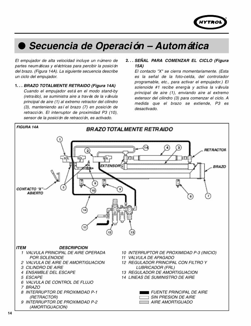
● Secuencia de Operación – AutomáticaEl empujador de alta velocidad incluye un número departes neumáticas y eléctricas para percibir la posicióndel brazo. (Figura 14A). La siguiente secuencia describeun ciclo del empujador.
FIGURA 14A
BRAZO TOTALMENTE RETRAIDO (Figura 14A)Cuando el empujador está en el modo stand-by(retraído), se suministra aire a través de la válvulaprincipal de aire (1) al extremo retractor del cilindro(3), manteniendo así el brazo (7) en posición deretracción. El interruptor de proximidad P3 (10),sensor de la posición de retracción, es activado.
1. . .
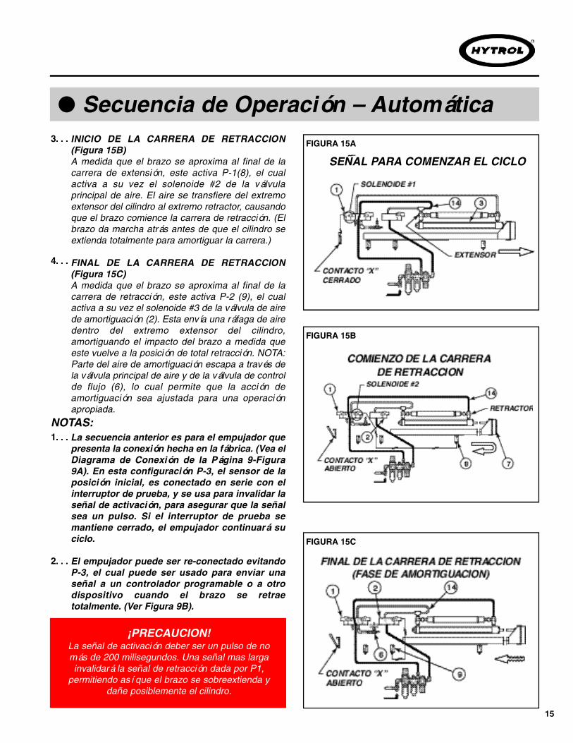
SEÑAL PARA COMENZAR EL CICLO (Figura15A)El contacto "X" se cierra momentariamente. (Estaes la señal de la foto-celda, del controladorprogramable, etc., para activar el empujador.) Elsolenoide #1 recibe energía y activa la válvulaprincipal de aire (1), enviando aire al extremoextensor del cilindro (3) para comenzar el ciclo. Amedida que el brazo se extiende, P3 esdesactivado.
2. . .
10 INTERRUPTOR DE PROXIMIDAD P-3 (INICIO)11 VALVULA DE APAGADO12 REGULADOR PRINCIPAL CON FILTRO Y
LUBRICADOR (FRL) 13 REGULADOR DE AMORTIGUACION14 LINEAS DE SUMINISTRO DE AIRE
FUENTE PRINCIPAL DE AIRESIN PRESION DE AIREAIRE AMORTIGUADO
ITEM DESCRIPCION1 VALVULA PRINCIPAL DE AIRE OPERADA
POR SOLENOIDE2 VALVULA DE AIRE DE AMORTIGUACION 3 CILINDRO DE AIRE4 ENSAMBLE DEL ESCAPE5 ESCAPE6 VALVULA DE CONTROL DE FLUJO7 BRAZO 8 INTERRUPTOR DE PROXIMIDAD P-1
(RETRACTOR)9 INTERRUPTOR DE PROXIMIDAD P-2
(AMORTIGUACION)
15
● Secuencia de Operación – Automática
¡PRECAUCION!La señal de activación deber ser un pulso de nomás de 200 milisegundos. Una señal mas largainvalidará la señal de retracción dada por P1,
permitiendo así que el brazo se sobreextienda ydañe posiblemente el cilindro.
FIGURA 15A
FIGURA 15B
FIGURA 15C
INICIO DE LA C A R R E R A DE RETRACCION(Figura 15B)A medida que el brazo se aproxima al final de lacarrera de extensión, este activa P-1(8), el cualactiva a su vez el solenoide #2 de la válvulaprincipal de aire. El aire se transfiere del extremoextensor del cilindro al extremo retractor, causandoque el brazo comience la carrera de retracción. (Elbrazo da marcha atrás antes de que el cilindro seextienda totalmente para amortiguar la carrera.)
F I N A L DE LA C A R R E R A DE RETRACCION(Figura 15C)A medida que el brazo se aproxima al final de lacarrera de retracción, este activa P-2 (9), el cualactiva a su vez el solenoide #3 de la válvula de airede amortiguación (2). Esta envía una ráfaga de airedentro del extremo extensor del cilindro,amortiguando el impacto del brazo a medida queeste vuelve a la posición de total retracción. NOTA:Parte del aire de amortiguación escapa a través dela válvula principal de aire y de la válvula de controlde flujo (6), lo cual permite que la acción deamortiguación sea ajustada para una operaciónapropiada.
3. . .
4. . .
La secuencia anterior es para el empujador quepresenta la conexión hecha en la fábrica. (Vea elDiagrama de Conexión de la Página 9-Figura9A). En esta configuración P-3, el sensor de laposición inicial, es conectado en serie con elinterruptor de prueba, y se usa para invalidar laseñal de activación, para asegurar que la señalsea un pulso. Si el interruptor de prueba semantiene cerrado, el empujador continuará suciclo.
El empujador puede ser re-conectado evitandoP-3, el cual puede ser usado para enviar unaseñal a un controlador programable o a otrodispositivo cuando el brazo se retraetotalmente. (Ver Figura 9B).
1. . .
2. . .
NOTAS:
SEÑAL PARA COMENZAR EL CICLO

16
● Stroke Length/Proximity Switch Adjustment
The High Speed Pusher is available in three strokelength ranges: 14"-18", 18"-24", and 24"-30". The strokelength may be set at any point within the range of eachmodel. Stroke may be varied by adjusting the extendproximity switch (P-1). This procedure, as well as otheradjustments required to set the proximity switches, aredescribed below.
FIGURE 16A
Loosen the four switch bracket mounting boltsslightly. NOTE: It is not necessary to remove thebottom guard. (See Figure 16A).Slide the switch bracket in the slots in the pusherbed to adjust stroke: toward conveyor to increasestroke, away from conveyor to decrease.To check stroke setting, cycle the pusher by usingthe test switch. If further adjustment is needed,repeat Step 2.Tighten the bracket mounting bolts.
1. . .
2. . .
3. . .
4. . .
FIGURE 16B
STROKE LENGTH ADJUSTMENT (P-1)
The cushion proximity switch (P-2) and the homeposition proximity switch (P-3) are set at the factoryand should not require adjustment. If adjustmentshould become necessary, set the switches asfollows:P-2: set in center of adjustment slots.P-3: set so that the sensor bar is directly over theswitch when the ram is fully retracted.
1. . .
H O R I Z O N TA L ADJUSTMENT (P-2 and P-3)
● Longitud de Carrera / Ajuste del Interruptor de Proximidad
El Empujador de Alta Velocidad está disponible en tresrangos de longitud de carrera: 14"- 18", 18"- 24" y 24"-30". La longitud de carrera se puede fijar en cualquierpunto dentro del rango de cada modelo. Esta se puedemodificar mediante el ajuste del interruptor deproximidad del extensor (P-1). Este procedimiento, comootros ajustes requeridos en los interruptores deproximidad se describen a continuación.
Afloje un poco los cuatro tornillos de la placa demontaje del interruptor. NOTA: No es necesarioremover la guarda inferior. (Ver Figura 16A).Deslice la placa de interruptor en las ranuras de lacama del empujador para ajustar la carrera: hacia eltransportador para aumentar la carrera yalejándose del transportador para disminuirla.Para revisar el ajuste de la carrera, opere elempujador usando el interruptor de prueba. Si serequiere un ajuste adicional, repita el Paso 2. Apriete los tornillos de la placa de montaje.
1. . .
2. . .
3. . .
4. . .
AJUSTE DE LA LONGITUD DE CARRERA ( P - 1 )
El interruptor de proximidad de Amortiguación (P-2)y el interruptor de proximidad de Inicio (P-3) soninstalados en la fábrica y no deben requerir ajuste.Si es necesario realizar un ajuste, instale losinterruptores como sigue:P-2: colóquelo en el centro de las ranuras de ajuste.P-3: colóquelo de manera que la barra sensoraquede directamente sobre el interruptor cuando elbrazo se retrae totalmente.
1. . .AJUSTE HORIZONTA L (P-2 y P-3)

17
Close air supply valve and disconnect power supply.Remove bottom guard. NOTE: The guard is heldin place by 1/4-turn fasteners. Do not turn morethan necessary to release guard!Manually position the ram so that the sensor bar isdirectly above the switch.Loosen the jam nuts on the switch. Position theswitch so that there is a 1/4" gap between the switchand the sensor bar. (Figure 16B). Tighten the jamnuts securely.
1. . .
2. . .
3. . .
V E R T I C A L ADJUSTMENT (ALL S W I T C H E S )Cierre la válvula de aire y desconecte la fuente depoder. Remueva la guarda inferior. NOTA: La guardase sostiene con aseguradores de 1/4. ¡No los gire másde lo necesario para soltar la guarda!Posicione manualmente el brazo de manera que labarra sensora quede directamente sobre el interruptor.Afloje las contratuercas del interruptor. Posicione elinterruptor de manera que quede un espacio de 1/4"entre el interruptor y la barra sensora. (Figura 16B).Apriete las contratuercas firmemente.
1. . .
2. . .
3. . .
● Speed (Main Air Pressure) Adjustment
Pusher speed (cycle time) will vary depending on theweight of the product being pushed. However, speed(and impact force) may be controlled by adjusting themain pressure regulator. The following procedure issuggested to set the proper operating pressure for yourparticular range of product weights. NOTE: Cushionpressure and/or cushion bleed-off must be set afterany main pressure adjustment.
Set pressure at 60 PSI and adjust cushion.Place product on conveyor and operate pusher.a) If pusher “throws” product or causes product totumble, decrease pressure approximately 10 PSI,set cushion, and repeat test.b) Repeat until desired pushing action is achieved.NOTE: Recommended pressure range: 40 to 80PSI.
1. . .2. . .
IF YOUR PRODUCT WEIGHT IS CONSISTENT(± 5 lbs.):
Set pressure at 60 PSI and adjust cushion.Select heaviest product and set pressure asdescribed in Step 2 above. Select the lowestpressure that will push the product at the requiredspeed.Select the lightest product and test. If pushing actionis unacceptable:a) if possible, decrease the difference in productweights. (This applies to order picking operationsusing totes, etc.)b) Vary main pressure as described above to findthe pressure that works best for most productweights.
1. . .2. . .
3. . .
IF YOUR PRODUCT WEIGHT VARIES CONSIDERABLY:
AJUSTE VERT I C A L ( TODOS LOS INTERRUPTO R E S )
● Ajuste de Velocidad (Presión Principal de A i r e )
La velocidad del empujador (tiempo del ciclo) puede variardependiendo del peso del producto a ser empujado. Sinembargo, la velocidad (y la fuerza del impacto) se puedecontrolar ajustando el regulador de presión principal. Serecomienda el siguiente procedimiento para establecer lapresión de operación apropiada para el rango específico depeso de sus productos. N O TA: La presión deamortiguación y/o de descarga de amortiguación sedebe fijar después de cualquier ajuste a la presiónprincipal.
Fije la presión en 60 PSI y ajuste la amortiguación.Coloque el producto sobre el transportador y opere elempujador.a) Si el empujador "arroja" el producto o provoca queel producto ruede, disminuya la presión 10PSIaproximadamente, fije la amortiguación, y repita laprueba.b) Repita hasta que se obtenga la acción de empujedeseada. NOTA: Rango de presión recomendado:40 a 80 PSI.
1. . .2. . .
SI EL PESO DE SU PRODUCTO ES CONSISTENTE (± 5 lbs.):
Fije la presión en 60 PSI y ajuste la amortiguación.Seleccione el producto más pesado y fije la presióncomo se ha descrito previamente en el Paso 2.Seleccione la presión más baja que empuje elproducto a la velocidad requerida.Seleccione el producto más liviano y pruebe. Si laacción de empuje es inaceptable:a) Si es posible, disminuya la diferencia de peso entreproductos. (Esto aplica en operaciones de selecciónde ordenes usando contenedores plásticos, etc.)b) Ajuste la presión principal como se describepreviamente para encontrar la presión que funcionemejor con la mayoría de pesos de los productos.
1. . .2. . .
3. . .
SI EL PESO DE SU PRODUCTO VA R I AC O N S I D E R A B L E M E N T E :

18
● Cushion AdjustmentAs the pusher ram nears the end of the retract stroke, ashort blast of air is applied to the extend end of thecylinder, providing a cushion for the ram as it comes torest. This cushion may be adjusted as follows:
The cushion pressure is controlled by the cushionregulator. In most cases, the cushion pressureshould be set at 20 PSI less than the main regulatorpressure setting. For example, if the main regulatorpressure is set at 60 PSI, this cushion regulatorpressure should be set at 40 PSI.
CUSHION PRESSURE ADJUSTMENT
Adjust flow control knob clockwise until ram comes torest with little or no “bump”, cycle pusher several times tocheck cushion setting.
a) NOT ENOUGH CUSHION (RAM HITS HARD ONRETRACT STROKE):
1. . .
Actual “fine-tuning” of the cushion is accomplishedby varying the amount of cushion air that is allowedto escape through the cushion flow control valve.After setting the main regulator pressure and thecushion regulator pressure, cycle the pusher usingthe test switch, observe the cushioning action, andadjust as described below.
CUSHION “BLEED-OFF” ADJUSTMENT1. . .
Adjust flow control knob counter-clockwise until ram nolonger “bounces”, cycle pusher several times to checkcushion setting.
b) TOO MUCH CUSHION (RAM “BOUNCES” AT ENDOF RETRACT STROKE, MAY REMAIN PARTIALLYEXTENDED):
● Ajuste de A m o r t i g u a c i ó nA medida que el brazo del empujador se aproxima alfinal de la carrera de retracción, una pequeña ráfaga deaire se aplica al extremo extensor del cilindro,proporcionando una amortiguación para el brazo amedida que este regresa a su posición inicial. Esteamortiguamiento puede ser ajustado de la siguientemanera:
La presión de amortiguación es controlada por elregulador de amortiguación. En la mayoría de loscasos, la presión de amortiguación debe fijarse a 20PSI menos que la presión del regulador principal.Por ejemplo, si la presión del regulador principal sefija a 60 PSI, la presión del regulador deamortiguación se debe fijar a 40 PSI.
AJUSTE DE LA PRESION DE AMORTIGUACION
Ajuste la perilla de control de flujo en el sentido de lasmanecillas del reloj hasta que el brazo regrese a su iniciocon un "golpe" muy pequeño o sin ningún "golpe". Opereel empujador varias veces para revisar elamortiguamiento.
a) NO HAY SUFICIENTE A M O RTIGUACION (EL B R A Z OG O L P E A F U E RTE DURANTE LA C A R R E R A D ER E T R A C C I O N ) :
1. . .
El ajuste efectivo de la amortiguación se logravariando la cantidad de aire amortiguador que sedeja escapar a través de la válvula de control delflujo de amortiguación. Después de fijar la presióndel regulador principal y la presión del regulador deamortiguación, opere el empujador usando elinterruptor de prueba, observe la acción deamortiguación y ajústela como se describe acontinuación:
AJUSTE DE LA DESCARGA DE AMORTIGUACION
1. . .
Ajuste la perilla de control de flujo en el sentido opuestoa las manecillas del reloj hasta que el brazo ya norebote. Opere el empujador varias veces para revisar elamortiguamiento.
b) DEMASIADA A M O RTIGUACION (El BRAZO" R E B O TA" A L F I N A L DE LA C A R R E R A D ERETRACCIÓN, Y/O PERMANECE PA R C I A L M E N T EEXTENDIDO):

19
● Ram Guide A d j u s t m e n tThe pusher ram is guided by UHMW wearstrips. Theguides are preset at the factory to provide the properram-to-wearstrip clearance and should not requireadjustment. If the ram becomes excessively loose, or ifthe ram becomes difficult to slide in and out by hand (withair supply valve closed), the following procedure may beused to adjust the guides.
Close air supply valve and disconnect powersupply. Remove bottom guard.Loosen the 4 vertical adjustment bolts and twohorizontal adjustment bolts. (Loosen only the boltsin one side wearstrip support angle. Leave on anglestationary.) (See Figure 19A & 19B).Place 22 ga. (0.033 in.) shims as shown. Raise thewearstrip support brackets until the ram is in contactwith the top and bottom wearstrip (with shims).Tighten vertical adjustment bolts.Hold the side wearstrip support angle so that theram is in contact with the wearstrips on both sides(with shim). Tighten horizontal adjustment bolts.Move the ram to release the shims. Slide the ram inand out by hand. It should move freely withoutexcessive side-to-side or up-and-down movement.
1. . .
2. . .
3. . .
4. . .
5. . .
FIGURE 19A
FIGURE 19B
● Ajuste de la Guía del BrazoEl brazo del empujador es guiado por guías plásticas(wearstrips) UHMW. Las guías son pre-instaladas en lafábrica para proveer el margen apropiado entre el brazoy las guías y no deben requerir ajuste. Si el brazo llegaa quedar excesivamente suelto, o si se vuelve difícildeslizar el brazo hacia adentro y hacia afueramanualmente (con la válvula de aire cerrada), elsiguiente procedimiento puede usarse para ajustar lasguías.
Cierre la válvula de aire y desconecte la fuente depoder. Remueva la guarda inferior.Afloje los 4 tornillos de ajuste vertical y los dos deajuste horizontal. (Afloje solamente los tornillos deun lado del ángulo de soporte de las guías. Dejesobre el ángulo estacionario.) (Ver Figura 19A &19B).Coloque placas de ajuste calibre 22 ga. (0.033")como se muestra. Suba las abrazaderas delsoporte de las guías hasta que el brazo quede encontacto con las guías superior e inferior (conplacas de ajuste). Apriete los tornillos de ajustevertical. Sostenga el soporte angular de la guía lateral demanera que el brazo quede en contacto con lasguías en ambos lados (con placa de ajuste). Aprietelos tornillos de ajuste horizontal.Mueva el brazo para soltar las placas de ajuste.Deslice el brazo hacia adentro y hacia afueramanualmente. Se debe mover libremente sinmovimientos excesivos de lado a lado o de arriba aabajo.
1. . .
2. . .
3. . .
4. . .
5. . .

20
● LubricationAIR LINE LUBRICATORSee Packing Envelope for information from supplier onthe proper lubricant and how to service the air linelubricator.
M A I N T E N A N C E M A N T E N I M I E N TO
A ) Maintenance, such as lubrication and adjustments,shall be performed only by qualified and trained personnel.
B ) It is Important that a maintenance program beestablished to insure that all conveyor components aremaintained in a condition which does not constitute ahazard to personnel.
C ) When a conveyor is stopped for maintenancepurposes, starting devices or powered accessories shall belocked or tagged out in accordance with a formalizedprocedure designed to protect all person or groups involvedwith the conveyor against an unexpected start.
D ) Replace all safety devices and guards before startingequipment for normal operation.
E ) Whenever practical, DO NOT lubricate conveyors whilethey are in motion. Only trained personnel who are awareof the hazard of the conveyor in motion shall be allowed tol u b r i c a t e .
S A F E T Y G U A R D SMaintain all guards and safety devices IN POSITION a n dIN SAFE REPA I R .
WARNING SIGNSMaintain all warning signs in a legible condition and obey allwarnings. See Page 3 of this manual for examples ofwarning signs.
A) El mantenimiento, tal como lubricación y ajustes,deberá ser realizado solamente por personal calificado yentrenado.
B) Es importante que se establezca un programa demantenimiento para asegurar que todos loscomponentes del transportador sean mantenidos encondiciones que no constituyan un peligro para elpersonal.
C) Cuando un transportador está parado por razones demantenimiento, los dispositivos de arranque oaccesorios motorizados deberán ser asegurados odesconectados conforme a un procedimientoformalizado, diseñado para proteger a toda persona ogrupos involucrados con el transportador, de unarranque inesperado.
D ) Antes de poner en marcha el equipo en unaoperación normal, vuelva a colocar todos los dispositivosde seguridad y las guardas.
E ) Siempre que sea práctico, N O lubrique lostransportadores mientras se encuentren en movimiento.Solo el personal entrenado que tenga conocimiento delos peligros del transportador en movimiento, se lepermitirá hacer la lubricación.
PROTECCIONES DE SEGURIDADMantenga todas las guardas y dispositivos de seguridadEN SU POSICION y EN BUENAS CONDICIONES.
SEÑALES DE ADVERTENCIAMantenga todas las señales de advertencia en buenascondiciones y obedézcalas. Remítase a la página 3 deeste manual para ver ejemplos de señales deadvertencia.
● Maintenance SafetyPrecautions
● Medidas de Seguridad en el Mantenimiento
● LubricaciónLUBRICADOR DE LA LINEA DE AIRERemítase al Sobre de Empaque para información delproveedor sobre el lubricante apropiado y sobre comorealizar mantenimiento al lubricador de la línea de aire.

21
● Preventive Maintenance Checklist
Check air pressure in both regulators*, SeeInstructions on Page 17.Check for water in filter* bowl. Drain when waterlevel reaches the lower baffle.Check for excessive noise or vibration duringoperation.
1. . .
2. . .
3. . .
D A I LY
Check oil level in lubricator*. Add oil as needed.Remove cover and check for loose fasteners.Check cylinder rod for dirt build-up. Clean asneeded.
1. . .2. . .3. . .
W E E K LY
Check ram guides for wear. Clean off excess dirtbuild-up. See Page 12 for ram guide adjustment.
1. . .
M O N T H LY
*NOTE: See Packing Envelope for information fromsupplier on How to Service the FRL ( F i l t e r / R e g u l a -t o r / L u b r i c a t o r ) .
● Lista del Plan de M a n t e n i m i e n t o
Revise la presión de aire en ambos *reguladores.Vea instrucciones en la Página 17.Revise el agua en el recipiente del *filtro. Vacíecuando el nivel del agua alcance el punto más bajodel desviador.Revise si se produce ruido o vibración excesivadurante la operación.
1. . .
2. . .
3. . .
D I A R I A M E N T E
Revise el nivel de aceite del *lubricador. Adicioneaceite si se necesita.Remueva la cubierta y revise si hay aseguradoressueltos.Revise si se ha acumulado suciedad en la barra delcilindro. Limpie si es necesario.
1. . .
2. . .
3. . .
S E M A N A L M E N T E
Revise si se han desgastado las guías del brazo.Retire la suciedad que se haya acumulado. Paraajuste de la guía del brazo, vea la Página 12.
1. . .M E N S U A L M E N T E
* N O TA: Remítase al Sobre de Empaque parainformación del proveedor sobre Como RealizarMantenimiento al FRL ( F i l t r o / R e g u l a d o r / L u b r i c a d o r ) .
● How to Order Replacement Parts
Included in this manual is a parts drawing with acomplete replacement parts list. When orderingreplacement parts, please refer to the orderingprocedure below:
Contact Distributor from which equipment wasoriginally purchased or nearest HYTROLDistributor.Provide Distributor with the model and the partdescription and number from Parts List.Advise if you are in a breakdown situation, sofastest possible service is provided.
1. . .
2. . .
3. . .
● Como Ordenar Partes de Repuesto
Dibujos de las partes y listas completas de las partes derepuesto están incluidos en este manual. Cuandoordene partes de repuesto, por favor refiérase alsiguiente procedimiento:
Contacte al Distribuidor que le vendió el equipooriginalmente o al distribuidor de Hytrol máscercano.Proporcione al Distribuidor el modelo y ladescripción de la parte y el número que aparece enla Lista de Partes.Informe si se encuentra en una situación críticapara prestarle el servicio lo más rápido posible.
1. . .
2. . .
3. . .
22
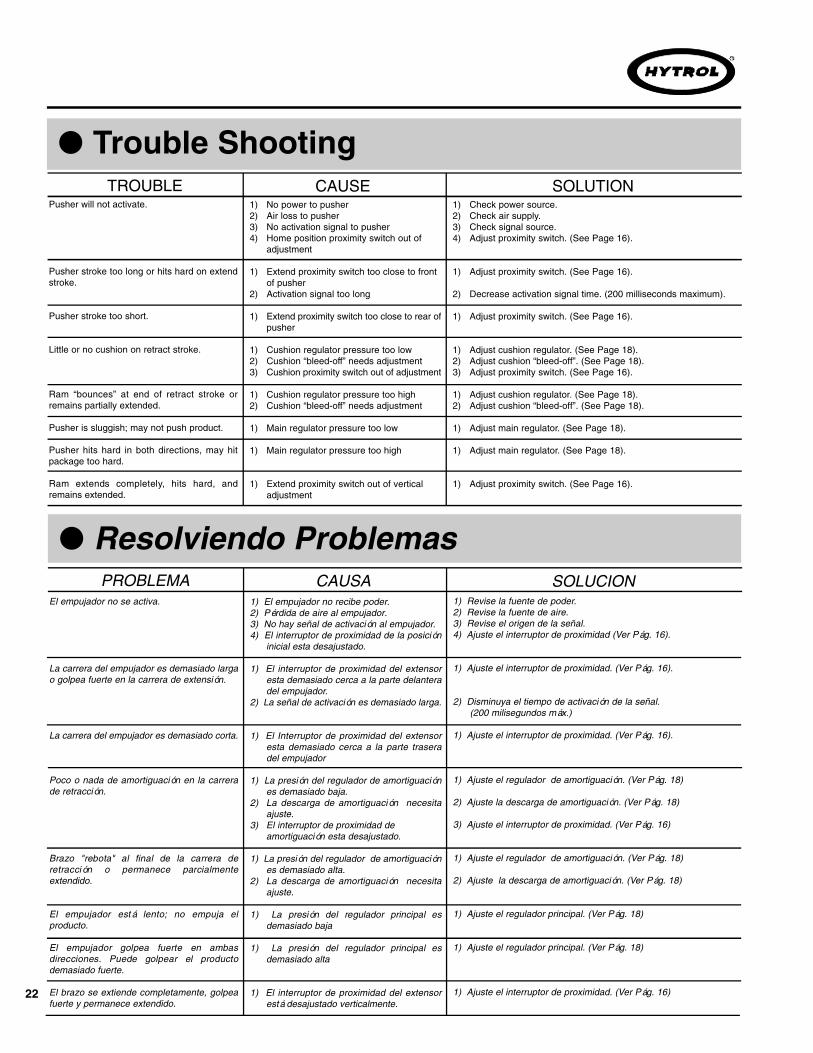
● Trouble ShootingTROUBLE CAUSE SOLUTION
Pusher will not activate.
Pusher stroke too long or hits hard on extendstroke.
Pusher stroke too short.
Little or no cushion on retract stroke.
Ram “bounces” at end of retract stroke orremains partially extended.
Pusher is sluggish; may not push product.
Pusher hits hard in both directions, may hitpackage too hard.
Ram extends completely, hits hard, andremains extended.
1) No power to pusher2) Air loss to pusher3) No activation signal to pusher4) Home position proximity switch out of
adjustment
1) Extend proximity switch too close to front of pusher
2) Activation signal too long
1) Extend proximity switch too close to rear ofpusher
1) Cushion regulator pressure too low2) Cushion “bleed-off” needs adjustment3) Cushion proximity switch out of adjustment
1) Cushion regulator pressure too high2) Cushion “bleed-off” needs adjustment
1) Main regulator pressure too low
1) Main regulator pressure too high
1) Extend proximity switch out of vertical adjustment
1) Check power source.2) Check air supply.3) Check signal source.4) Adjust proximity switch. (See Page 16).
1) Adjust proximity switch. (See Page 16).
2) Decrease activation signal time. (200 milliseconds maximum).
1) Adjust proximity switch. (See Page 16).
1) Adjust cushion regulator. (See Page 18).2) Adjust cushion “bleed-off”. (See Page 18).3) Adjust proximity switch. (See Page 16).
1) Adjust cushion regulator. (See Page 18).2) Adjust cushion “bleed-off”. (See Page 18).
1) Adjust main regulator. (See Page 18).
1) Adjust main regulator. (See Page 18).
1) Adjust proximity switch. (See Page 16).
● Resolviendo ProblemasPROBLEMA CAUSA SOLUCION
El empujador no se activa.
La carrera del empujador es demasiado largao golpea fuerte en la carrera de extensión.
La carrera del empujador es demasiado corta.
Poco o nada de amortiguación en la carrerade retracción.
Brazo "rebota" al final de la carrera deretracción o permanece parcialmenteextendido.
El empujador está lento; no empuja elproducto.
El empujador golpea fuerte en ambasdirecciones. Puede golpear el productodemasiado fuerte.
El brazo se extiende completamente, golpeafuerte y permanece extendido.
1) El empujador no recibe poder.2) Pérdida de aire al empujador.3) No hay señal de activación al empujador.4) El interruptor de proximidad de la posición
inicial esta desajustado.
1) El interruptor de proximidad del extensoresta demasiado cerca a la parte delanteradel empujador.
2) La señal de activación es demasiado larga.
1) El Interruptor de proximidad del extensoresta demasiado cerca a la parte traseradel empujador
1) La presión del regulador de amortiguaciónes demasiado baja.
2) La descarga de amortiguación necesitaajuste.
3) El interruptor de proximidad deamortiguación esta desajustado.
1) La presión del regulador de amortiguaciónes demasiado alta.
2) La descarga de amortiguación necesitaajuste.
1) La presión del regulador principal esdemasiado baja
1) La presión del regulador principal esdemasiado alta
1) El interruptor de proximidad del extensorestá desajustado verticalmente.
1) Revise la fuente de poder.2) Revise la fuente de aire.3) Revise el origen de la señal.4) Ajuste el interruptor de proximidad (Ver Pág. 16).
1) Ajuste el interruptor de proximidad. (Ver Pág. 16).
2) Disminuya el tiempo de activación de la señal. (200 milisegundos máx.)
1) Ajuste el interruptor de proximidad. (Ver Pág. 16).
1) Ajuste el regulador de amortiguación. (Ver Pág. 18)
2) Ajuste la descarga de amortiguación. (Ver Pág. 18)
3) Ajuste el interruptor de proximidad. (Ver Pág. 16)
1) Ajuste el regulador de amortiguación. (Ver Pág. 18)
2) Ajuste la descarga de amortiguación. (Ver Pág. 18)
1) Ajuste el regulador principal. (Ver Pág. 18)
1) Ajuste el regulador principal. (Ver Pág. 18)
1) Ajuste el interruptor de proximidad. (Ver Pág. 16)
23
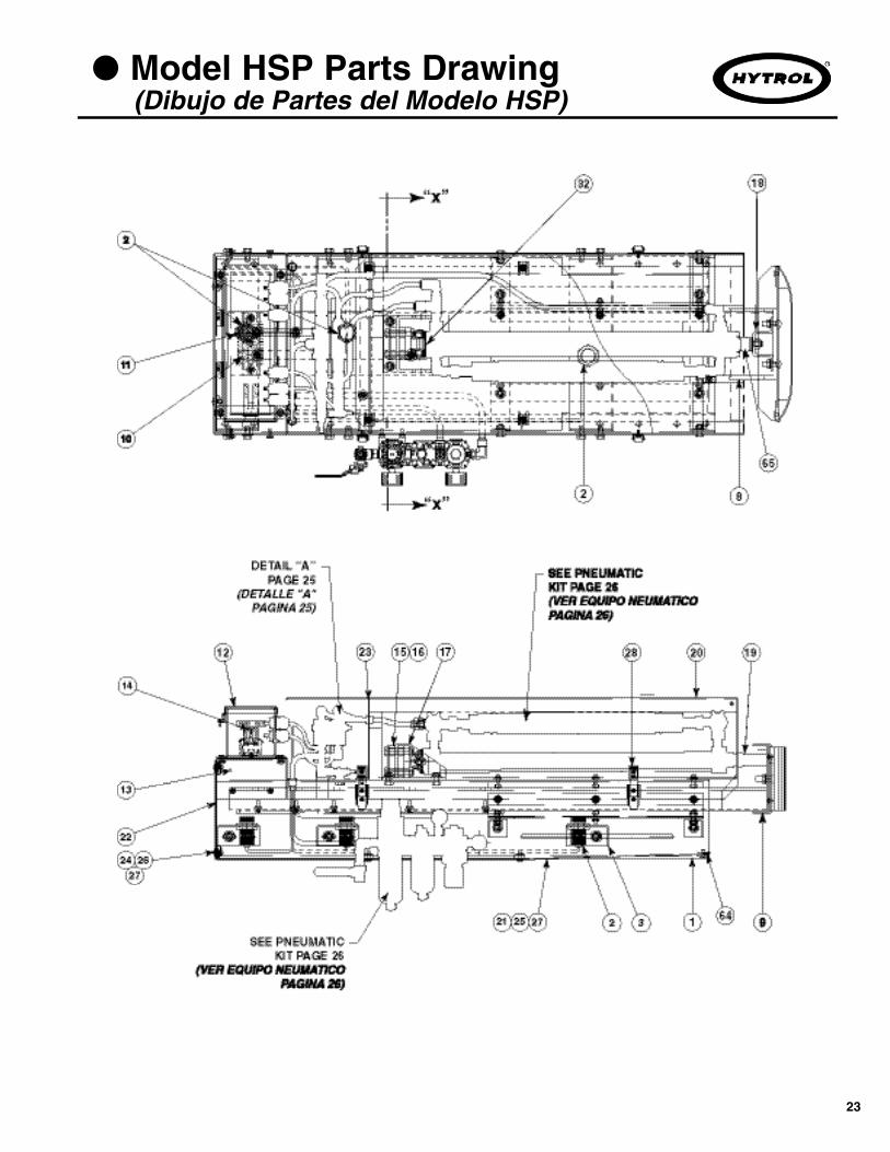
● Model HSP Parts Drawing(Dibujo de Partes del Modelo HSP)
24
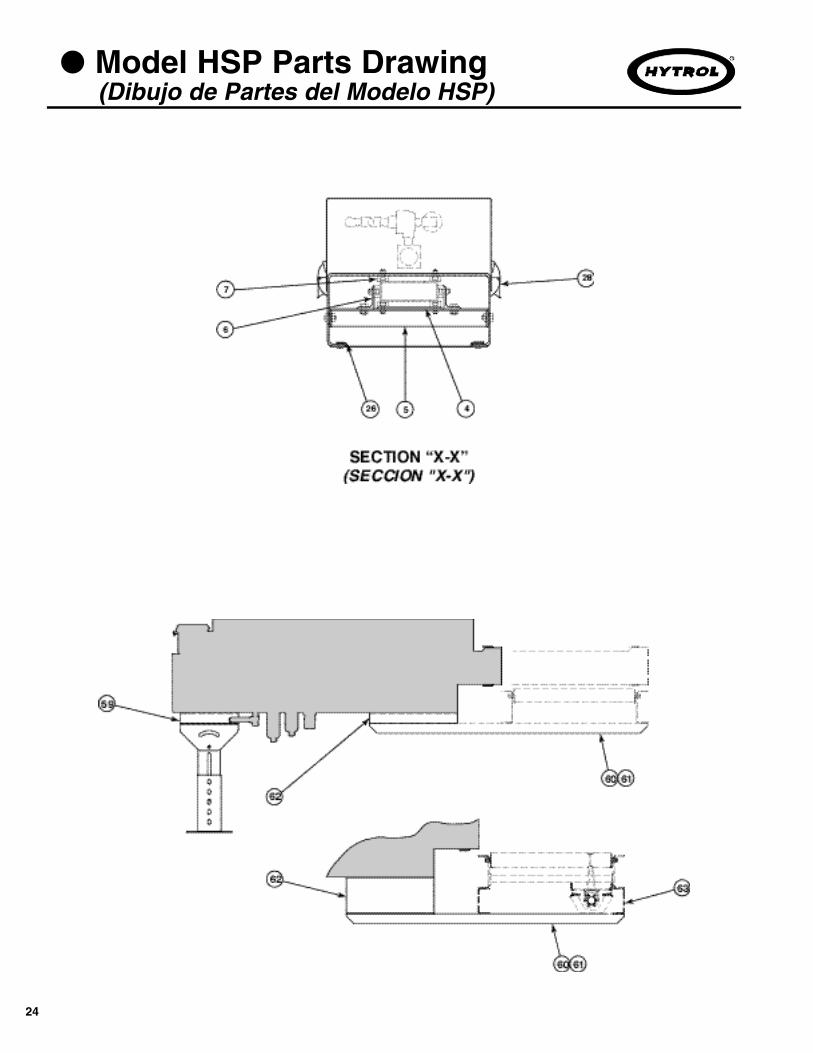
● Model HSP Parts Drawing(Dibujo de Partes del Modelo HSP)
25
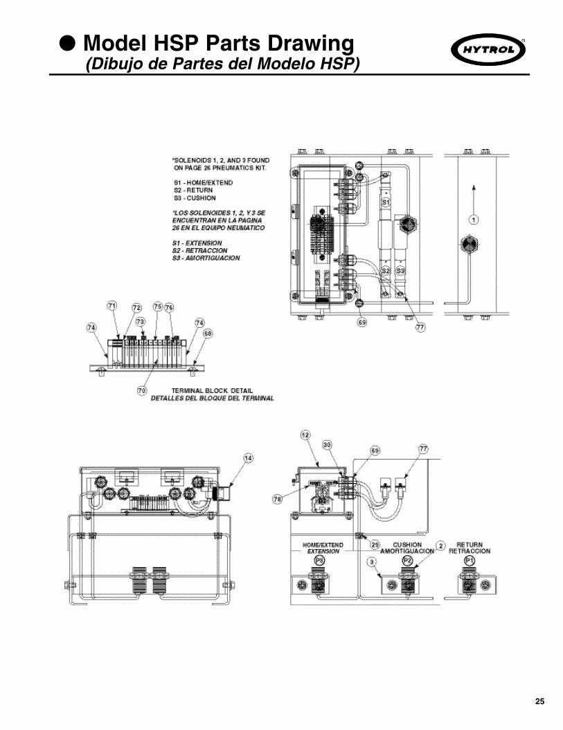
● Model HSP Parts Drawing(Dibujo de Partes del Modelo HSP)
26
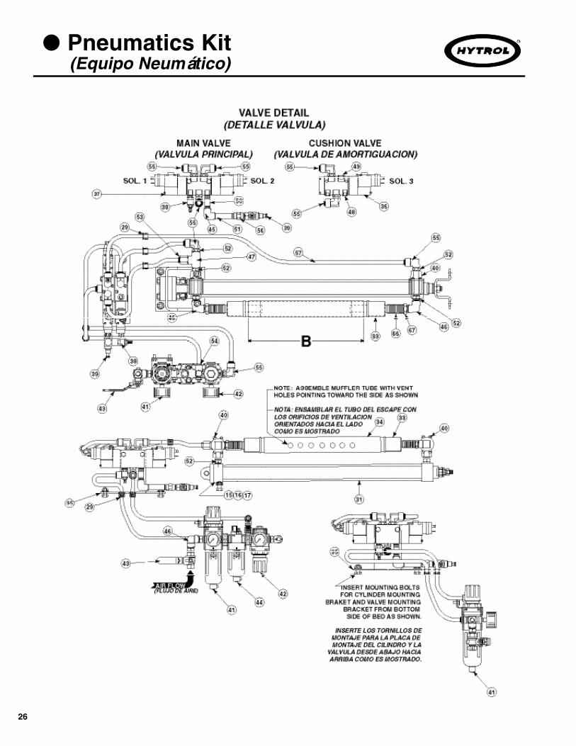
● Pneumatics Kit(Equipo Neumático)

27
Recommended Spare Parts List Highlighted in Gray.(Las Partes de Repuesto Recomendadas se Resaltan en Gris.)
Description Description
● Model HSP Parts List(Lista de Partes del Modelo HSP)
Ref. PartNo. No.46 092.0081 Brass Pipe Elbow–3/8 in. NPT47 092.0261 Brass Pipe Tee–3/8 in. NPT48 092.03715 Brass Pipe Plug–1/4 in. NPT49 092.0372 Steel Pipe Plug–3/8 in. NPT50 092.04911 Brass Pipe Nipple–1/4 in. NPT x 2 in. Long51 092.04931 Brass Pipe Nipple–1/4 in. NPT x 3 in. Long52 092.078 Brass Male Hex Nipple–3/8 in. NPT to 3/8 in. NPT53 094.1403 Brass Male Straight Conn-3/8 in. Plas to 3/8 NPT54 094.1408 Plastic 3/8 in. to 1/4 in. NPT Swivel Elbow55 094.1409 Brass Male Swivel Elbow-3/8 in. Plas to 3/8 NPT56 094.14098 Brass Female Hex Coupling57 094.1149 Polyethylene Tuing 3/8 in. O.D.59 – Support Spacer– B-13940 Model TA– B-13941-1 Model 138-SP & 190-SP– B-13941-2 Model 138-ACC– B-13941-3 Model TL, 190-ACC, 190-ACZ, 190-LR, 190-RB60 – Mounting Angle–LH– B-13791-15L 15 in. OAW Conveyor– B-13791-16L 16 in. OAW Conveyor– B-13791-18L 18 in. OAW Conveyor– B-13791-20L 20 in. OAW Conveyor– B-13791-22L 22 in. OAW Conveyor– B-13791-24L 24 in. OAW Conveyor– B-13791-26L 26 in. OAW Conveyor– B-13791-28L 28 in. OAW Conveyor– B-13791-30L 30 in. OAW Conveyor– B-13791-34L 34 in. OAW Conveyor– B-13791-36L 36 in. OAW Conveyor– B-13791-40L 40 in. OAW Conveyor– B-13791-42L 42 in. OAW Conveyor61 – Mounting Angle–RH– B-13791-15R 15 in. OAW Conveyor– B-13791-16R 16 in. OAW Conveyor– B-13791-18R 18 in. OAW Conveyor– B-13791-20R 20 in. OAW Conveyor– B-13791-22R 22 in. OAW Conveyor– B-13791-24R 24 in. OAW Conveyor– B-13791-26R 26 in. OAW Conveyor– B-13791-28R 28 in. OAW Conveyor– B-13791-30R 30 in. OAW Conveyor– B-13791-34R 34 in. OAW Conveyor– B-13791-36R 36 in. OAW Conveyor– B-13791-40R 40 in. OAW Conveyor– B-13791-42R 42 in. OAW Conveyor62 – Spacer– B-13789 Model TA– B-13790-1 Model 138-SP & 190-SP– B-13790-2 Model 138-ACC– B-13790-3 Model TL, 190-ACC, 190-ACZ, 190-LR, 190-RB63 B-15330 Channel Spacer for Model 138-SP & 190-SP64 B-16076 Guard Mounting Strap65 094.1219 O-Ring AMP # 209 1/8” thick x 11/16” I.D.66 092.05101 1/2” Rigid Conduit Coupling67 092.0781 3/8” Male – 1/2” Male Hex Nipple68 B-19455 Din Rail69 035.1065 Water Tight Strain Relief Bushing70 036.080 Terminal Block71 036.081 Ground Terminal Block72 036.082 Terminal Block End Cover73 036.083 Terminal Block Jumper74 036.084 End Stop75 036.085 Terminal Markers “1–10”76 036.086 Terminal Markers “11–12”77 097.10797 1M Cordset with Rectangular DIN Connector78 099.441 “Test/Reset” Decal
Ref. PartNo. No.1 – Pusher Bed– B-13846 14 in. thru 18 in. Stroke– B-13847 18 in. thru 24 in. Stroke– B-13848 24 in. thru 30 in. Stroke2 032.209 AC/DC Proximity Switch3 B-13786 Switch Mounting Bracket4 B-13782 Guide Attachment Plate5 B-15230 Wearstrip Support Bracket6 B-15232 Side Wearstrip Support Angle7 B-15229 Guide Wearstrip8 – Ram Weldment– B-13794-18 14 in. thru 18 in. Stroke– B-13794-24 18 in. thru 24 in. Stroke– B-13794-30 24 in. thru 30 in. Stroke9 – Ram Face– B-13801-12 12 in. Wide– B-13801-18 18 in. Wide– B-13801-24 24 in. Wide10 B-13777 Sensor Bar–Long11 B-13792 Sensor Bar–Short12 B-13845 Conduit Box13 B-15233 Conduit Box Support14 032-271 3-Position Selector Switch15 B-13775 Cylinder Cushion16 B-13776 Washer Plate17 B-13780 Cylinder Mounting Bracket Assembly–Rear18 B-13793 Cylinder Mounting Bracket19 B-13787 Cylinder Bumper20 – Front Cover– B-13770-18 14 in. thru 18 in. Stroke– B-13770-24 18 in. thru 24 in. Stroke– B-13770-30 24 in. thru 30 in. Stroke21 – Bottom Guard– B-13842-18 14 in. thru 18 in. Stroke– B-13842-24 18 in. thru 24 in. Stroke– B-13842-30 24 in. thru 30 in. Stroke22 B-13841 Back Guard23 B-14382 Back Plate24 043.001 1/4 Turn Stud Fastener #18025 043.004 1/4 Turn Stud Fastener #28026 043.011 1/4 Turn Stud Fastener Receptacle27 043.012 Stud Retainer28 092.165 Over Center Draw Latch with Keeper29 099.1255 Snap Bushing–1/2 in. I.D.30 035.112 Conduit Locknut–1/2 in.31 – Air Cylinder– 094.1215 14 in. thru 18 in. Stroke– 094.1216 18 in. thru 24 in. Stroke– 094.1217 24 in. thru 30 in. Stroke32 094.131 Eye Bracket33 092.162 Muffler34 – Muffler Tube– B-13788-18 14 in. thru 18 in. Stroke– B-13788-24 18 in. thru 24 in. Stroke– B-13788-30 24 in. thru 30 in. Stroke35 B-13783 Valve Bracket36 094.108034 4-Way Single Solenoid Valve37 094.108035 4-Way Double Solenoid Valve38 094.1082 Muffler–1/4 in.NPT39 094.10846 Flow Control Valve–1/4 in. NPT40 094.10858 Quick Exhaust Valve–3/8 in. NPT41 094.192 Filter/Regulator Lubricator with Gauge42 094.196 Cushion Regulator with Gauge43 094.197 Bronze Ball Valve with Vented Exhaust44 094.199 T-Type Spacer 3/8 in. NPT45 092.0071 Brass Pipe Elbow–1/4 in. NPT

HYTROL CONVEYOR COMPANY, INC.2020 Hytrol Drive
Jonesboro, Arkansas 72401
Phone: (870) 935-3700www.hytrol.com
EFFECTIVE FEBRUARY 2005
Printed in the USA 2/05 by Master Printing