Embed Size (px)
Citation preview

Industrivej 3-9 DK-9460 Brovst, Denmark
Tlf.: +45 98 23 60 88 Fax: +45 98 23 61 44
14.10.16
Manual
GRIMAX Belt Grinding Machines
50 – 75 – 100 - 150

2
EU declaration of conformity
hereby declares that
GRIMAX Belt Grinding Machine is manufactured in accordance with the provisions of:
• Directive 2006/42/EC of the European Parliament and of the Council of 17 May 2006 on machinery, and amending Directive 95/16/EC (recast). Short title: Machinery Directive.
Also on accordance with:
• Directive 2014/35/EU of the European Parliament and of the Council of 26 February 2014 on the harmonisation of the laws of the Member States relating to the making available on the market of electrical equipment designed for use within certain voltage limits (recast). Short title: ‘Low Voltage (LVD) Directive’.
• Directive 2014/30/EU of the European Parliament and of the Counciil of 26 February 2014 on the harmonisation of the laws of the Member States relating to electromagnetic compatibility (recast). Short name: ‘Electromagnetic Compatibility (EMC) Directive’.
Industrivej 3-9 DK-9460 Brovst, Danmark Tlf.: 98 23 60 88 Fax: 98 23 61 44
3
Table of Contents
1. TRANSPORT & HANDLING 4
1.1 TRANSPORT 4 1.2 HANDLING 4 1.3 PLACING 4
2. DIRECTIONS 5
2.1 OPERATION 5 2.2 SAFETY RULES FOR STATIONARY POWER TOOLS. 5 2.3 MAINTENANCE 7
3. SPARE PARTS LIST 8
3.1 DRAWING OF BELT GRINDING MACHINE WITHOUT EXHAUST SYSTEM 8 3.2 SPARE PARTS LIST FOR BELT GRINDING MACHINE WITHOUT EXHAUST SYSTEM 9 3.3 DRAWING FOR BELT GRINDING MACHINE WITH EXHAUST SYSTEM 10 3.4 SPARE PARTS LIST FOR BELT GRINDING MACHINE WITH EXHAUST SYSTEM 11
4. TECHNICAL DATA 13
4.1 TECHNICAL SPECIFICATIONS 13 4.2 DIMENSIONS 13 4.3 CIRCUIT DIAGRAMS 14 4.4 PRESSUREDIAGRAM 20
5. WARRANTY 21
5.1 GUARANTEE 21
4
1. Transport & Handling
1.1 Transport
The GRIMAX belt grinding machine is packed in protective wrapping and delivered on a pallet with the following measures: 120 x 80 x 120 cm
1.2 Handling
The machine can easily be transported on the pallet on which it is delivered.
1.3 Placing
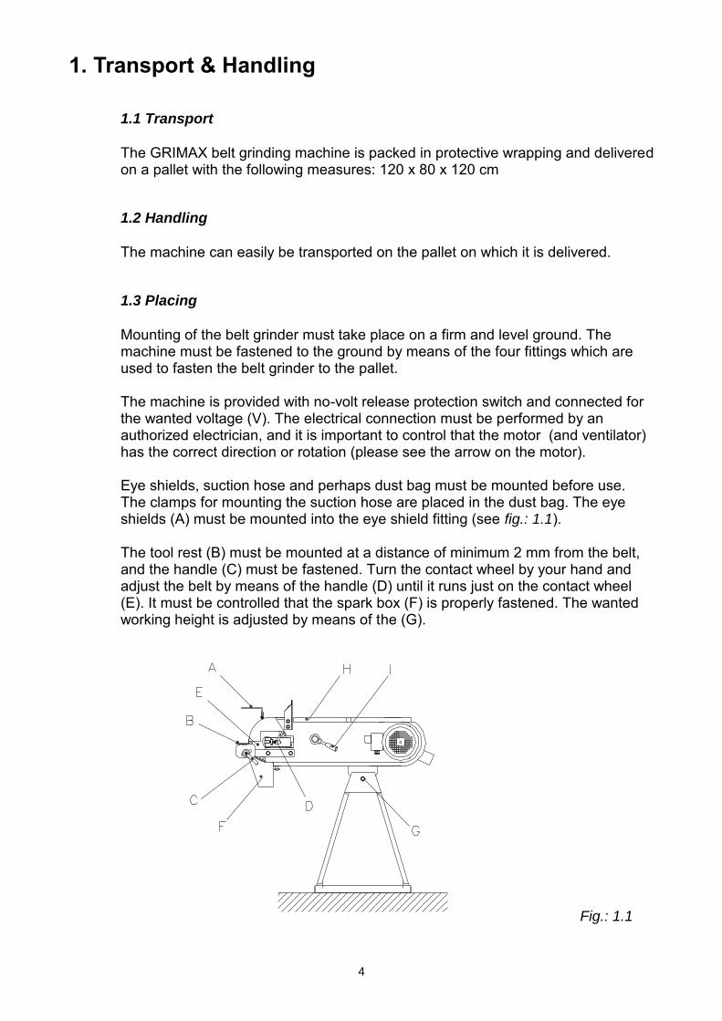
Mounting of the belt grinder must take place on a firm and level ground. The machine must be fastened to the ground by means of the four fittings which are used to fasten the belt grinder to the pallet. The machine is provided with no-volt release protection switch and connected for the wanted voltage (V). The electrical connection must be performed by an authorized electrician, and it is important to control that the motor (and ventilator) has the correct direction or rotation (please see the arrow on the motor). Eye shields, suction hose and perhaps dust bag must be mounted before use. The clamps for mounting the suction hose are placed in the dust bag. The eye shields (A) must be mounted into the eye shield fitting (see fig.: 1.1). The tool rest (B) must be mounted at a distance of minimum 2 mm from the belt, and the handle (C) must be fastened. Turn the contact wheel by your hand and adjust the belt by means of the handle (D) until it runs just on the contact wheel (E). It must be controlled that the spark box (F) is properly fastened. The wanted working height is adjusted by means of the (G).
Fig.: 1.1
5
2. Directions
2.1 Operation
After adjustment and connection the belt grinding machine is ready for use. The grinding can take place by the contact wheel (E) or on the surface grinding table by opening the cover (H). The lifetime of a new belt is prolonged if the grinding starts with a light pressure.
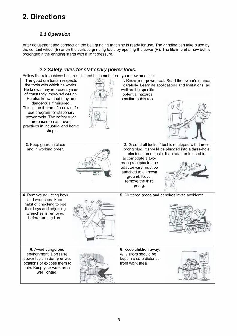
2.2 Safety rules for stationary power tools.
Follow them to achieve best results and full benefit from your new machine. The good craftsman respects the tools with which he works. He knows they represent years of constantly improved design.
He also knows that they are dangerous if misused.
This is the theme of a new safe-use program for stationary
power tools. The safety rules are based on approved
practices in industrial and home shops
1. Know your power tool. Read the owner’s manual carefully. Learn its applications and limitations, as
well as the specific potential hazards
peculiar to this tool.
2. Keep guard in place and in working order.
3. Ground all tools. If tool is equipped with three-prong plug, it should be plugged into a three-hole
electrical receptacle. If an adapter is used to accomodate a two-
prong receptacle, the adapter wire must be attached to a known
ground. Never remove the third
prong.
4. Remove adjusting keys and wrenches. Form
habit of checking to see that keys and adjusting wrenches is removed before turning it on.
5. Cluttered areas and benches invite accidents.
6. Avoid dangerous environment. Don’t use
power tools in damp or wet locations or expose them to rain. Keep your work area
well lighted.
6. Keep children away. All visitors should be kept in a safe distance from work area.

6
8. Make workshop kidproof with padlocks, master switches, or by removing starter keys.
9. Don’t force tool. It will do the job better and be safer at the rate for which it was designed.
.
10. Use right tool. Don’t force tool or attachment to do a job it was not designed for.
11. Wear proper apparel. Wear no loose clothing, gloves, neckties, rings,
bracelets, or other jewelry which may get
caught in moving parts. Non-slip footwear is
recommended. Wear protective hair covering
to contain long hair.
12. Always use safety glasses. Also use face or dust mask if cutting operation is dusty. Everyday eyeglasses only have impact resistant lenses. They are NOT safety glasses.
13. Secure works. Use clamps or vise to hold works, when pratical. It’s safer than using your hands and it frees both hands to operate tool.
14. Don’t overreach.
Keep proper footing and balance at all times.
15. Maintain tools with care. Keep tools sharp and clean for best and safest performance. Follow instructions for lubricating and changing accessories.
16. Disconnect tools before servicing and when changing accessories such as grinding wheels, polishing mops, grinding belts, blades, bits, cutters, etc.
17. Reduce the risk of unintentional starting. Make sure switch is in off position before plugging in.
18. Use recommended accessories. Consult owner’s manual for recommended accessories. Use of improper accessories may cause risk of injury to persons.
7
2.3 Maintenance
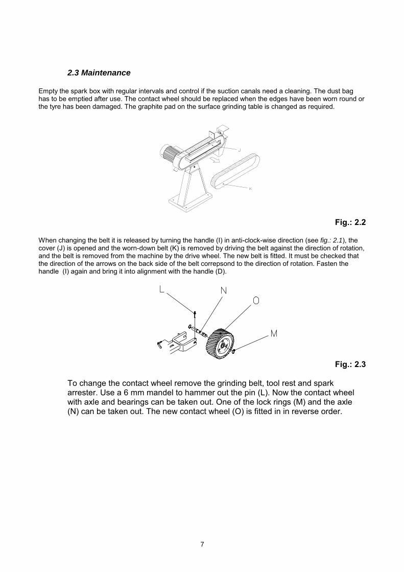
Empty the spark box with regular intervals and control if the suction canals need a cleaning. The dust bag has to be emptied after use. The contact wheel should be replaced when the edges have been worn round or the tyre has been damaged. The graphite pad on the surface grinding table is changed as required.
Fig.: 2.2
When changing the belt it is released by turning the handle (I) in anti-clock-wise direction (see fig.: 2.1), the cover (J) is opened and the worn-down belt (K) is removed by driving the belt against the direction of rotation, and the belt is removed from the machine by the drive wheel. The new belt is fitted. It must be checked that the direction of the arrows on the back side of the belt correpsond to the direction of rotation. Fasten the handle (I) again and bring it into alignment with the handle (D).
Fig.: 2.3
To change the contact wheel remove the grinding belt, tool rest and spark arrester. Use a 6 mm mandel to hammer out the pin (L). Now the contact wheel with axle and bearings can be taken out. One of the lock rings (M) and the axle (N) can be taken out. The new contact wheel (O) is fitted in in reverse order.
8
3. Spare Parts List
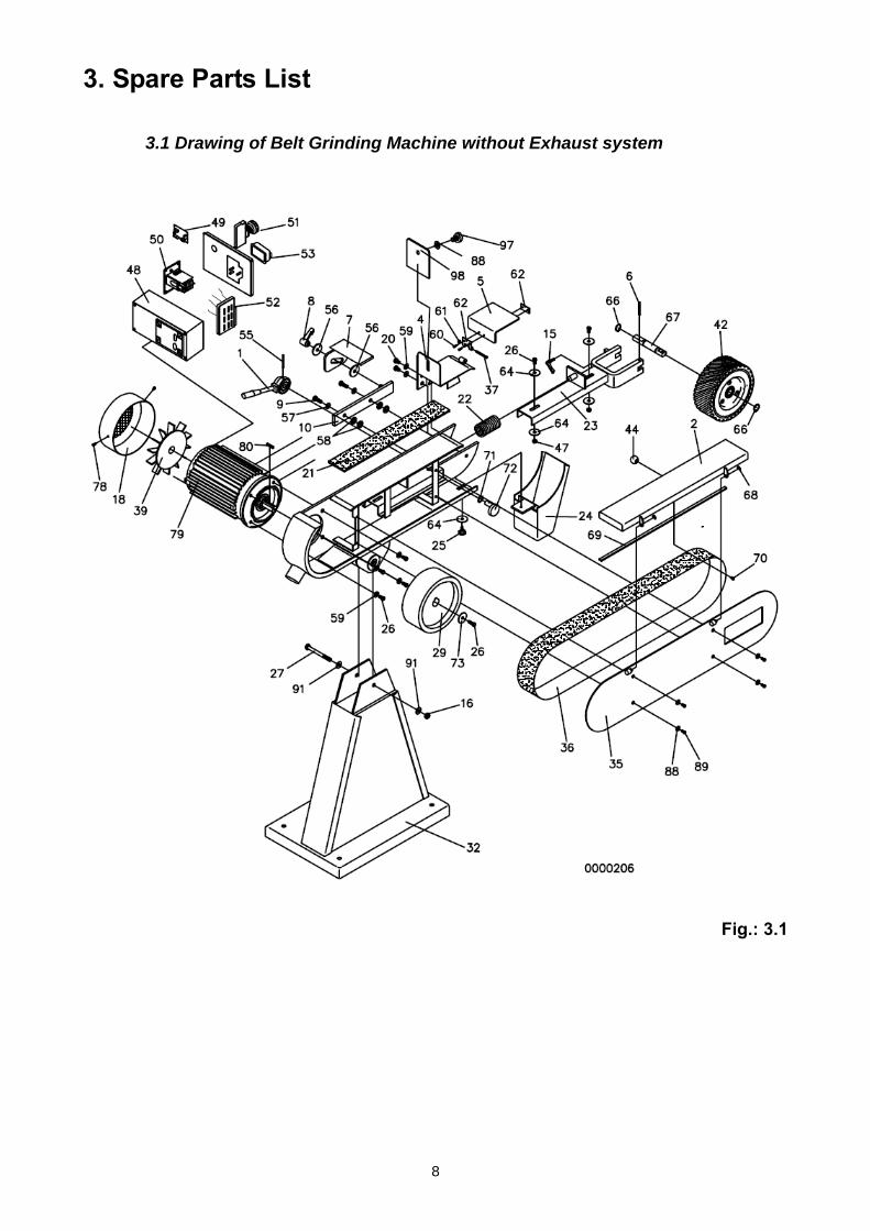
3.1 Drawing of Belt Grinding Machine without Exhaust system
Fig.: 3.1
9
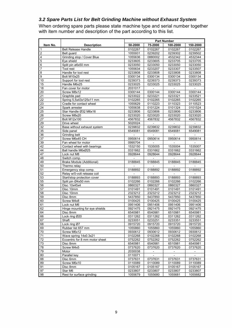
3.2 Spare Parts List for Belt Grinding Machine without Exhaust System
When ordering spare parts please state machine type and serial number together with item number and description of the part according to this list.
Part Number
Item No. Description 50-2000 75-2000 100-2000 150-2000 1 Belt Release Handle 0102267 0102267 0102267 0102267 2 Belt guard 1055931 0239202 0239302 0239502 4 Grinding stop / Cover Blue 1055636 0880002 4532342 4532344 5 Eye shield 0233605 0233605 0233705 0233705 6 Split pin ø6x50 mm 0233050 0233050 0233050 0233050 7 Tool rest 1055634 0233207 0233307 0233507 8 Handle for tool rest 0233808 0233808 0233808 0233808 9 Bolt M10x25 0300134 0300134 0300134 0300134 10 Support for tool rest 0239373 0239373 0239373 0239373 15 Handle M6x25 0233025 0233025 0233025 0233025 18 Fan cover for motor 2031017 - - - 20 Screw M8x12 0300144 0300144 0300144 0300144 21 Graphite pad 0233022 0233221 0233321 0233521 22 Spring 5,5x43x125x11 mm 0102265 0102265 0102265 0102265 23 Cradle for contact wheel 1055629 0110223 0110323 0110523 24 Spark arrester 1055638 0101224 0101324 0101524 25 Star Handle Ø32 M6x16 0233806 0233806 0233806 0233806 26 Screw M8x20 0233020 0233020 0233020 0233020 27 Bolt M12x100 4567832 4567832 4567832 4567832 29 Drive wheel 5020024 - - - 32 Base without exhaust system 0239832 0239832 0239832 0239832 35 Side panel 6549081 6549081 6549081 6549081 36 Grinding belt - - - - 37 Screw M6x45 CH 0950614 0950614 0950614 0950614 39 Fan wheel for motor 0995704 - - - 42 Contact wheel with bearings 1532150 1535005 1535004 1535007 44 Ball handle M6xØ25 0331662 0331662 0331662 0331662 47 Lock nut M8 0928644 0928644 0928644 0928644 48 Switch comp. - - - - 49 Brake Module (Additional) 0188845 0188845 0188845 0188845 50 Thermo relay - - - - 51 Emergency stop comp. 0188892 0188892 0188892 0188892 52 Relay w/0-volt retease coil - - - - 53 Start/stop protection cover 0188893 0188893 0188893 0188893 55 Split pin Ø4x50 mm 0102266 0102266 0102266 0102266 56 Disc 10x45x4 0860327 0860327 0860327 0860327 57 Disc 10mm 0101491 0101491 0101491 0101491 58 Disc 10mm 2323212 2323212 2323212 2323212 59 Disc 8mm 5437850 5437850 5437850 5437850 60 Screw M4x8 0100425 0100425 0100425 0100425 61 Lock nut M6 0951406 0951406 0951406 0951406 62 Hinge mounting for eye shields 0921475 0921475 0921475 0921475 64 Disc 8mm 6540981 6540981 6510981 6540981 66 Lock ring Ø20 0311262 0311262 0311262 0311262 67 Shaft 0233051 0233251 0233351 0233551 68 Lock ring Ø7 0915720 0915720 0915720 0915720 69 Rubber list 657 mm 1055860 1055860 1055860 1055860 70 Screw M6x12 0930612 0930612 0930612 0930612 71 Wave spring 14x0.3x21 0102268 0102268 0102268 0102268 72 Eccentric for 8 mm motor sheet 0752262 0752262 0752262 0752262 73 Disc 8mm 6540981 6540981 6510981 6540981 78 Screw M4x5 0737620 0737620 0737620 0737620 79 Motor 2030038 - - - 80 Parallel key 0110071 - - - 88 Disc 6mm 0737631 0737631 0737631 0737631 89 Screw M6x10 0110089 0110089 0110089 0110089 91 Disc 8mm 0105167 0105167 0105167 0105167 97 Star M6 0233807 0233807 0233807 0233807 98 Rest for surface grinding 1055679 1055680 1055681 1055682
10
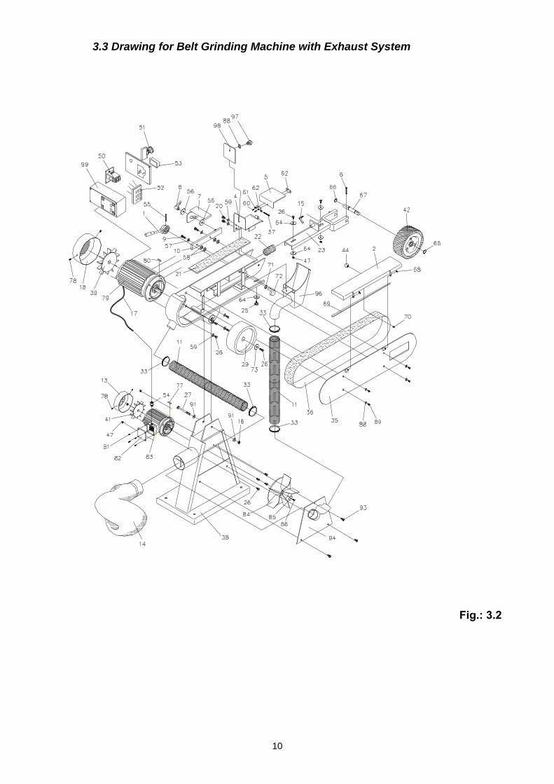
3.3 Drawing for Belt Grinding Machine with Exhaust System
Fig.: 3.2
11
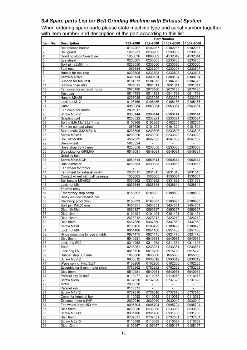
3.4 Spare parts List for Belt Grinding Machine with Exhaust System
When ordering spare parts please state machine type and serial number together with item number and description of the part according to this list. Part Number Item No. Description 75X-2000 75X-2000 100X-2000 150X-2000 1 Belt release handle 0102267 0102267 0102267 0102267 2 Belt guard 1055931 0239202 0239302 0239502 4 Grinding stop/Cover Blue 1055636 0880002 4532342 4532344 5 Eye shield 0233605 0233605 0233705 0233705 6 Split pin ø6x50 mm 0233050 0233050 0233050 0233050 7 Tool rest 1055634 0233207 0233307 0233507 8 Handle for tool rest 0233808 0233808 0233808 0233808 9 Screw M10x25 0300134 0300134 0300134 0300134 10 Support for tool rest 0104373 0104373 0104373 0104373 11 Suction hose ø63 7891011 7891011 7891011 7891011 13 Fan cover for exhaust motor 2075180 2075180 2075180 2075180 14 Dust bag 0811793 0811793 0811793 0811793 15 Handle M6x25 0233025 0233025 0233025 0233025 16 Lock nut M12 0105166 0105166 0105166 0105166 17 Cable 0963084 0963084 0963084 0963084 18 Fan cover for motor 2031017 - - - 20 Screw M8x12 0300144 0300144 0300144 0300144 21 Graphite pad 0233022 0233221 0233321 0233521 22 Spring 5,5x43x125x11 mm 0102265 0102265 0102265 0102265 23 Fork for contact wheel 1055629 0101224 0101324 0101524 25 Star handle Ø32 M6x16 0233806 0233806 0233806 0233806 26 Screw M8x20 0233020 0233020 0233020 0233020 27 Bolt M12x100 4567832 4567832 4567832 4567832 29 Drive wheel 5020024 - - - 33 Hose strap 58-75 mm 0233058 0233058 0233058 0233058 35 Side plate for GRIMAX 6549081 6549081 6549081 6549081 36 Grinding belt - - - - 37 Screw M6x45 CH 0950614 0950614 0950614 0950614 38 Dust extractor 0239853 0239853 0239853 0239853 39 Fan wheel for motor - - - - 41 Fan wheel for exhaust motor 2031015 2031015 2031015 2031015 42 Contact wheel with ball bearings 1535005 1535005 1535004 1535007 44 Ball handle M6xØ25 0331662 0331662 0331662 0331662 47 Lock nut M8 0928644 0928644 0928644 0928644 50 Thermo relay - - - - 51 Emergency stop comp. 0188892 0188892 0188892 0188892 52 Relay w/0-volt retease coil - - - - 53 Start/stop protection 0188893 0188893 0188893 0188893 55 Split pin Ø4x50 mm 3454351 3454351 3454351 3454351 56 Disc 10x45x4 0860327 0860327 0860327 0860327 57 Disc 10mm 0101491 0101491 0101491 0101491 58 Disc 10mm 2323212 2323212 2323212 2323212 59 Disc 8mm 5437850 5437850 5437850 5437850 60 Screw M4x8 0100425 0100425 0100425 0100425 61 Lock nut M6 0951406 0951406 0951406 0951406 62 Hinge mounting for eye shields 0921475 0921475 0921475 0921475 64 Disc 8mm 6540981 6540981 6540981 6540981 66 Lock ring Ø20 0311262 0311262 0311262 0311262 67 Shaft 0233051 0233251 0233351 0233551 68 Lock ring Ø7 0915720 0915720 0915720 0915720 69 Rubber strip 657 mm 1055860 1055860 1055860 1055860 70 Screw M6x12 0930612 0930612 0930612 0930612 71 Wave spring 14x0.3x21 0102268 0102268 0102268 0102268 72 Eccentric for 8 mm motor sheet 0752262 0752262 0752262 0752262 73 Disc 8mm 6540981 6540981 6540981 6540981 77 Parallel key 36x6x6 0110077 0110077 0110077 0110077 78 Screw M4x5 0737620 0737620 0737620 0737620 79 Motor 2030038 - - - 80 Parallel key 0110071 - - - 81 Screw M4x12 0737610 0737610 0737610 0737610 82 Cover for terminal box 0110082 0110082 0110082 0110082 83 Exhaust motor 0.5HP 2030040 2030040 2030040 2030040 84 Fan wheel large 250 mm 0995704 0995704 0995704 0995704 85 Disc 5mm 0233030 0233030 0233030 0233030 86 Screw M5x30 0331786 0331786 0331786 0331786 88 Disc 6mm 0737631 0737631 0737631 0737631 89 Screw M6x10 0110089 0110089 0110089 0110089 91 Disc 12mm 0105167 0105167 0105167 0105167

12
93 Screw Taptite M6x16 0910616 0910616 0910616 0910616 94 Side plate for base 0239128 0239128 0239128 0239128 96 Spark box with exhaust system 1055643 0239252 0239352 0239552 97 Star M6 0233807 0233807 0233807 0233807 98 Rest for surface grinding 1055679 1055680 1055681 1055682 99 Switch comp. - - - -
13
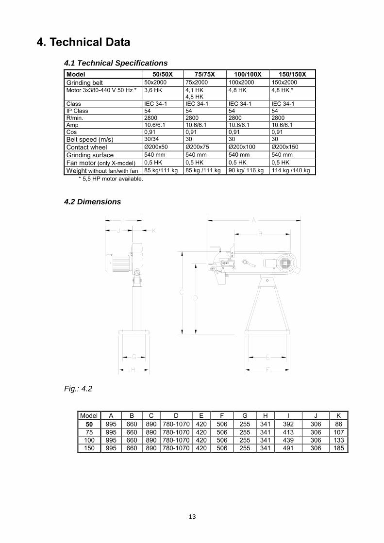
4. Technical Data 4.1 Technical Specifications
Model 50/50X 75/75X 100/100X 150/150X Grinding belt 50x2000 75x2000 100x2000 150x2000 Motor 3x380-440 V 50 Hz * 3,6 HK 4,1 HK
4,8 HK 4,8 HK 4,8 HK *
Class IEC 34-1 IEC 34-1 IEC 34-1 IEC 34-1 IP Class 54 54 54 54 R/min. 2800 2800 2800 2800 Amp 10.6/6.1 10.6/6.1 10.6/6.1 10.6/6.1 Cos 0,91 0,91 0,91 0,91 Belt speed (m/s) 30/34 30 30 30 Contact wheel Ø200x50 Ø200x75 Ø200x100 Ø200x150 Grinding surface 540 mm 540 mm 540 mm 540 mm Fan motor (only X-model) 0,5 HK 0,5 HK 0,5 HK 0,5 HK Weight without fan/with fan 85 kg/111 kg 85 kg /111 kg 90 kg/ 116 kg 114 kg /140 kg
* 5,5 HP motor available.
4.2 Dimensions
Fig.: 4.2
Model A B C D E F G H I J K 50 995 660 890 780-1070 420 506 255 341 392 306 86 75 995 660 890 780-1070 420 506 255 341 413 306 107 100 995 660 890 780-1070 420 506 255 341 439 306 133 150 995 660 890 780-1070 420 506 255 341 491 306 185
14
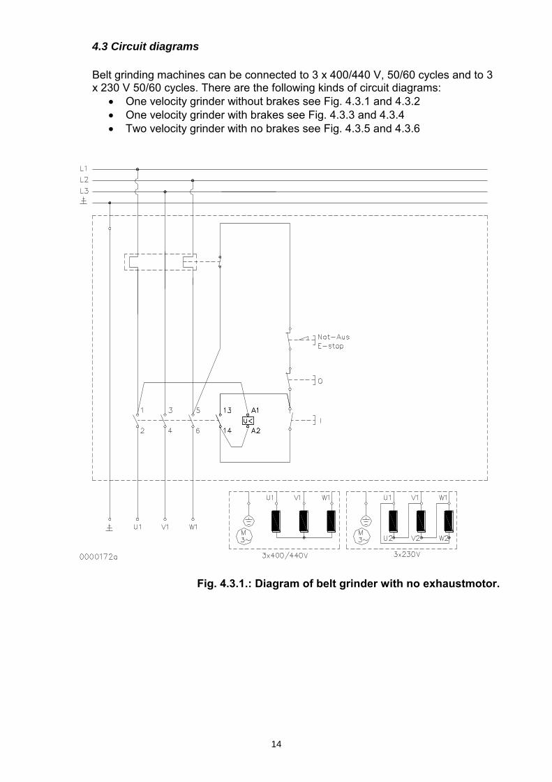
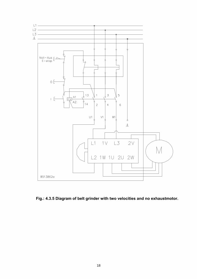
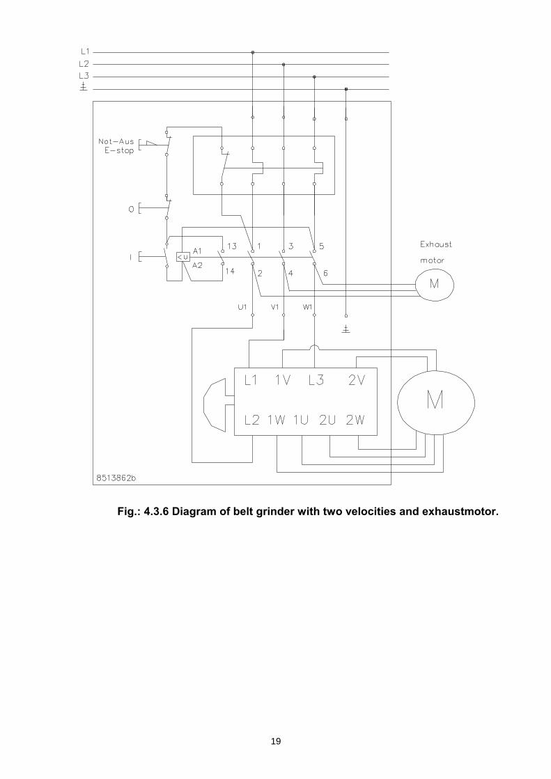
4.3 Circuit diagrams
Belt grinding machines can be connected to 3 x 400/440 V, 50/60 cycles and to 3 x 230 V 50/60 cycles. There are the following kinds of circuit diagrams:
• One velocity grinder without brakes see Fig. 4.3.1 and 4.3.2 • One velocity grinder with brakes see Fig. 4.3.3 and 4.3.4 • Two velocity grinder with no brakes see Fig. 4.3.5 and 4.3.6
Fig. 4.3.1.: Diagram of belt grinder with no exhaustmotor.
15
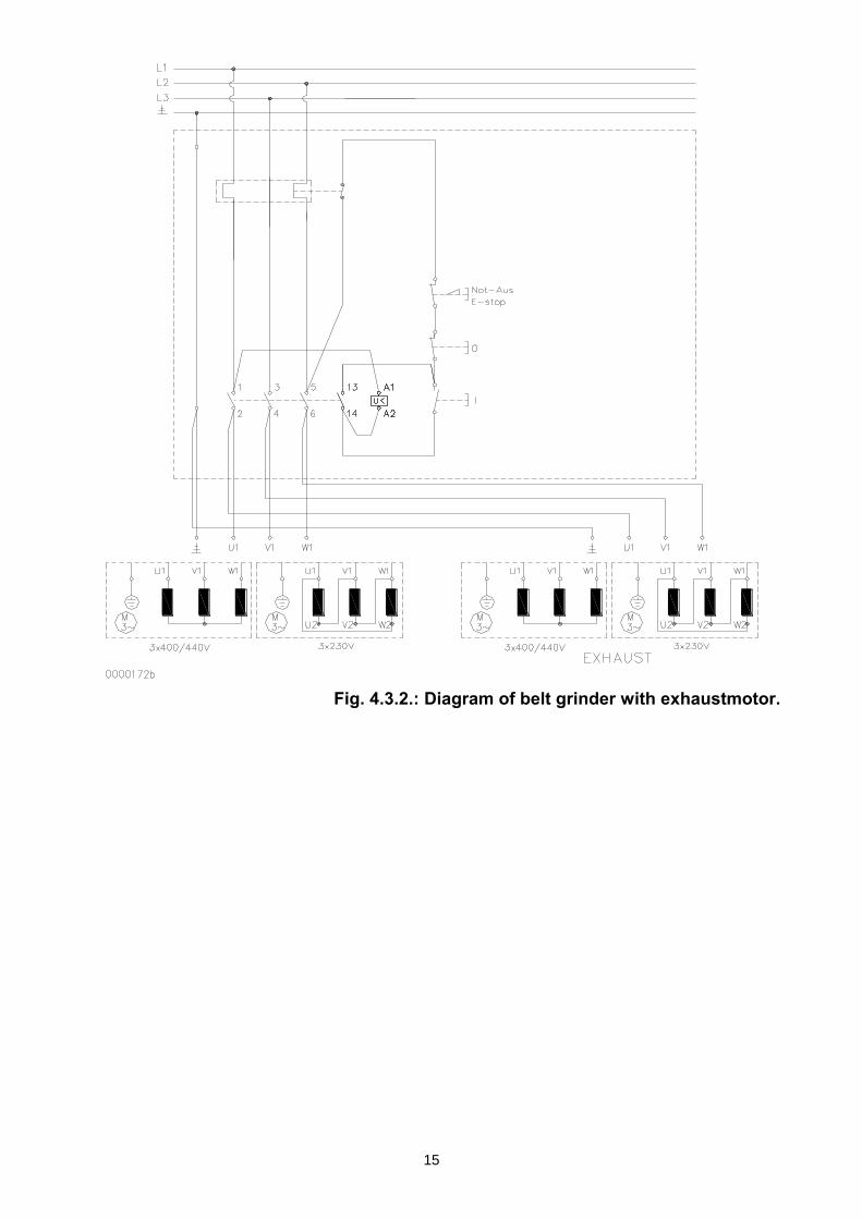
Fig. 4.3.2.: Diagram of belt grinder with exhaustmotor.
16
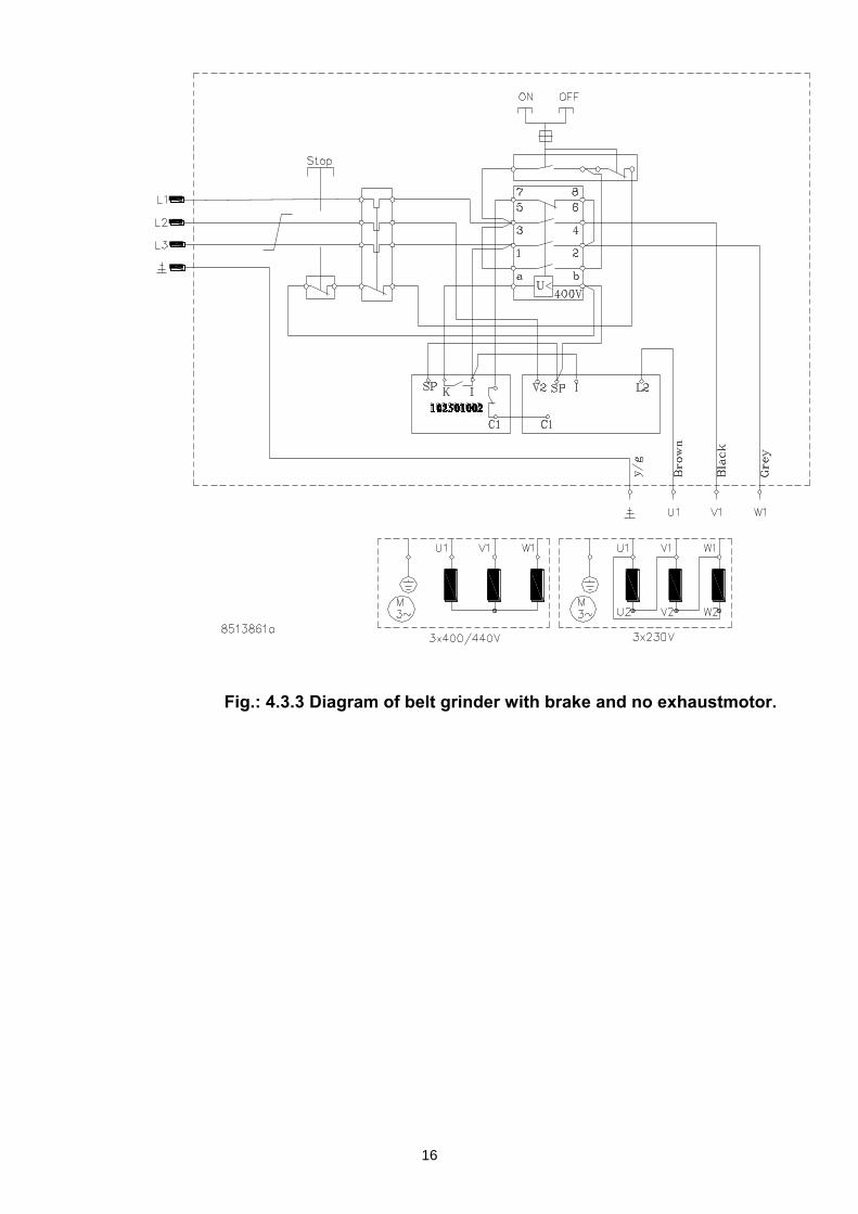
Fig.: 4.3.3 Diagram of belt grinder with brake and no exhaustmotor.
17
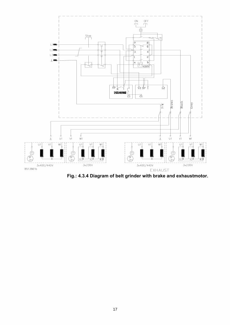
Fig.: 4.3.4 Diagram of belt grinder with brake and exhaustmotor.
18
Fig.: 4.3.5 Diagram of belt grinder with two velocities and no exhaustmotor.
19
Fig.: 4.3.6 Diagram of belt grinder with two velocities and exhaustmotor.
20
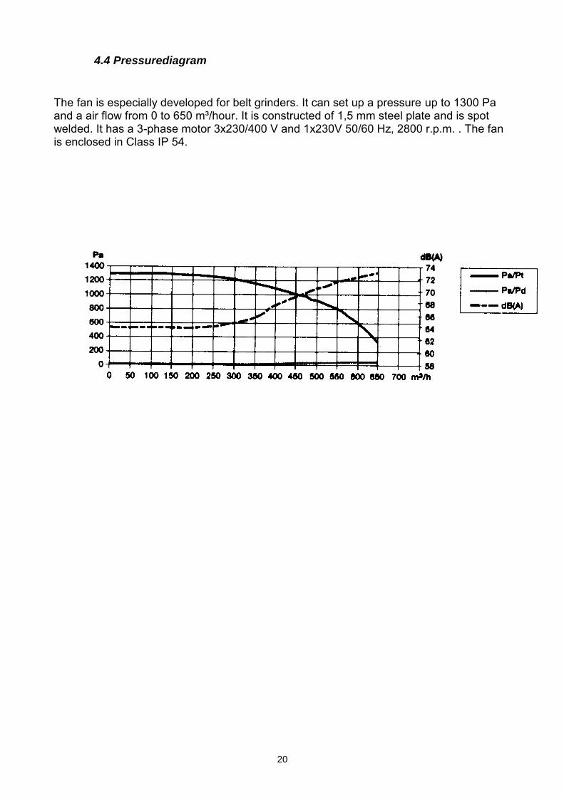
4.4 Pressurediagram
The fan is especially developed for belt grinders. It can set up a pressure up to 1300 Pa and a air flow from 0 to 650 m³/hour. It is constructed of 1,5 mm steel plate and is spot welded. It has a 3-phase motor 3x230/400 V and 1x230V 50/60 Hz, 2800 r.p.m. . The fan is enclosed in Class IP 54.

LIMITED WARRANTY
Industrial Tool & Machinery Sales (hereinafter refered to as ITMS) will, within twelve (12) months from the original date of purchase, repair or replace any goods found to be defective in materials or workmanship.This warranty is void if the item has been damaged by accident, neglect, improper service or other causes not arising out of defects in materials or workmanship. This warranty does not apply to machines and/or components which have been altered, changed, or modified in any way, or subjected to overloading or use beyond recommended capacities and specifications. Worn componentry due to normal wear and tear is not a warranty claim. Goods returned defective shall be returned prepaid freight to ITMS or agreed repair agent, which shall be the buyer’s sole and exclusive remedy for defective goods. ITMS accepts no additional liability pursuant to this guarantee for the costs of travelling or transportation of the product or parts to and from ITMS or the service agent or dealer, such costs are not included in this warranty.
Our goods come with guarantees which cannot be excluded under the Australian Consumer Law. You are entitled to replacement or refund for a major failure and to compensation for other reasonably foreseeable loss or damage. You are also entitled to have the goods repaired or replaced if the goods fail to be of acceptable quality and the failure does not amount to a major failure.
THE MANUFACTURER RESERVES THE RIGHT TO MAKE IMPROVEMENTS AND MODIFICATIONS TO DESIGN WITHOUT PRIOR NOTICE.
PRODUCTS IMPORTED AND DISTRIBUTED NATIONALLY BY:
INDUSTRIAL TOOL & MACHINERY SALES18 BUSINESS ST, YATALA QLD 4207T: 07 3287 1114 E: [email protected]: 07 3287 1115 W: www.industrialtool.com.au