Embed Size (px)
Citation preview

Ingeniería e Investigación
ISSN: 0120-5609
Universidad Nacional de Colombia
Colombia
Centeno González, Luz María; Castillo Castañeda, Eduardo; Becerra Santiago, Luis Omar; Rochín
García, Alberto
A magnetic suspension system for measuring liquid density
Ingeniería e Investigación, vol. 33, núm. 1, enero-abril, 2013, pp. 46-51
Universidad Nacional de Colombia
Bogotá, Colombia
Available in: http://www.redalyc.org/articulo.oa?id=64328174009
How to cite
Complete issue
More information about this article
Journal's homepage in redalyc.org
Scientific Information System
Network of Scientific Journals from Latin America, the Caribbean, Spain and Portugal
Non-profit academic project, developed under the open access initiative
INGENIERÍA E INVESTIGACIÓN VOL. 33 No. 1, APRIL 2013 (46-51)
46
A magnetic suspension system for measuring
liquid density
Desarrollo de un sistema de suspensión magnética para la determinación
de densidad de líquidos
L. M. Centeno1, E. Castillo2, L. O. Becerra3, A. Rochin4
ABSTRACT
Density is a derived quantity of mass and length; it is defined as mass per volume unit and its SI unit is kg/m3. National metrology insti-
tutes have been designing and building their own magnetic suspension systems during the last 5 decades for making fluid density
measurements; this has allowed them to carry out research into liquids and gases’ physical characteristics. This paper was aimed at
designing and developing a magnetic suspension system for a magnetic balance used in determining liquid density to be used in
CENAM’s metrology density laboratories.
Keywords: Hydrostatic weighing, density, magnetic suspension.
RESUMEN
La densidad es una magnitud derivada de las magnitudes de base masa y longitud, está definida como masa por unidad de vo-
lumen y su unidad en el Sistema Internacional de Unidades (SI) es el kg/m3. En las últimas cinco décadas, en el ámbito de la metro-
logía primaria, se han desarrollado sistemas de suspensión magnética para la determinación de densidad de fluidos, lo que ha
permitido realizar investigaciones sobre las características físicas de líquidos y gases. El presente trabajo tiene como objetivo el desa-
rrollo y diseño de un sistema de suspensión magnética que será utilizado en una balanza de suspensión magnética para determinar
la densidad de líquidos en los laboratorios de metrología de densidad, en el Centro Nacional de Metrología (Cenam).
Palabras clave: densidad, suspensión magnética, fuerza magnética.
Received: May 23th 2011
Accepted: January 10th 2013
Introduction1 2
The magnetic suspension system has been studied and developed
by authors such as Hurley, Ziehlmann and Mizuno. The common
factor in their works is that they have followed a basic type of
system consisting of an electromagnet, a ferromagnetic body, a
position detection system and a closed loop control, as shown in
Figure 1 (Hurley, 1997; Ziehlmann, 2000).
A variant of the previous system may be obtained by placing a
permanent magnet which interacts with the electromagnet; the
force needed by the electromagnet to levitate an object thus
becomes reduced, not necessarily being a ferromagnetic one
[Kleinrahm, 1986]. This variant minimises electromagnet power
1 Luz María Centeno González. M.Sc. Tecnología Avanzada, CICATA, Instituto
Politécnico Nacional. Affiliation: Centro Nacional de Metrología, México. México. E-
mail: [email protected]. 2 Dr. Eduardo Castillo Castañeda. Dr. in Automatic Control, Institut National
Polytechnique de Grenoble. France. Affiliation: CICATA, Instituto Politécnico
Nacional, México. E-mail: [email protected]. 3 Luis Omar Becerra Santiago. M.Sc. Diseño Mecánico, Instituto Tecnológico de
Celaya, Gto. México. Affiliation: Centro Nacional de Metrología, México. E-mail:
[email protected]. 4 Alberto Rochín García. M. en C. en Electrónica, INAOE. Puebla. México. Affilia-
tion: Facultad de Filosofía, UNAM, México. E-mail: [email protected].
How to cite: Centeno, L. M., Castillo, E., Becerra, L. O., Rochin, A., A Magnetic
Suspension System for Measuring Liquid Density., Ingeniería e Investigación Journal,
Vol. 33, No.1, Apr., 2013, pp. 46-51.
consumption, which is reflected in the heat so generated and,
thereby, in low variation of its current. The latter system config-
uration is widely used in the field of density metrology.
Figure 1. Basic magnetic suspension system
There are many ways of using the magnetic levitation in different
kinds of measurement systems; another configuration proposed
for density metrology has two permanent magnets and capillary
tubes, and sample density is obtained as a function of a levitated
object’s height (Mirica K. A., 2009).
This paper presents a design for and stability analysis of a mag-
netic levitation system; it will become part of a complete meas-
urement system for measuring liquid density. Stability regarding
mass measurement is thus very important, varying by no more
than 1 mg, since the standard deviation of measurements repre-
CENTENO, CASTILLO, BECERRA AND ROCHIN
INGENIERÍA E INVESTIGACIÓN VOL. 33 No. 1, APRIL 2013 (46-51) 47
sents the second largest contribution to liquid density uncertain-
ty budget (Becerra L, 1998), i.e. on the proposed system, deter-
mined by the levitated object’s position stability.
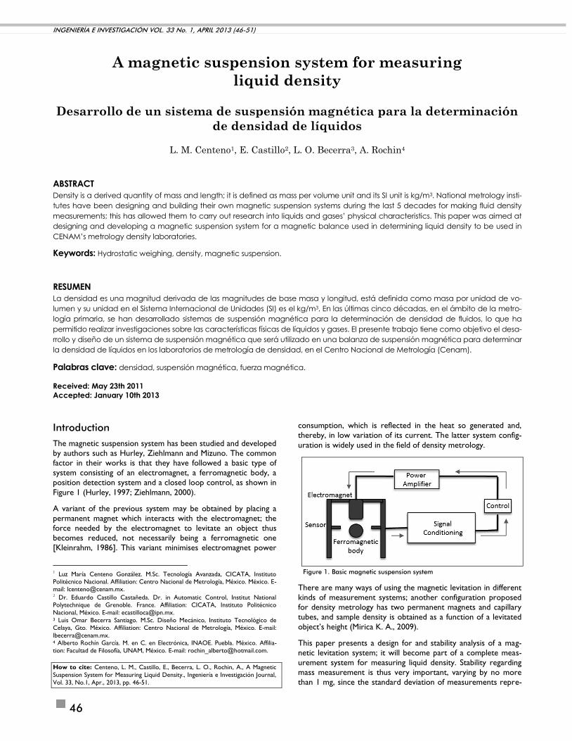
Magnetic suspension systems in determining liquid density
The reference object (solid density standard) in a hydrostatic
weighing system is connected to the balance by a wire (through a thread passing over the surface of the liquid to be measured).
The reference object’s apparent weight loss indicates displaced
liquid mass (liquid buoyancy). The force acting on the balance is a
measure of the mass of the reference object. If the connecting
wire were removed, then the reference object would float or
sink freely in the liquid, depending on its density. If a magnetic
field were generated to maintain the reference object at a de-
fined position (height), a magnetic suspension system could be
obtained (Figure 2).
Fig. 2 Basic diagram of thrust by magnetic force
where, if just the vertical forces are considered, and a magnetic
force is acting, the balance condition is (Bignell, 2006):
0 magSSL FgMVg (1)
(Vs) is reference object volume, (ρL) is the density of the liquid to
be measured, (Ms) is reference object mass, (g) is local gravity
acceleration and (Fmag) is the magnetic force needed to levitate
the reference object.
As ρS is reference object density (Bignell, 2006), the magnetic
force could be obtained from:
)( LSSmag gVF (2)
A magnetic coupling is used in such magnetic systems consisting
of an electromagnet and a permanent magnet (Kleinrahm, 1986),
where the first is hung directly from the balance and the second
one is located inside a load cell. The reference object is fixed to
the permanent magnet by means of a coupling and decoupling
device. Figure 3 gives a general scheme of a liquid density meas-
urement system involving magnetic suspension.
Design requirements
The main uncertainty contributions for density determination of
liquids in a conventional hydrostatic weighing system are solid
standard volume and measurement variability (Becerra L, 1998;
Gupta, 2002). The latter is represented by standard deviation of
the measurements taken directly from the balance.
Liquid density, using a magnetic levitation density meter, is meas-
ured by using the Archimedes’ principle; however, a comparison
is made with and without reference object levitation instead of
establishing two equations between a reference and a submerged
object (Kano, 2006).
Fig. 3 Basic diagram of a magnetic suspension balance system53
The following equation can be established using forces equilibri-
um for the tare weighting:
susLsusTP VMM (3)
where Msus and Vsus are the subjection systems’ mass and refer-
ence object volume and ρL is liquid density.
A second equation is established taking into account the hanging object by means of the suspension system and the magnetic
coupling:
)()( ssusLssusMP VVMMM (4)
The density of the liquid being tested can be obtained by the
next formula obtained from equations 3 and 4:
s
TPMP
s
sL
V
MM
V
M (5)
There are two possibilities for evaluating the degree of depend-
ency between input quantities regarding measured liquid density;
a numerical simulation ( JCGM: 101, 2008 ) may be done or
partial derivatives of liquid density may be calculated regarding
each input quantity ( JCGM:100, 2008 ) and the data then being
organised in a table as the uncertainty budget. The input quanti-
ties diagram is shown in Figure 4, where ρL is liquid density, Ms
and Vs are reference object mass and volume (solid density
standard), ΔL is the difference between balance readings for MTP
and Muss, MTP is the balance reading in tare position, Msus is.the
balance reading where the reference object is hung up, Fmag is the necessary magnetic force for hanging up the solid, i is the
current applied to the coil and h is the height difference between
5 Image obtained from de Rubotherm, www.rubotherm.com , manufacturer of
magnetic suspension balances
A MAGNETIC SUSPENSION SYSTEM FOR MEASURING LIQUID DENSITY
INGENIERÍA E INVESTIGACIÓN VOL. 33 No. 1, APRIL 2013 (46-51) 48
Figure 4. Input quantity diagram
Table 1 Uncertainty budget for the density of a liquid
Nominal value Variability Coefficient
Standard
Uncertainty
Product
Variance
(
)
%
Ms
(g) 25 0.000000044 0.9999949 0.000000044 4.39998E-08 1.936E-15 1.51E-06
Vs
(cm3) 10.000515 0.0006 0.1 0.00060 6E-05 3.6E-09 2.80
ΔL (g)
15.000164 0.001, 8 med. -0.999995 3.54E-04 -0.000353552 1.25E-07 97.20
Inc ρL 0.000359g/cm3
the coil core and the hanging reference object when submerged
in the liquid.
Table 1 gives the uncertainty budget ( JCGM: 100, 2008 ) for
determining liquid density.
Table 1 shows that ΔL represents 97.20% of total uncertainty
regarding liquid density, this being due to the standard deviation
of the balance readings. Levitation system design should thus be focused so that balance reading standard deviation does not
affect liquid density uncertainty by more than 2x10⁻⁴ g/cm3.
ΔL is influenced by two input quantities: balance resolution and balance reading repeatability. Furthermore, repeatability depends
on the stability of the magnetic force generated by the electro-
magnet and the stability of levitation determined by control
position performance. The magnetic force could be calculated by
the following formula (Moudgalya, 2007):
h
iKFmag
2
Assuming 1 A maximum current (i), the object to be hung up
positioned 1 cm from the coil core (h) and 10 µm variability at
this height, then the uncertainty budget will be as follows:
Table 2 shows that taking 100 µA current variability and 10 µm
height, height variability is the magnetic force’s largest contribu-
tion to final uncertainty, so it can be stated that the greatest
height variability will be magnetic force variability and therefore
the largest uncertainty in measurement repeatability. Height (h)
would thus need to be measured with at least 10 µm resolution,
assuming the largest contribution of uncertainty in this kind of
measurement would be the resolution of the instrument used to
measure the height. The levitation system controller should
provide better than or equal to 10 µm height position stability.
Prototype
Figure 3 shows a complete magnetic suspension balance system.
The suspension system would consist of an electromagnet, a
permanent magnet, a positioning system and its corresponding
controller.
Coil design
The number of coil turns would be given by (Resnick, 2004 ;
Eisberg, 1982):
(6)
The behaviour of the magnetic field generated by the coil
must be understood to complete the coil design; the mag-
netic field may be described mathematically by means of
Biot-Savart’s law (Eisberg, 1982):
(7)
Table 2. Magnetic force uncertainty budget
Nominal
value
Varia-
bility Inc
Sensivity
Coefficient Product Variance %
i
(A) 1
100x10-6,
rectangular
2.887
x10-5 0.202
5.831
x10-6
3.4
x10-11 4
h
(m) 0.01
10x10-6,
rectangular
2.887
x10-6 -10.201
-2.945
x10-5
8.672
x10-10
9
6
Inc (k=1) 3.002x10-05N
2
0
2
2 rI
FN
mag
23
22
2
0 1
2 rz
IrB
CENTENO, CASTILLO, BECERRA AND ROCHIN
INGENIERÍA E INVESTIGACIÓN VOL. 33 No. 1, APRIL 2013 (46-51) 49
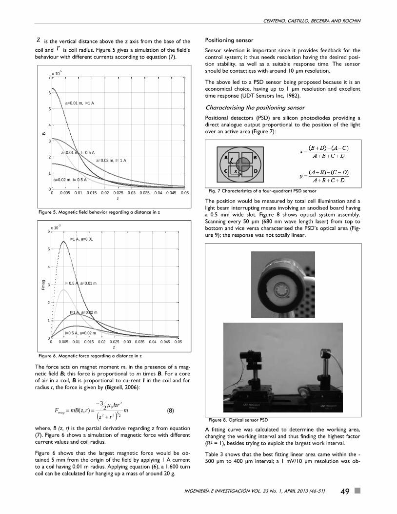
z is the vertical distance above the z axis from the base of the
coil and r is coil radius. Figure 5 gives a simulation of the field’s
behaviour with different currents according to equation (7).
Figure 5. Magnetic field behavior regarding a distance in z
Figure 6. Magnetic force regarding a distance in z
The force acts on magnet moment m, in the presence of a mag-
netic field B; this force is proportional to m times B. For a core
of air in a coil, B is proportional to current I in the coil and for
radius r, the force is given by (Bignell, 2006):
m
rz
IzrrzmBFmag
25
22
2
023
),(
(8)
where, B (z, r) is the partial derivative regarding z from equation
(7). Figure 6 shows a simulation of magnetic force with different
current values and coil radius.
Figure 6 shows that the largest magnetic force would be ob-
tained 5 mm from the origin of the field by applying 1 A current
to a coil having 0.01 m radius. Applying equation (6), a 1,600 turn
coil can be calculated for hanging up a mass of around 20 g.
Positioning sensor
Sensor selection is important since it provides feedback for the
control system; it thus needs resolution having the desired posi-
tion stability, as well as a suitable response time. The sensor
should be contactless with around 10 µm resolution.
The above led to a PSD sensor being proposed because it is an
economical choice, having up to 1 µm resolution and excellent
time response (UDT Sensors Inc, 1982).
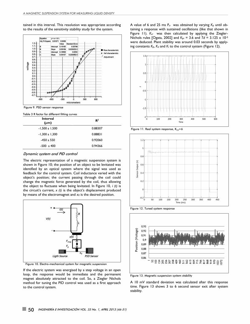
Characterising the positioning sensor
Positional detectors (PSD) are silicon photodiodes providing a
direct analogue output proportional to the position of the light
over an active area (Figure 7):
Fig. 7 Characteristics of a four-quadrant PSD sensor
The position would be measured by total cell illumination and a
light beam interrupting means involving an anodised board having
a 0.5 mm wide slot. Figure 8 shows optical system assembly.
Scanning every 50 µm (680 nm wave length laser) from top to
bottom and vice versa characterised the PSD’s optical area (Fig-
ure 9); the response was not totally linear.
Figure 8. Optical sensor PSD
A fitting curve was calculated to determine the working area,
changing the working interval and thus finding the highest factor
(R2 = 1), besides trying to exploit the largest work interval.
Table 3 shows that the best fitting linear area came within the -
500 µm to 400 µm interval; a 1 mV/10 µm resolution was ob-
0 0.005 0.01 0.015 0.02 0.025 0.03 0.035 0.04 0.045 0.050
1
2
3
4
5
6
7x 10
-5
z
B
a=0.01 m, I=1 A
a=0.02 m, I= 1 A
a=0.01 m, I= 0.5 A
a=0.02 m, I= 0.5 A
0 0.005 0.01 0.015 0.02 0.025 0.03 0.035 0.04 0.045 0.050
1
2
3
4
5
6x 10
-3
z
Fm
ag
I=1 A, a=0.01
I= 0.5 A, a=0.01 m
I=1 A, a=0.02 m
I=0.5 A, a=0.02 m
A MAGNETIC SUSPENSION SYSTEM FOR MEASURING LIQUID DENSITY
INGENIERÍA E INVESTIGACIÓN VOL. 33 No. 1, APRIL 2013 (46-51) 50
tained in this interval. This resolution was appropriate according
to the results of the sensitivity stability study for the system.
Figure 9. PSD sensor response
Table 3 R factor for different fitting curves
Interval
(m) R2
-1,500 a 1,500 0.88307
-1,300 a 1,300 0.88831
-450 a 550 0.92060
-500 a 400 0.94366
Dynamic system and PID control
The electric representation of a magnetic suspension system is
shown in Figure 10; the position of an object to be levitated was
identified by an optical system where the signal was used as
feedback for the control system. Coil inductance varied with the
object’s position; the current passing through the coil could
change the magnetic force generated by the coil, thus allowing
the object to fluctuate when being levitated. In Figure 10, i (t) is
the circuit’s current, x (t) is the object’s displacement produced
by means of the electromagnet and x0 is the desired position.
Figure 10. Electro-mechanical system for magnetic suspension
If the electric system was energised by a step voltage in an open
loop, the response would be immediate and the permanent
magnet absolutely attracted to the coil. So, a Ziegler Nichols
method for tuning the PID control was used as a first approach
to the control system.
A value of 6 and 25 ms Pcr was obtained by varying Kp until ob-
taining a response with sustained oscillations (like that shown in
Figure 11). Kcr was then calculated by applying the Ziegler-
Nichols rules [Ogata, 2002] and Kpr = 3.6 and Td = 3.125 x 10⁻⁵
were deduced. Plant stability was around 0.03 seconds by apply-
ing constants Kp, Kd and Ki to the control system (Figure 12).
Figure 11. Real system response, KCR=6
Figure 12. Tuned system response
Figure 13. Magnetic suspension system stability
A 10 mV standard deviation was calculated after this response
time. Figure 13 shows 3 to 6 second sensor exit after system
stability.
0 100 200 300 400 500 600-2
-1.5
-1
-0.5
0
0.5
1
1.5
Time
z
0 50 100 150 200 250 300 350 400 450-0.2
0
0.2
0.4
0.6
0.8
1
1.2
Time (ms)
Sensor
Outp
ut
(V)
0,86
0,87
0,88
0,89
0,9
0,91
0,92
0,93
1
52
103
154
205
256
307
358
409
460
511
562
613
664
715
766
817
868
919
970
1021
1072
Posi
tion (
Voltag
e)
CENTENO, CASTILLO, BECERRA AND ROCHIN
INGENIERÍA E INVESTIGACIÓN VOL. 33 No. 1, APRIL 2013 (46-51) 51
A ± 10 µm variation led to a 10 mV standard deviation which,
according to the system sensitivity study, was enough to reach 2
x 10-4 relative uncertainty when measuring liquid density. How-
ever, such uncertainty was not enough for the required uncer-
tainty for density reference materials.
Knowing the magnetic suspension system’s transfer function led
to optimising the control loop. The system’s transfer function
was obtained by the least minimum squares’ technique.
The magnetic suspension system’s second order equation was
stated as:
( ) ( ) ( ) ( ) ( )
(9)
Control loop design will form part of future work in this field
and such design will involve using zero power control and the
aforementioned function, seeking better stability.
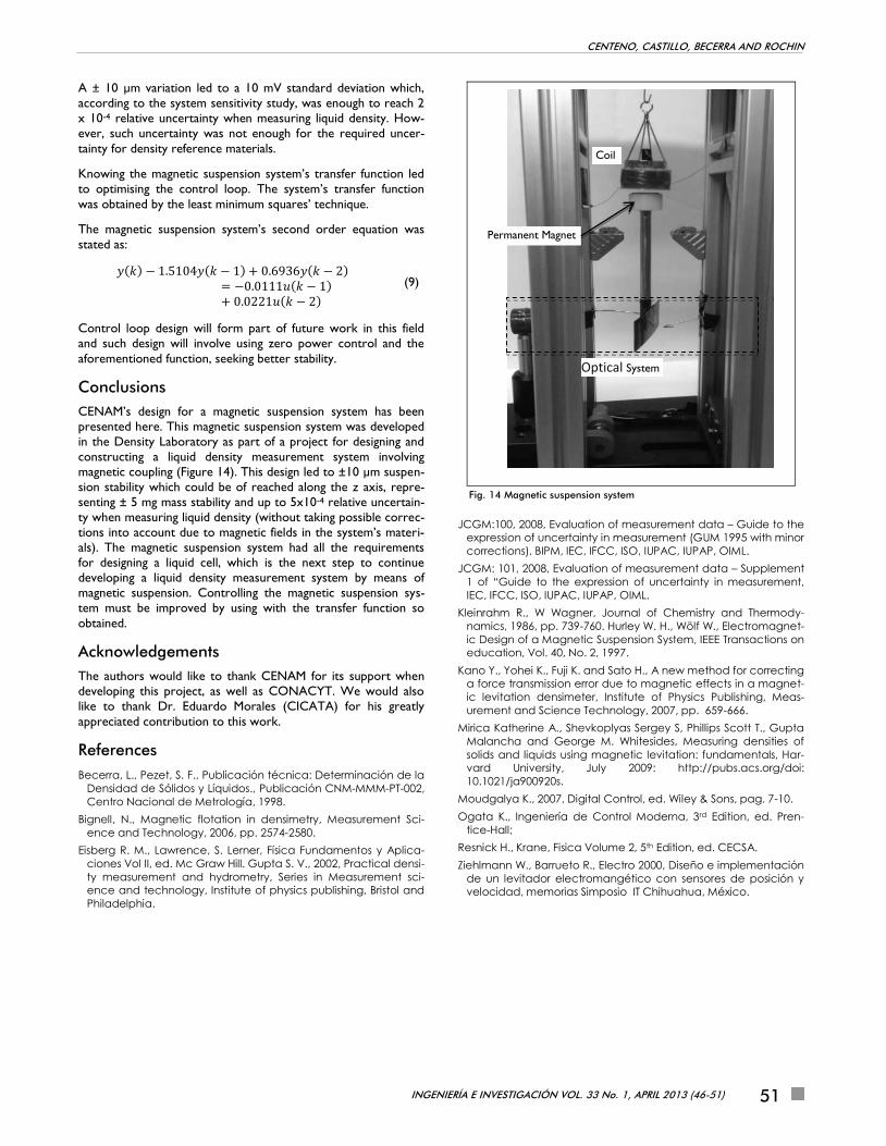
Conclusions
CENAM’s design for a magnetic suspension system has been
presented here. This magnetic suspension system was developed
in the Density Laboratory as part of a project for designing and
constructing a liquid density measurement system involving
magnetic coupling (Figure 14). This design led to ±10 µm suspen-
sion stability which could be of reached along the z axis, repre-
senting ± 5 mg mass stability and up to 5x10⁻⁴ relative uncertain-
ty when measuring liquid density (without taking possible correc-
tions into account due to magnetic fields in the system’s materi-
als). The magnetic suspension system had all the requirements
for designing a liquid cell, which is the next step to continue
developing a liquid density measurement system by means of
magnetic suspension. Controlling the magnetic suspension sys-
tem must be improved by using with the transfer function so
obtained.
Acknowledgements
The authors would like to thank CENAM for its support when
developing this project, as well as CONACYT. We would also
like to thank Dr. Eduardo Morales (CICATA) for his greatly
appreciated contribution to this work.
References
Becerra, L., Pezet, S. F., Publicación técnica: Determinación de la
Densidad de Sólidos y Líquidos., Publicación CNM-MMM-PT-002,
Centro Nacional de Metrología, 1998.
Bignell, N., Magnetic flotation in densimetry, Measurement Sci-
ence and Technology, 2006, pp. 2574-2580.
Eisberg R. M., Lawrence, S. Lerner, Física Fundamentos y Aplica-
ciones Vol II, ed. Mc Graw Hill. Gupta S. V., 2002, Practical densi-
ty measurement and hydrometry, Series in Measurement sci-
ence and technology, Institute of physics publishing, Bristol and
Philadelphia.
Fig. 14 Magnetic suspension system
JCGM:100, 2008, Evaluation of measurement data – Guide to the
expression of uncertainty in measurement (GUM 1995 with minor
corrections), BIPM, IEC, IFCC, ISO, IUPAC, IUPAP, OIML.
JCGM: 101, 2008, Evaluation of measurement data – Supplement
1 of “Guide to the expression of uncertainty in measurement,
IEC, IFCC, ISO, IUPAC, IUPAP, OIML.
Kleinrahm R., W Wagner, Journal of Chemistry and Thermody-
namics, 1986, pp. 739-760. Hurley W. H., Wölf W., Electromagnet-
ic Design of a Magnetic Suspension System, IEEE Transactions on
education, Vol. 40, No. 2, 1997.
Kano Y., Yohei K., Fuji K. and Sato H., A new method for correcting
a force transmission error due to magnetic effects in a magnet-
ic levitation densimeter, Institute of Physics Publishing, Meas-
urement and Science Technology, 2007, pp. 659-666.
Mirica Katherine A., Shevkoplyas Sergey S, Phillips Scott T., Gupta
Malancha and George M. Whitesides, Measuring densities of
solids and liquids using magnetic levitation: fundamentals, Har-
vard University, July 2009: http://pubs.acs.org/doi:
10.1021/ja900920s.
Moudgalya K., 2007, Digital Control, ed. Wiley & Sons, pag. 7-10.
Ogata K., Ingeniería de Control Moderna, 3rd Edition, ed. Pren-
tice-Hall;
Resnick H., Krane, Fisica Volume 2, 5th Edition, ed. CECSA.
Ziehlmann W., Barrueto R., Electro 2000, Diseño e implementación
de un levitador electromangético con sensores de posición y
velocidad, memorias Simposio IT Chihuahua, México.
Coil
Permanent Magnet
Optical System