Embed Size (px)
Citation preview
División de Informática Dpto. de Redes
Implementación de Túneles para IPv6 en Router
Cisco
Integrantes: • Marcelo J. Martínez Vallecillo • Felix Eduardo Sobalvarro Rojas • Jorge Luis Espinoza Lira
Objetivos General
• Conocer el procedimiento para enviar y recibir paquetes IPv6 a través de túneles IPv4.
Objetivos Específicos
• Clasificar y explicar los tipos de túneles existentes. • Conocer las ventajas y las desventajas de estos sistemas.
Introducción
La transición de IPv4 a IPv6 Hoy en día existen mecanismos que pueden ser implementados por hosts y routers IPv6 para mantener la compatibilidad con IPv4 los cuales agilizan la expansión de IPv6 en Internet y facilitan la transición. La clave para una transición exitosa a IPv6 es la compatibilidad con IPv4. Los mecanismos están diseñados para ser empleados por hosts y routers IPv6 que necesitan interactuar con hosts IPv4 y que utilizan la infraestructura de enrutamiento de IPv4. Los mecanismos son los siguientes:
• Dual IP layer (doble capa IP): Consiste en proveer en hosts y routers un soporte completo tanto para IPv6 como para IPv4.
• IPv6−over−IPv4 tunneling (IPv6 sobre IPv4): Consiste en encapsular los paquetes de IPv6
dentro de los headers de IPv4 para transportarlos sobre las estructuras de enrutamiento actuales. Los dos tipos de túneles que se emplean son: configurados y automáticos.
La infraestructura IPv6 esta en una constante evolución. Mientras esta infraestructura se desarrolla y se expande, la infraestructura de enrutamiento existente (IPv4) puede seguir funcionando y ser utilizada para transportar trafico IPv6. Tunneling provee un camino para lograr esto.
Los hosts y routers IPv6/IPv4 pueden pasar datagramas IPv6 sobre regiones de topología de enrutamiento IPv4 encapsulandolos dentro de paquetes IPv4.
Tunneling puede ser usado en una variedad de formas:
• Router-to-Router: Los routers IPv6/IPv4 interconectados con una infraestructura IPv4 pueden pasarse entre sí paquetes IPv6. En este caso el túnel abarca un segmento del trayecto que toma el paquete IPv6.
• Host-to-Router: Los host IPv6/IPv4 pueden pasar paquetes IPv6 por un router IPv6/IPv4 intermediario que sea alcanzable por la infraestructura IPv4. Este tipo de túnel abarca el primer segmento del trayecto del paquete.
• Host-to-Host: Los hosts IPv6/IPv4 interconectados con una infraestructura IPv4 pueden pasarse paquetes IPv6 entre sí. En este caso el túnel abarca el recorrido completo que toman los paquetes.
• Router-to-Host: Los routers IPv6/IPv4 pueden pasar paquetes IPv6 hasta su host IPv6/IPv4 destinatario (final). Este túnel abarca el ultimo segmento del recorrido.
Las técnicas de tunneling se clasifican según el mecanismo por el cual el nodo de encapsulamiento determina la dirección del nodo al final del túnel. En los primeros dos casos (Router-to-Router y Host-to-Router) el paquete IPv6 es pasado (tunneled) a un router. El endpoint de este tipo de túneles es un router intermediario el cual debe desencapsular el paquete IPv6 y reenviarlo a su destino final. Cuando se envían paquetes a un router, el endpoint del túnel es distinto del destino final del paquete que se esta enviando. Así, la dirección del paquete IPv6 que se envía no provee la dirección IPv4 del endpoint del túnel. Por esto, dicha dirección deberá obtenerse de la información de configuración en el nodo que ejecuta el tunneling. Por lo tanto se usa el termino tuneling configurado (configurate tunneling) para describir el tipo de túneles donde el endpoint esta explícitamente configurado.
En los últimos dos casos (Host-to-Host y Router-to-Host) el endpoint del túnel es el nodo al cual el paquete IPv6 esta direccionado. Por lo tanto el endpoint puede ser determinado por la dirección IPv6 de destino del paquete. Si dicha dirección es una dirección IPv6 compatible con IPv4 entonces los últimos 32 bits especifican la dirección del nodo de destino y se puede usar como dirección del endpoint del túnel. De esta forma se evita configurar explícitamente de la dirección del endpoint. Esta técnica es llamada tuneling automático.
Las dos técnicas de tunneling se diferencian principalmente en como se valen para determinar la dirección del endpoint del tunel. La mayor parte de estos mecanismos son lo mismo:
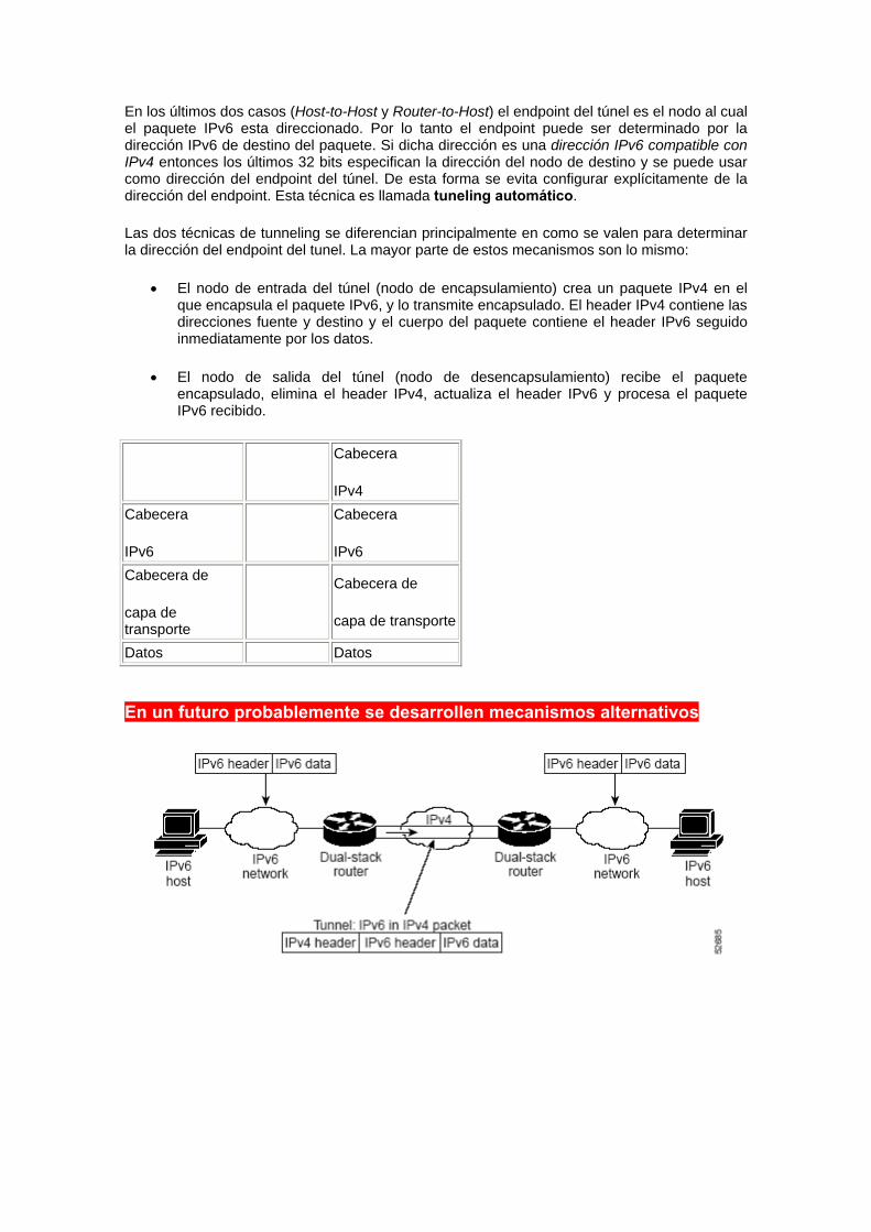
• El nodo de entrada del túnel (nodo de encapsulamiento) crea un paquete IPv4 en el que encapsula el paquete IPv6, y lo transmite encapsulado. El header IPv4 contiene las direcciones fuente y destino y el cuerpo del paquete contiene el header IPv6 seguido inmediatamente por los datos.
• El nodo de salida del túnel (nodo de desencapsulamiento) recibe el paquete encapsulado, elimina el header IPv4, actualiza el header IPv6 y procesa el paquete IPv6 recibido.
Cabecera
IPv4 Cabecera
IPv6
Cabecera
IPv6 Cabecera de
capa de transporte
Cabecera de
capa de transporte
Datos Datos En un futuro probablemente se desarrollen mecanismos alternativos
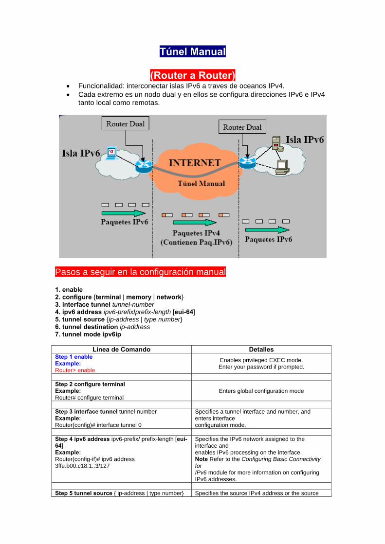
Túnel Manual
(Router a Router) • Funcionalidad: interconectar islas IPv6 a traves de oceanos IPv4. • Cada extremo es un nodo dual y en ellos se configura direcciones IPv6 e IPv4
tanto local como remotas.
Pasos a seguir en la configuración manual 1. enable 2. configure {terminal | memory | network} 3. interface tunnel tunnel-number 4. ipv6 address ipv6-prefix/prefix-length [eui-64] 5. tunnel source {ip-address | type number} 6. tunnel destination ip-address 7. tunnel mode ipv6ip
Línea de Comando Detalles Step 1 enable Example: Router> enable
Enables privileged EXEC mode. Enter your password if prompted.
Step 2 configure terminal Example: Router# configure terminal
Enters global configuration mode
Step 3 interface tunnel tunnel-number Example: Router(config)# interface tunnel 0
Specifies a tunnel interface and number, and enters interface configuration mode.
Step 4 ipv6 address ipv6-prefix/ prefix-length [eui-64] Example: Router(config-if)# ipv6 address 3ffe:b00:c18:1::3/127
Specifies the IPv6 network assigned to the interface and enables IPv6 processing on the interface. Note Refer to the Configuring Basic Connectivity for IPv6 module for more information on configuring IPv6 addresses.
Step 5 tunnel source { ip-address | type number} Specifies the source IPv4 address or the source
Example: Router(config-if)# tunnel source ethernet 0
interface type and number for the tunnel interface. • If an interface is specified, the interface must be configured with an IPv4 address.
Step 6 tunnel destination ip-address Example: Router(config-if)# tunnel destination 192.168.30.1
Specifies the destination IPv4 address or host name for the tunnel interface.
Step 7 tunnel mode ipv6ip Example: Router(config-if)# tunnel mode ipv6ip
Specifies a manual IPv6 tunnel. Note The tunnel mode ipv6ip command specifies IPv6 as the passenger protocol and IPv4 as both the encapsulation and transport protocol for the manual IPv6 tunnel.
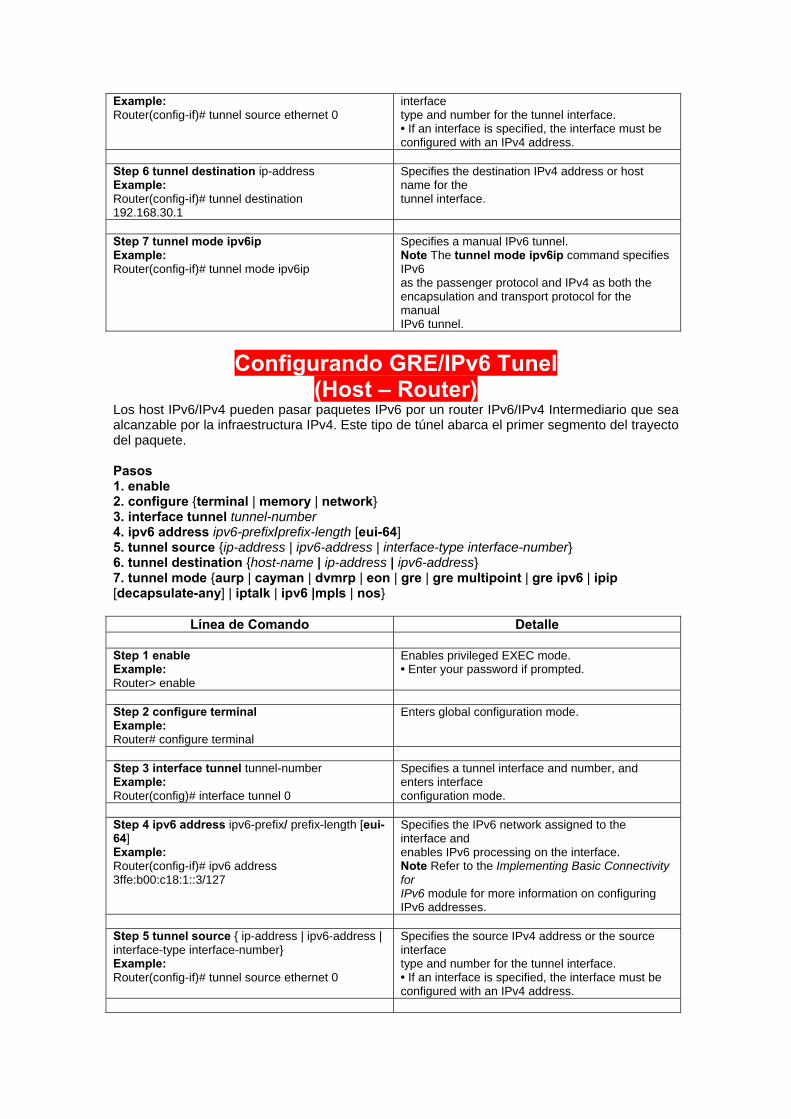
Configurando GRE/IPv6 Tunel
(Host – Router) Los host IPv6/IPv4 pueden pasar paquetes IPv6 por un router IPv6/IPv4 Intermediario que sea alcanzable por la infraestructura IPv4. Este tipo de túnel abarca el primer segmento del trayecto del paquete. Pasos 1. enable 2. configure {terminal | memory | network} 3. interface tunnel tunnel-number 4. ipv6 address ipv6-prefix/prefix-length [eui-64] 5. tunnel source {ip-address | ipv6-address | interface-type interface-number} 6. tunnel destination {host-name | ip-address | ipv6-address} 7. tunnel mode {aurp | cayman | dvmrp | eon | gre | gre multipoint | gre ipv6 | ipip [decapsulate-any] | iptalk | ipv6 |mpls | nos}
Línea de Comando Detalle Step 1 enable Example: Router> enable
Enables privileged EXEC mode. • Enter your password if prompted.
Step 2 configure terminal Example: Router# configure terminal
Enters global configuration mode.
Step 3 interface tunnel tunnel-number Example: Router(config)# interface tunnel 0
Specifies a tunnel interface and number, and enters interface configuration mode.
Step 4 ipv6 address ipv6-prefix/ prefix-length [eui-64] Example: Router(config-if)# ipv6 address 3ffe:b00:c18:1::3/127
Specifies the IPv6 network assigned to the interface and enables IPv6 processing on the interface. Note Refer to the Implementing Basic Connectivity for IPv6 module for more information on configuring IPv6 addresses.
Step 5 tunnel source { ip-address | ipv6-address | interface-type interface-number} Example: Router(config-if)# tunnel source ethernet 0
Specifies the source IPv4 address or the source interface type and number for the tunnel interface. • If an interface is specified, the interface must be configured with an IPv4 address.
Step 6 tunnel destination { host-name | ip-address | ipv6-address} Example: Router(config-if)# tunnel destination 192.168.30.1
Specifies the destination IPv4 address or host name for the tunnel interface.
Step 7 tunnel mode {aurp | cayman | dvmrp | eon | gre | gre multipoint | gre ipv6 | ipip [decapsulate-any] | iptalk | ipv6 |mpls | nos} Example: Router(config-if)# tunnel mode gre ip
Specifies a GRE IPv6 tunnel. Note The tunnel mode gre ip command specifies GRE as the encapsulation protocol for the tunnel. Specifies a GRE IPv6 tunnel. Note The tunnel mode gre ip command specifies GRE as the encapsulation protocol for the tunnel.
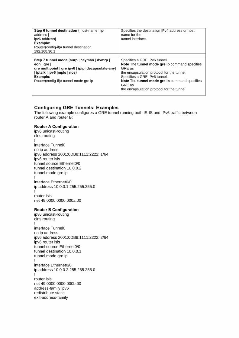
Configuring GRE Tunnels: Examples The following example configures a GRE tunnel running both IS-IS and IPv6 traffic between router A and router B: Router A Configuration ipv6 unicast-routing clns routing ! interface Tunnel0 no ip address ipv6 address 2001:0DB8:1111:2222::1/64 ipv6 router isis tunnel source Ethernet0/0 tunnel destination 10.0.0.2 tunnel mode gre ip ! interface Ethernet0/0 ip address 10.0.0.1 255.255.255.0 ! router isis net 49.0000.0000.000a.00 Router B Configuration ipv6 unicast-routing clns routing ! interface Tunnel0 no ip address ipv6 address 2001:0DB8:1111:2222::2/64 ipv6 router isis tunnel source Ethernet0/0 tunnel destination 10.0.0.1 tunnel mode gre ip ! interface Ethernet0/0 ip address 10.0.0.2 255.255.255.0 ! router isis net 49.0000.0000.000b.00 address-family ipv6 redistribute static exit-address-family
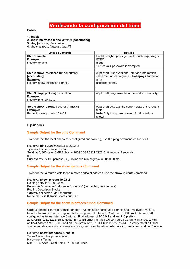
Verificando la configuración del túnel Pasos
1. enable 2. show interfaces tunnel number [accounting] 3. ping [protocol] destination 4. show ip route [address [mask]]
Linea de Comando Detalles Step 1 enable Example: Router> enable
Enables higher privilege levels, such as privileged EXEC mode. • Enter your password if prompted.
Step 2 show interfaces tunnel number [accounting] Example: Router# show interfaces tunnel 0
(Optional) Displays tunnel interface information. • Use the number argument to display information for a specified tunnel.
Step 3 ping [ protocol] destination Example: Router# ping 10.0.0.1
(Optional) Diagnoses basic network connectivity.
Step 4 show ip route [ address [ mask]] Example: Router# show ip route 10.0.0.2
(Optional) Displays the current state of the routing table. Note Only the syntax relevant for this task is shown.
Ejemplos Sample Output for the ping Command To check that the local endpoint is configured and working, use the ping command on Router A: RouterA# ping 2001:0DB8:1111:2222::2 Type escape sequence to abort. Sending 5, 100-byte ICMP Echos to 2001:0DB8:1111:2222::2, timeout is 2 seconds: !!!!! Success rate is 100 percent (5/5), round-trip min/avg/max = 20/20/20 ms Sample Output for the show ip route Command To check that a route exists to the remote endpoint address, use the show ip route command: RouterA# show ip route 10.0.0.2 Routing entry for 10.0.0.0/24 Known via "connected", distance 0, metric 0 (connected, via interface) Routing Descriptor Blocks: * directly connected, via Ethernet0/0 Route metric is 0, traffic share count is 1 Sample Output for the show interfaces tunnel Command Using a generic example suitable for both IPv6 manually configured tunnels and IPv6 over IPv4 GRE tunnels, two routers are configured to be endpoints of a tunnel. Router A has Ethernet interface 0/0 configured as tunnel interface 0 with an IPv4 address of 10.0.0.1 and an IPv6 prefix of 2001:0DB8:1111:2222::1/64. Router B has Ethernet interface 0/0 configured as tunnel interface 1 with an IPv4 address of 10.0.0.2 and an IPv6 prefix of 2001:0DB8:1111:2222::2/64. To verify that the tunnel source and destination addresses are configured, use the show interfaces tunnel command on Router A. RouterA# show interfaces tunnel 0 Tunnel0 is up, line protocol is up Hardware is Tunnel MTU 1514 bytes, BW 9 Kbit, DLY 500000 usec,
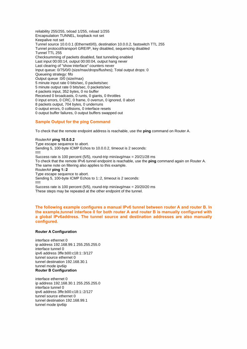
reliability 255/255, txload 1/255, rxload 1/255 Encapsulation TUNNEL, loopback not set Keepalive not set Tunnel source 10.0.0.1 (Ethernet0/0), destination 10.0.0.2, fastswitch TTL 255 Tunnel protocol/transport GRE/IP, key disabled, sequencing disabled Tunnel TTL 255 Checksumming of packets disabled, fast tunneling enabled Last input 00:00:14, output 00:00:04, output hang never Last clearing of "show interface" counters never Input queue: 0/75/0/0 (size/max/drops/flushes); Total output drops: 0 Queueing strategy: fifo Output queue :0/0 (size/max) 5 minute input rate 0 bits/sec, 0 packets/sec 5 minute output rate 0 bits/sec, 0 packets/sec 4 packets input, 352 bytes, 0 no buffer Received 0 broadcasts, 0 runts, 0 giants, 0 throttles 0 input errors, 0 CRC, 0 frame, 0 overrun, 0 ignored, 0 abort 8 packets output, 704 bytes, 0 underruns 0 output errors, 0 collisions, 0 interface resets 0 output buffer failures, 0 output buffers swapped out Sample Output for the ping Command To check that the remote endpoint address is reachable, use the ping command on Router A. RouterA# ping 10.0.0.2 Type escape sequence to abort. Sending 5, 100-byte ICMP Echos to 10.0.0.2, timeout is 2 seconds: !!!!! Success rate is 100 percent (5/5), round-trip min/avg/max = 20/21/28 ms To check that the remote IPv6 tunnel endpoint is reachable, use the ping command again on Router A. The same note on filtering also applies to this example. RouterA# ping 1::2 Type escape sequence to abort. Sending 5, 100-byte ICMP Echos to 1::2, timeout is 2 seconds: !!!!! Success rate is 100 percent (5/5), round-trip min/avg/max = 20/20/20 ms These steps may be repeated at the other endpoint of the tunnel. The following example configures a manual IPv6 tunnel between router A and router B. In the example,tunnel interface 0 for both router A and router B is manually configured with a global IPv6address. The tunnel source and destination addresses are also manually configured. Router A Configuration interface ethernet 0 ip address 192.168.99.1 255.255.255.0 interface tunnel 0 ipv6 address 3ffe:b00:c18:1::3/127 tunnel source ethernet 0 tunnel destination 192.168.30.1 tunnel mode ipv6ip Router B Configuration interface ethernet 0 ip address 192.168.30.1 255.255.255.0 interface tunnel 0 ipv6 address 3ffe:b00:c18:1::2/127 tunnel source ethernet 0 tunnel destination 192.168.99.1 tunnel mode ipv6ip
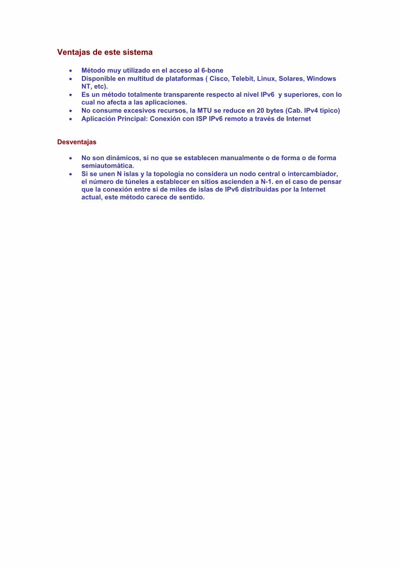
Ventajas de este sistema
• Método muy utilizado en el acceso al 6-bone • Disponible en multitud de plataformas ( Cisco, Telebit, Linux, Solares, Windows
NT, etc). • Es un método totalmente transparente respecto al nivel IPv6 y superiores, con lo
cual no afecta a las aplicaciones. • No consume excesivos recursos, la MTU se reduce en 20 bytes (Cab. IPv4 típico) • Aplicación Principal: Conexión con ISP IPv6 remoto a través de Internet
Desventajas
• No son dinámicos, si no que se establecen manualmente o de forma o de forma semiautomática.
• Si se unen N islas y la topología no considera un nodo central o intercambiador, el número de túneles a establecer en sitios ascienden a N-1. en el caso de pensar que la conexión entre si de miles de islas de IPv6 distribuidas por la Internet actual, este método carece de sentido.
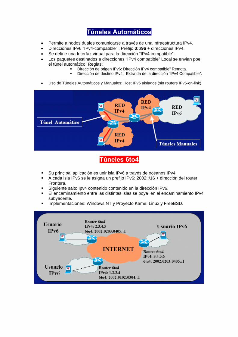
Túneles Automáticos
• Permite a nodos duales comunicarse a través de una infraestructura IPv4. • Direcciones IPv6 “IPv4-compatible” : Prefijo 0::/96 + direcciones IPv4. • Se define una Interfaz virtual para la dirección “IPv4 compatible”. • Los paquetes destinados a direcciones “IPv4 compatible” Local se envian poe
el túnel automático. Reglas: Dirección de origen IPv6: Dirección IPv4 compatible” Remota. Dirección de destino IPv4: Extraída de la dirección “IPv4 Compatible”.
• Uso de Túneles Automáticos y Manuales: Host IPv6 aislados (sin routers IPv6-on-link)
Túneles 6to4
Su principal aplicación es unir isla IPv6 a través de océanos IPv4. A cada isla IPv6 se le asigna un prefijo IPv6: 2002::/16 + dirección del router
Frontera. Siguiente salto Ipv4 contenido contenido en la dirección IPv6. El encaminamiento entre las distintas islas se poya en el encaminamiento IPv4
subyacente. Implementaciones: Windows NT y Proyecto Kame: Linux y FreeBSD.
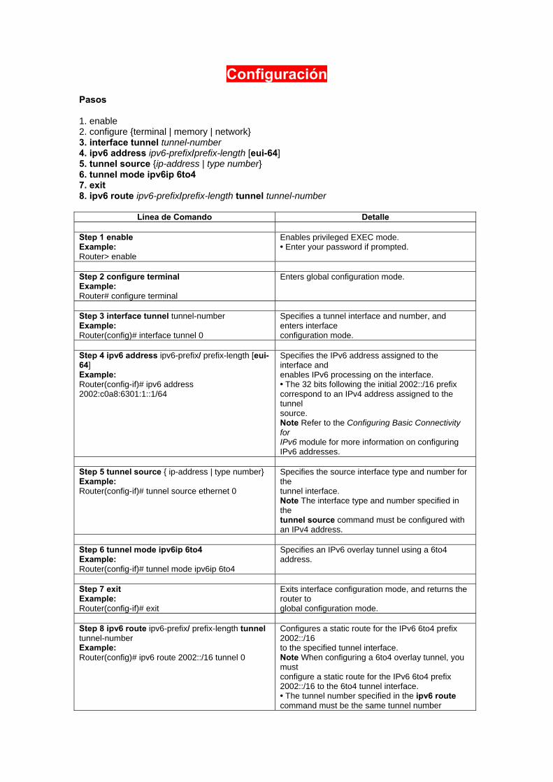
Configuración
Pasos 1. enable 2. configure {terminal | memory | network} 3. interface tunnel tunnel-number 4. ipv6 address ipv6-prefix/prefix-length [eui-64] 5. tunnel source {ip-address | type number} 6. tunnel mode ipv6ip 6to4 7. exit 8. ipv6 route ipv6-prefix/prefix-length tunnel tunnel-number
Línea de Comando Detalle Step 1 enable Example: Router> enable
Enables privileged EXEC mode. • Enter your password if prompted.
Step 2 configure terminal Example: Router# configure terminal
Enters global configuration mode.
Step 3 interface tunnel tunnel-number Example: Router(config)# interface tunnel 0
Specifies a tunnel interface and number, and enters interface configuration mode.
Step 4 ipv6 address ipv6-prefix/ prefix-length [eui-64] Example: Router(config-if)# ipv6 address 2002:c0a8:6301:1::1/64
Specifies the IPv6 address assigned to the interface and enables IPv6 processing on the interface. • The 32 bits following the initial 2002::/16 prefix correspond to an IPv4 address assigned to the tunnel source. Note Refer to the Configuring Basic Connectivity for IPv6 module for more information on configuring IPv6 addresses.
Step 5 tunnel source { ip-address | type number} Example: Router(config-if)# tunnel source ethernet 0
Specifies the source interface type and number for the tunnel interface. Note The interface type and number specified in the tunnel source command must be configured with an IPv4 address.
Step 6 tunnel mode ipv6ip 6to4 Example: Router(config-if)# tunnel mode ipv6ip 6to4
Specifies an IPv6 overlay tunnel using a 6to4 address.
Step 7 exit Example: Router(config-if)# exit
Exits interface configuration mode, and returns the router to global configuration mode.
Step 8 ipv6 route ipv6-prefix/ prefix-length tunnel tunnel-number Example: Router(config)# ipv6 route 2002::/16 tunnel 0
Configures a static route for the IPv6 6to4 prefix 2002::/16 to the specified tunnel interface. Note When configuring a 6to4 overlay tunnel, you must configure a static route for the IPv6 6to4 prefix 2002::/16 to the 6to4 tunnel interface. • The tunnel number specified in the ipv6 route command must be the same tunnel number
specified in the interface tunnel command. Command or Action Purpose
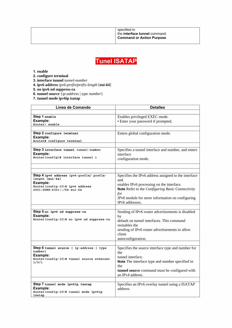
Tunel ISATAP
1. enable 2. configure terminal 3. interface tunnel tunnel-number 4. ipv6 address ipv6-prefix/prefix-length [eui-64] 5. no ipv6 nd suppress-ra 6. tunnel source {ip-address | type number} 7. tunnel mode ipv6ip isatap
Linea de Comando Detalles
Step 1 enable Example: Router> enable
Enables privileged EXEC mode. • Enter your password if prompted.
Step 2 configure terminal Example: Router# configure terminal
Enters global configuration mode.
Step 3 interface tunnel tunnel-number Example: Router(config)# interface tunnel 1
Specifies a tunnel interface and number, and enters interface configuration mode.
Step 4 ipv6 address ipv6-prefix/ prefix-length [eui-64]
Example: Router(config-if)# ipv6 address 2001:0DB8:6301::/64 eui-64
Specifies the IPv6 address assigned to the interface and enables IPv6 processing on the interface. Note Refer to the Configuring Basic Connectivity for IPv6 module for more information on configuring IPv6 addresses.
Step 5 no ipv6 nd suppress-ra Example: Router(config-if)# no ipv6 nd suppress-ra
Sending of IPv6 router advertisements is disabled by default on tunnel interfaces. This command reenables the sending of IPv6 router advertisements to allow client autoconfiguration.
Step 6 tunnel source { ip-address | type number}
Example: Router(config-if)# tunnel source ethernet 1/0/1
Specifies the source interface type and number for the tunnel interface. Note The interface type and number specified in the tunnel source command must be configured with an IPv4 address.
Step 7 tunnel mode ipv6ip isatap Example: Router(config-if)# tunnel mode ipv6ip isatap
Specifies an IPv6 overlay tunnel using a ISATAP address.
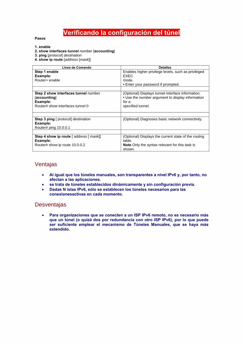
Verificando la configuración del túnel Pasos
1. enable 2. show interfaces tunnel number [accounting] 3. ping [protocol] destination 4. show ip route [address [mask]]
Linea de Comando Detalles Step 1 enable Example: Router> enable
Enables higher privilege levels, such as privileged EXEC mode. • Enter your password if prompted.
Step 2 show interfaces tunnel number [accounting] Example: Router# show interfaces tunnel 0
(Optional) Displays tunnel interface information. • Use the number argument to display information for a specified tunnel.
Step 3 ping [ protocol] destination Example: Router# ping 10.0.0.1
(Optional) Diagnoses basic network connectivity.
Step 4 show ip route [ address [ mask]] Example: Router# show ip route 10.0.0.2
(Optional) Displays the current state of the routing table. Note Only the syntax relevant for this task is shown.
Ventajas
• Al igual que los túneles manuales, son transparentes a nivel IPv6 y, por tanto, no afectan a las aplicaciones.
• se trata de túneles establecidos dinámicamente y sin configuración previa. • Dadas N islas IPv6, sólo se establecen los túneles necesarios para las
conexionesactivas en cada momento. Desventajas
• Para organizaciones que se conecten a un ISP IPv6 remoto, no es necesario más que un túnel (o quizá dos por redundancia con otro ISP IPv6), por lo que puede ser suficiente emplear el mecanismo de Túneles Manuales, que se haya más extendido.
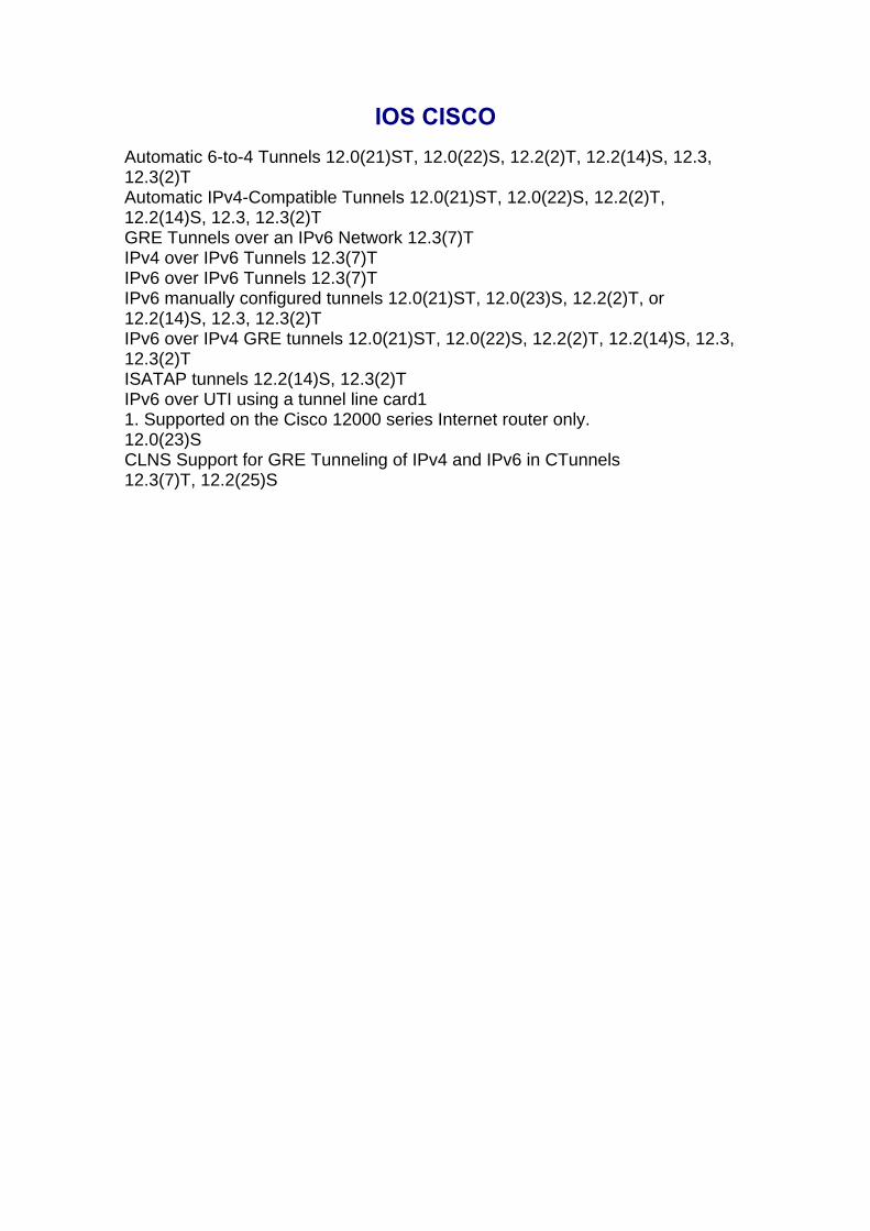
IOS CISCO Automatic 6-to-4 Tunnels 12.0(21)ST, 12.0(22)S, 12.2(2)T, 12.2(14)S, 12.3, 12.3(2)T Automatic IPv4-Compatible Tunnels 12.0(21)ST, 12.0(22)S, 12.2(2)T, 12.2(14)S, 12.3, 12.3(2)T GRE Tunnels over an IPv6 Network 12.3(7)T IPv4 over IPv6 Tunnels 12.3(7)T IPv6 over IPv6 Tunnels 12.3(7)T IPv6 manually configured tunnels 12.0(21)ST, 12.0(23)S, 12.2(2)T, or 12.2(14)S, 12.3, 12.3(2)T IPv6 over IPv4 GRE tunnels 12.0(21)ST, 12.0(22)S, 12.2(2)T, 12.2(14)S, 12.3, 12.3(2)T ISATAP tunnels 12.2(14)S, 12.3(2)T IPv6 over UTI using a tunnel line card1 1. Supported on the Cisco 12000 series Internet router only. 12.0(23)S CLNS Support for GRE Tunneling of IPv4 and IPv6 in CTunnels 12.3(7)T, 12.2(25)S