Embed Size (px)
Citation preview

MI03102-04 11/2016

INTRODUCCIÓNAgradecemos su deferencia hacia nuestra marca y esperamos le sea de gran utilitdad la pantalla desoldadura que acaba de adquirir. El presente manual de instrucciones contiene las advertencias nece-sarias para una correcta utilización dentro de las máximas condiciones de seguridad para el operario.Los filtros de soldadura SOLTER deben ser empleados por personal experto que conozca y com-prenda los riesgos involucrados en la utilización de las mismas. En caso de incomprensión o dudasobre este manual les rogamos que se ponga en contacto con nosotros. La manipulación del filtro desoldadura conlleva un peligro importante de lesión. Rogamos se abstenga de efectuar cualquier mani-pulación en el filtro o casco. Sólo personal técnicamente preparado puede realizarlo.SOLTER Soldadura, S.L. declina toda responabilidad por prácticas negligentes en la utilización y/omanipulación. Este manual debe adjuntarse y conservarse con el modelo de filtro adquirido.Estos filtros están diseñados y aprobados de acuerdo con la Norma Europea EN 379.Es responsabilidad de las personas que los utilicen y reparen que el producto no deje de cumplir losrequisitos de las normas mencionadas.
ANTES DE EMPEZAR A SOLDARAntes de usar cualquiera de los filtros de soldadura asegúrese de retirar los films de protección co-rrespondientes, mantenga limpia el área de visión y la parte frontal del filtro ya que ahí se encuentranlos sensores que se ocupan del oscurecimiento del filtro.Inspeccionar todas las partes operativas antes de usar la pantalla y comprobar que no existen signosde deterioro. Cualquier parte deteriorada debe sustituirse inmediatamente antes de su utilización. Ve-rificar el funcionamiento del filtro antes de cada uso.Asegúrese también de que la sujeción del mismo a la pantalla de protección es correcta para evitarque el mismo se pueda desprender ante cualquier impacto pudiendo provocar daños personales alusuario.En caso de que el DIN de oscurecimiento del filtro sea regulable ajústelo correctamente antes decualquier aplicación, para saber el grado adecuado para todas las aplicaciones consulte el apartadoTABLA DE ELECCIÓN DE FILTROS SEGÚN APLICACIÓN del manual de la pantalla de protección.
CARACTERÍSTICAS TÉCNICAS
MODELO OPTIMATIC 100 OPTIMATIC 55 OPTIMATIC 50Policarbonato 110x90x8mm 110x90x8mm 110x90x8mm
Área de visión 96x39mm 96x39mm 91x39mm
CE 1/1/1/2 1/1/1/2 1/1/1/2
Oscurecimiento Ajustable (DIN 4/9-13) Ajustable (DIN 4/9-13) Fijo (DIN 11)
Tipo de AlimentaciónPlacas solares y 1 pilarecambiable CR 2032
Placas solares Placas solares
On / Off Automático Automático Automático
SensibilidadAjustableBaja (LOW)Alta (HIGH)
AjustableBaja (LOW)Alta (HIGH)
Manual (Interior)
Velocidad Oscuro / Claro0,1s MIN1,0s MAX
0,1s MIN1,0s MAX
0,1s SLOW0,8s FAST
RangoTemperatura de trabajo - 10ºC a + 60ºC - 10ºC a + 60ºC - 10ºC a + 60ºC
Peso 0,8 Kg 0,75 Kg 0,75 Kg
SOLTER SOLDADURA S.L.

PARTES DE LOS FILTROS
Todos los filtros vienen marcados tal como indica el certificado CE de cada modelo. En este marcajese especifica con el primer número el grado de protección DIN que tiene el filtro cuando está en es-tado abierto (claro), el siguiente número indica el grado DIN en estado cerrado (oscuro) indicando elgrado mínimo y el máximo. El símbolo que hay entre los dos numeros nos indica si el ajuste del gradoDIN es manual o automático. Los tres siguientes números nos indican el tipo de óptica, la dispersiónde luz del filtro y la homogeneidad de la visión del filtro según normativa.Los tres numeros siguientes indican la Normativa Europea con la que cumple el filtro.
AJUSTES DE LOS FILTROS
En el modelo OPTIMATIC 100 podemos ajustar el grado DIN manualmente.El ajuste del grado DIN dependerá de la aplicación de la cual nos queramos proteger y de su poten-cia. El grado DIN es el grado de oscuridad del filtro durante el proceso de soldadura.SensibilidadAjusta la intensidad de luz necessaria para que el filtro pase de estado abierto a estado cerrado (os-curo). La posición LOW la sensibilidad a la luz es baja, en posición HIGH la sensibilidad a la luz esalta.RetrasoAjusta el tiempo que tarda el filtro en volver a estado abierto (claro) original una vez finalizado el pro-ceso de soldadura. Para el modelo OPTIMATIC 50 la posición SLOW el retraso es de 0,1s, en posi-
PARTE FRONTAL OPTIMATIC 100
OPTIMATIC 55 OPTIMATIC 50
1-Marcaje segun normativa CE 2- Ajuste sensibilidad3- Ajuste del retraso 4- Pila intercambiable CR 20325- Oscurecimiento
SOLTER SOLDADURA S.L.

ción FAST el retraso es de 0,8s. Para los modelos OPTIMATIC 100 / 55 el retraso se puede regulardesde 0,1s hasta 1,0s.Funciones del filtroAlgunos f ltros permiten operar en dos modos de funcionamiento: Soldadura o amolado.Amolado: Se usa para aplicaciones de amolado de materiales. En este modo, la función de oscureci-miento está apagado. La protección está jado en estado claro, lo que permite tener una visión claracon la seguridad de que la máscara protegerá la cara de cualquier posible daño.
Soldadura: Se usa para la mayoría de aplciaciones de soldadura. En este modo, la función de oscure-cimiento está encendida. En el momento en el que perciba un ópticamente un arco, seleccione elnivel de protección, el tiempo de retardo y el nivel de sensibilidad adecuado.
AJUSTE DEL GRADO DE PROTECCIÓNEn caso de disponer de un filtro con DIN regulable ajustar el grado según la aplicación de la cual nosqueremos proteger. Ver la siguiente tabla.
El modo amolado está pensado para realizar trabajos de amolado, no de soldadura.Antes de volver a soldar asegúrese de volver a de jar la perilla en la posición de soldadura.
TABLA PARA ELECCION DE FILTROS SEGUN APLICACIÓN
CORRIENTEEN
AMPERIOS
CORTEDE
PLASMA
ELECTRO-DOS RE-VESTIDOS
MIGMETALESPESADOS
MIGALEACIONESLIGERAS
TIG MAGARCO /AIRE
SOLDADURADE PLASMA
0,25
TONO 8
TONO 8
TONO 2,50,5 TONO 30,75 TONO 41 TONO 52,5 TONO 65 TONO 710 TONO 815 TONO 8 TONO 9 TONO 920 TONO 1030 TONO 9 TONO 1040 TONO 1160
TONO 11
TONO 10 TONO 11 TONO 980
TONO 12100
TONO 11
TONO 10TONO 12 TONO 10
125TONO 11150 TONO 11
TONO 13TONO 11 TONO 10
TONO 13175
TONO 12200
TONO 12 TONO 12
TONO 12 TONO 12 TONO 11225250
TONO 13
TONO 14
TONO 13TONO 12
TONO 14
275
TONO 13300 TONO 13350
TONO 13 TONO 13TONO 14400
TONO 14TONO 14
450
500TONO 15 TONO 15 TONO 15
TONO 14 TONO 14 TONO 15
SOLTER SOLDADURA S.L.

AJUSTE DEL ARNESAltura del arnes (Posicion W)Ajuste el arnes en la profundidad adecuada en la cabeza para assegurar un equilibrio correcto y esta-ble.Estrechar el arnes (Posicion Y)Pulse el boton de ajuste de la parte trasera del arnes y gire hacia la derecha o la izquierda hasta laposición adecuada.Ajustar distancia (Posicion Z)Ajuste la distancia entre la cara y la lente aflojando por igual las dos tuercas exteriores y presionehacia adentro para liberarlo de las ranuras de ajuste.Ajuste del angulo (Podicion X)Cuatro pernos en el lado derecho superior del arnés proporcionan un ajuste para la futura inclinación-del casco. Para ajustar, afloje la perilla de ajuste del lado derecho, a continuación, levante la pestañadel brazo de control y muevelo a la posición deseada y finalmente vuelva a apretar la perilla de ajuste.
POSIBLES ANOMALÍAS
PROBLEMA POSIBLES SOLUCIONES
Oscurecido irregular del filtroLa cinta de ajuste ha sido posicionada incorrecta-mente o el ángulo del casco respecto a nuestraárea de visión no es el adecuado.
El filtro no se oscurece o parpadea(filtros automáticos)
El filtro protector frontal está dañado o en mal es-tado.Los sensores están sucios.
La corriente de soldadura es demasiado baja.
Respuesta del filtro lenta (filtros automáticos) La temperatura de trabajo es demasiado baja.
Visión insuficiente
Los filtros protectores frontal o posterior estánsucios.
Índice de protección incorrecto.Insuficiente luz en el ambiente de trabajo.
SOLTER SOLDADURA S.L.

DESPIECE
OPTIMATIC 10005904
05901
05900
05902
05899
OPTIMATIC 50
OPTIMATIC 5505904
05901
05900
05902
05898 (50)
05893 (55)
SOLTER SOLDADURA S.L.

INTRODUCTIONThank you for choosing one of our products. We hope you will find this welding screen highly useful.This manual contains the necessary safety warnings and precautions for the correct use of this pro-duct to grant maximum security level for the operator.SOLTER welding filters must only be used by qualified personnel who knows and understands therisks entailed in an improper use of the same.Should any doubt arise regarding this manual, please do not hesitate to contact us.Modifications to the welding filter can result in serious injury.Do not make any modifications to either the filter or the rest of the helmet.Modifications should only beundertaken by qualified technicians.SOLTER Soldadura, S.L. declines all responsibility arising from the misuse and/or improper operationof this product. This manual must accompany the model of the filter that you have purchased and mustbe saved for future reference.These filters are designed and certified in full conformity with EN 379 safety standards.The responsibility for ensuring that this product continues to meet the requirements of the related stan-dards lies with the people that use and repair it.
BEFORE WELDINGBefore using any of the welding filters provided remove the protection film from both sides of the frontlens. Keep the work area clean. Always keep the front lens cover clean. The sensors that cause the fil-ter to darken are located here.Before using the screen, check all operating parts and make sure there are no signs of wear or da-mage. Any part that is damaged should be replaced immediately before use. Test the helmet filter be-fore each use.Ensure that the filter is properly fixed to the protection screen in order to avoid it from detaching in theface of any impact, exposing the user to the risk of personal injury.In case of DIN adjustable darkening filter, select the appropriate shade before each use. Check theSHADE GUIDE TABLE on the protection screen’s manual.
TECHNICAL SPECIFICATIONS
MODEL OPTIMATIC 100 OPTIMATIC 55 OPTIMATIC 50Cartridge Size 110x90x8mm 110x90x8mm 110x90x8mm
Viewing Area 96x39mm 96x39mm 91x39mm
CE 1/1/1/2 1/1/1/2 1/1/1/2
Shade Variable Ajustable (DIN 4/9-13) Ajustable (DIN 4/9-13) Fixed (DIN 11)
Power SupplySolar Panels and 1
replaceable batt CR 2032Solar Panels Solar Panels
On / Off Automatic Automatic Automatic
SensitivityAdjustable(LOW)(HIGH)
Adjustable(LOW)(HIGH)
Manual (Interior)
Delay Time0,1s MIN1,0s MAX
0,1s MIN1,0s MAX
0,1s SLOW0,8s FAST
Operating Temp. - 10ºC a + 60ºC - 10ºC a + 60ºC - 10ºC a + 60ºC
Weight 0,8 Kg 0, 75Kg 0,75 Kg
SOLTER SOLDADURA S.L.
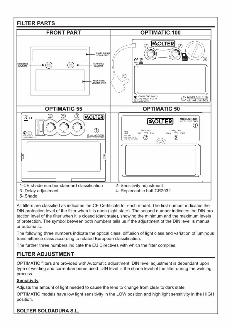
FILTER PARTS
All filters are classified as indicates the CE Certificate for each model. The first number indicates theDIN protection level of the filter when it is open (light state). The second number indicates the DIN pro-tection level of the filter when it is closed (dark state), showing the minimum and the maximum levelsof protection. The symbol between both numbers tells us if the adjustment of the DIN level is manualor automatic.
The following three numbers indicate the optical class, diffusion of light class and variation of luminoustransmittance class according to related European classification.
The further three numbers indicate the EU Directives with which the filter complies.
FILTER ADJUSTMENT
OPTIMATIC filters are provided with Automatic adjustment. DIN level adjustment is dependant upontype of welding and current/amperes used. DIN level is the shade level of the filter during the weldingprocess.
Sensitivity
Adjusts the amount of light needed to cause the lens to change from clear to dark state.
OPTIMATIC models have low light sensitivity in the LOW position and high light sensitivity in the HIGHposition.
FRONT PART OPTIMATIC 100
OPTIMATIC 55 OPTIMATIC 50
1-CE shade number standard classification 2- Sensitivity adjustment3- Delay adjustment 4- Repleceable batt CR20325- Shade
SOLTER SOLDADURA S.L.
Delay
Adjusts the speed at which the welding filter returns to clear state once the welding process is over.
OPTIMATIC 50 models, the position SLOW the DELAY is 0,1s, and the position FAST the DELAY is0,8s. For the OPTIMATIC 100 / 55 models the DELAY you can regulate from 0,1s to 1,0s.
Filter functionsFor some filters ,two modes of operation can be selected : welding or grinding.Grinding mode: Used for metal grinding applications. In this mode the shade function is turned off.The shade is fixed in the light state that all owing a clear view to grind a weld with the helmet providingface protection.
Welding mode: Used for most welding applications. In this mode the shade function is turned on.When it optically senses a welding arc, please select a suitable shade level, delay time and sensitivityas required.
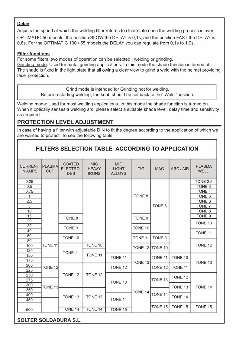
PROTECTION LEVEL ADJUSTMENTIn case of having a filter with adjustable DIN to fit the degree according to the application of which weare wanted to protect. To see the following table.
Grind mode is intended for Grinding not for welding.Before restarting welding, the knob should be set back to the“ Weld ”position.
FILTERS SELECTION TABLE ACCORDING TO APPLICATION
CURRENTIN AMPS
PLASMACUT
COATEDELECTRO-
DES
MIGHEAVYIRONS
MIGLIGHTALLOYS
TIG MAG ARC / AIRPLASMAWELD
0,25
TONE 8
TONE 8
TONE 2,50,5 TONE 30,75 TONE 41 TONE 52,5 TONE 65 TONE 710 TONE 815 TONE 8 TONE 9 TONE 920 TONE 1030 TONE 9 TONE 1040 TONE 1160
TONE 11
TONE 10 TONE 11 TONE 980
TONE 12100
TONE 11
TONE 10TONE 12 TONE 10
125TONE 11150 TONE 11
TONE 13TONE 11 TONE 10
TONE 13175
TONE 12200
TONE 12 TONE 12
TONE 12 TONE 12 TONE 11225250
TONE 13
TONE 14
TONE 13TONE 12
TONE 14
275
TONE 13300 TONE 13350
TONE 13 TONE 13TONE 14400
TONE 14TONE 14
450
500TONE 15 TONE 15 TONE 15
TONE 14 TONE 14 TONE 15
SOLTER SOLDADURA S.L.
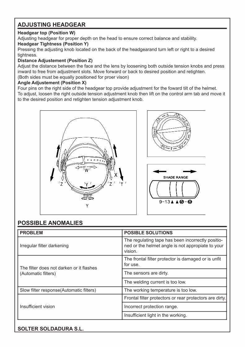
ADJUSTING HEADGEARHeadgear top (Position W)Adjusting headgear for proper depth on the head to ensure correct balance and stability.Headgear Tightness (Position Y)Pressing the adjusting knob located on the back of the headgearand turn left or right to a desiredtightness.Distance Adjustement (Position Z)Adjust the distance between the face and the lens by loosening both outside tension knobs and pressinward to free from adjustment slots. Move forward or back to desired position and retighten.(Both sides must be equally positioned for proer vison)Angle Adjustement (Position X)Four pins on the right side of the headgear top provide adjustment for the foward tilt of the helmet.To adjust, loosen the right outside tension adjustment knob then lift on the control arm tab and move itto the desired position and retighten tension adjustment knob.
POSSIBLE ANOMALIES
PROBLEM POSIBLE SOLUTIONS
Irregular filter darkeningThe regulating tape has been incorrectly positio-ned or the helmet angle is not appropiate to yourvision.
The filter does not darken or it flashes(Automatic filters)
The frontal filter protector is damaged or is unfitfor use.
The sensors are dirty.
The welding current is too low.
Slow filter response(Automatic filters) The working temperature is too low.
Insufficient vision
Frontal filter protectors or rear protectors are dirty.
Incorrect protection range.
Insufficient light in the working.
SOLTER SOLDADURA S.L.

EXPLODED DIAGRAMS
OPTIMATIC 10005904
05901
05900
05902
05899
OPTIMATIC 50
OPTIMATIC 5505904
05901
05900
05902
05898 (50)
05893 (55)
SOLTER SOLDADURA S.L.

DECLARATION OF CONFORMITY DECLARACION DE CONFORMIDADDECLARACIÓ DE CONFORMITATDECLARATION DE CONFORMITEDECLARAÇÃO DE CONFORMIDADEKONFORMITATSERKLARUNG
SOLTER SOLDADURA, S. L.We hereby state that the machine type: / Se declara que el aparato tipo: / És declara que l’aparelltipus: / On ne déclare que la machine type: / Se declara que el aparato tipo: / Die Maschine Typ:
ADF-510G / ADF-200F / ADF-500I
Serial Number: / Número de serie: / Nombre de sèrie: / Numéro de série : / Número de série: / Serien-nummer:
ALL NUMBERSIs in compliance with the directives: / Es conforme a las directivas: / Es conforme a les directives: / Ilest conforme aux directives: / É de acordo com as directivas: / Entspricht den Richtlinien:
2006/95/CE (LVD, EMC), 2002/95/EC (ROHS)2002/96/EC (WEE), 89/686/CEE
And that the following standards apply: / Y que se han aplicado las normas: / I que s’han aplicat lesnormes: / Et qu`on a appliqué les normes: / E as regras foram aplicadas: / Folgende Normen kamenzur Anwendung:
EN 175, EN 379Technical DepartmentCampdevànol, 11/2016
SOLTER SOLDADURA, S.L. NIF: B- 17245127CTRA. NACIONAL 260, KM 12217530 CAMPDEVANOL (GIRONA) SPAIN
CERTIFICADO DE GARANTÍA
Los productos SOLTER están diseñados para aplicaciones industriales y profesionales. Tanto suconstrucción como los estrictos test y controles de calidad, garantizan los productos de 1 a 3 añosen función del tipo del producto y territorio donde se adquiere dicho producto.
Para más información sobre las condiciones de garantía en España y Portugal :http://www.solter.com/es/condiciones-garantia-2-mas-1
ESPAÑOL: Para detalles de garantía fuera de España contacte con su distribuidor local.ENGLISH: For details of guarantee outside Spain, contact your local supplier.FRANÇAIS: Pour les détails de la garantie hors d’Espagne, contacter votre fournisseur.DEUTSCH: Einzelheilen über die Garantie Auβerhalb des Spanien teilt ihnen gem ihr orticher Ver-trieb mit.PORTUGÊS: Para informaçoes sobre garantia, fora de Espahna, contacte o seu formecedor.
SOLTER SOLDADURA S.L.

SOLTER SOLDADURA S.L.