Embed Size (px)
Citation preview

MANUAL DE INSTRUCCIONESOPERATING INSTRUCTIONS
PINZA AMPERIMÉTRICA/ CLAMP METER /
ESPAÑOL ............................... 2
ENGLISH .............................. 18
GARANTIA/GUARANTEE ..... 35
COD. 51248
2
TABLA DE CONTENIDOS
Información general........................................................................................................... 2 Desembalaje .................................................................................................................... 3Información de seguridad .................................................................................................. 3Reglas para un funcionamiento seguro .............................................................................. 3Símbolos eléctricos internacionales ................................................................................... 4Estructura del Medidor ...................................................................................................... 5Símbolos de la pantalla ...................................................................................................... 5Función de los botones ...................................................................................................... 6La efectividad de los botones ............................................................................................ 7Operación de medida ........................................................................................................ 7 A. Medición de tensión DC/AC .................................................................................... 7 B. Medición de resistencia ............................................................................................ 8 C. Prueba de continuidad ............................................................................................. 9 D. Prueba de diodos ..................................................................................................... 9 E. Medición de frecuencia y ciclo de trabajo .............................................................. 10 F. Meddición de corriente DC/AC ............................................................................. 11Especificaciones .............................................................................................................. 12 A. Especificaciones generales ..................................................................................... 12 B. Requerimientos ambientales ................................................................................... 12Especificaciones de precisión .......................................................................................... 13Mantenimiento ................................................................................................................ 16 A. Servicio general ..................................................................................................... 16 B. Sustitución de la batería ......................................................................................... 16
INFORMACION GENERAL
Este manual de instrucciones contiene información sobre seguridad. Por favor lea atentamente la información relevante y observe todas las advertencias y notas de manera estricta.
¡Advertencia!
Para evitar descargas eléctricas o daños personales, lea la “información de seguridad” y “Reglas para la operación segura” atentamente antes del uso del
medidor.
ESPAÑOL
3
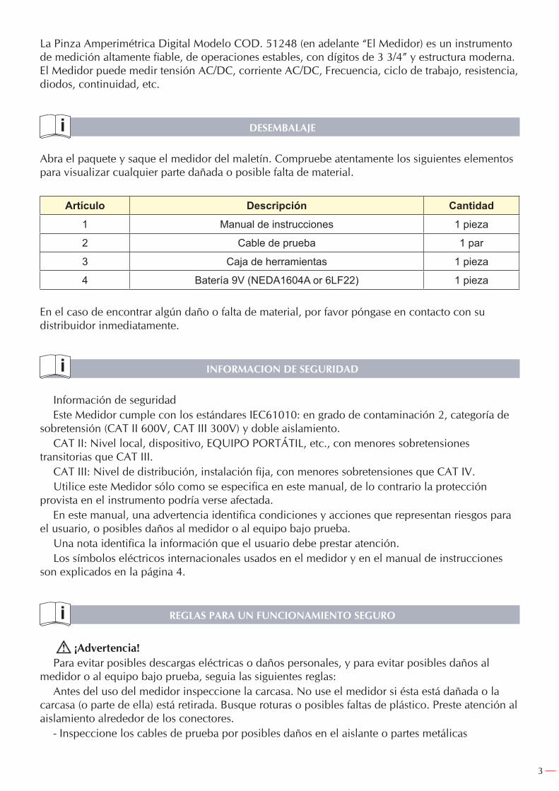
La Pinza Amperimétrica Digital Modelo COD. 51248 (en adelante “El Medidor) es un instrumento de medición altamente fiable, de operaciones estables, con dígitos de 3 3/4” y estructura moderna. El Medidor puede medir tensión AC/DC, corriente AC/DC, Frecuencia, ciclo de trabajo, resistencia, diodos, continuidad, etc.
DESEMBALAJE
Abra el paquete y saque el medidor del maletín. Compruebe atentamente los siguientes elementos para visualizar cualquier parte dañada o posible falta de material.
Artículo Descripción Cantidad1 Manual de instrucciones 1 pieza
2 Cable de prueba 1 par
3 Caja de herramientas 1 pieza
4 Batería 9V (NEDA1604A or 6LF22) 1 pieza
En el caso de encontrar algún daño o falta de material, por favor póngase en contacto con su distribuidor inmediatamente.
INFORMACION DE SEGURIDAD
Información de seguridadEste Medidor cumple con los estándares IEC61010: en grado de contaminación 2, categoría de
sobretensión (CAT II 600V, CAT III 300V) y doble aislamiento.CAT II: Nivel local, dispositivo, EQUIPO PORTÁTIL, etc., con menores sobretensiones
transitorias que CAT III.CAT III: Nivel de distribución, instalación fija, con menores sobretensiones que CAT IV.Utilice este Medidor sólo como se especifica en este manual, de lo contrario la protección
provista en el instrumento podría verse afectada.En este manual, una advertencia identifica condiciones y acciones que representan riesgos para
el usuario, o posibles daños al medidor o al equipo bajo prueba.Una nota identifica la información que el usuario debe prestar atención.Los símbolos eléctricos internacionales usados en el medidor y en el manual de instrucciones
son explicados en la página 4.
REGLAS PARA UN FUNCIONAMIENTO SEGURO
¡Advertencia!Para evitar posibles descargas eléctricas o daños personales, y para evitar posibles daños al
medidor o al equipo bajo prueba, seguia las siguientes reglas:Antes del uso del medidor inspeccione la carcasa. No use el medidor si ésta está dañada o la
carcasa (o parte de ella) está retirada. Busque roturas o posibles faltas de plástico. Preste atención al aislamiento alrededor de los conectores.
- Inspeccione los cables de prueba por posibles daños en el aislante o partes metálicas
4
expuestas. Verifique la continuidad de los cables de prueba. Reemplace los cables dañados por unos de idéntico número de modelo o especificaciones eléctricas antes del uso del medidor.
- No aplique más del ratio de tensión marcado en el medidor, entre los terminales o entre cualquier terminal y la toma de tierra. Si el valor a ser medido es desconocido, use la posición de máximo rango y redúzcalo poco a poco hasta que la lectura obtenida sea satisfactoria.
- Cuando la medición haya sido completada, desconecte la conexión entre los cables de prueba y el circuito bajo prueba, retire los cables de prueba de la entrada de los terminales del medidor y apague el medidor.
- La posición del selector debería estar situado en la posición correcta y sin ningún cambio durante la medición evitando daños en el Medidor.
- No lleve a cabo la mediciones cuando la carcasa trasera del Medidor y el compartimento de la batería no estén cerrados correctamente para evitar descargas eléctricas.
- No introduzca tensiones superiores a 1000V en DC o 750V en AC entre los terminales de entrada del medidor, para evitar descargas eléctricas y daños al Medidor.
- Cuando el Medidor trabaje con una tensión eficaz por encima de 70V en DC o 33V rms en AC, se deberá tomar especial cuidado al peligro de posibles descargas eléctricas.
- No utilice o almacene el Medidor en un ambiente de alta temperatura, humedad, explosivo, inflamable y fuertes campos magnéticos. La capacidad del Medidor puede deteriorarse después de humedecerse.
- Cuando utilice los cables de prueba, mantenga sus dedos tras el protector.- Para evitar descargas eléctricas, no toque los cables desnudos, conectores, entradas del
terminal sin uso o el circuito bajo prueba durante la medición.- Desconecte la energía del circuito y descargue todos los condensadores de alta tensión antes
de testear la resistencia, continuidad y diodo.- Reemplace la batería tan pronto como el indicador de batería aparezca. Con una batería baja,
el Medidor puede producir falsas lecturas que pueden conducir a descargas eléctricas o daños personales.
- Al reparar el Medidor, use solamente repuestos del mismo número de modelo o repuestos de idénticas especificaciones eléctricas.
- El circuito interno del Medidor no debe ser alterado para evitar posibles daños al Medidor y cualquier accidente.
- La superficie del Medidor debe ser limpiada con un trapo suave y un detergente suave. No deben usarse disolventes ni abrasivos para prevenir la corrosión de la superficie, daño o accidente.
- El Medidor el apropiado para uso en interior.- Apague el medidor cuando no esté en uso y extraiga la batería cuando no sea usada durante un
largo periodo de tiempo.- Compruebe constantemente la batería ya que puede tener pérdidas cuando haya sido usado
durante algún tiempo, remplace la batería tan pronto como las pérdidas aparezcan.
SIMBOLOS ELECTRICOS INTERNACIONALES
Doble aislante
Toma de Tierra
Advertencia. Consultar manual de instrucciones.
AC (Corriente Alterna)
5
DC (Corriente Contínua)
Prueba de continuidad
Diodo
Deficiencia de la batería
AC o DC
Peligro de Alto Voltaje
Conforme con los estándares de la Unión Europea
ESTRUCTURA DEL MEDIDOR (vea figura 1)
1. Protector de manos: Para proteger las manos del usuario de tocar áreas peligrosas.2. Gatillo: Presione para abrir la pinza. Cuando la presión sobre el gatillo se libera, la pinza se
cierra.3. Botones funcionales4. Terminales de entrada5. Pantalla LCD6. Ruleta7. Pinza: diseñado para tomar la corriente AC y DC que fluyente por el conductor. El
conductor de prueba debe pasar verticalmente por el centro de la pinza.
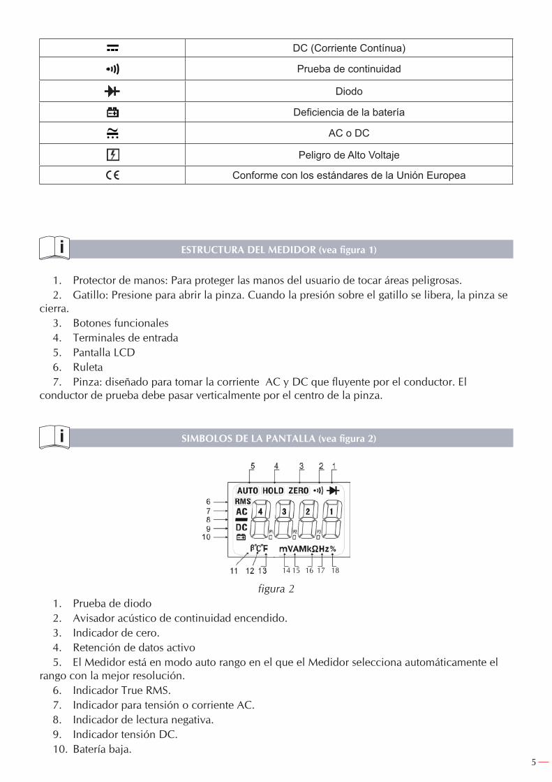
SIMBOLOS DE LA PANTALLA (vea figura 2)
14 15 16 17 18
figura 21. Prueba de diodo2. Avisador acústico de continuidad encendido.3. Indicador de cero.4. Retención de datos activo5. El Medidor está en modo auto rango en el que el Medidor selecciona automáticamente el
rango con la mejor resolución.6. Indicador True RMS.7. Indicador para tensión o corriente AC.8. Indicador de lectura negativa.9. Indicador tensión DC.10. Batería baja.
6
Advertencia: Para evitar falsas lecturas, que puedan conducir a posibles descargas eléctricas o daños personales, reemplace la batería tan pronto como el indicador de batería aparezca.
11. Unidad del transistor hEF.12. Unidad de temperatura, ºC: Centígrados, ºF: Fahrenheit.13. Unidad de temperatura, ºC: Centígrados, ºF: Fahrenheit.14. Voltios. Unidad de tensión. mV: Milivoltios.15. Amperios (amps). Unidad de corriente.16. Unidad de resistencia (Ohmios, k:Kilohmios, M: Megaohmios)17. Unidad de frecuencia. (HZ: Hercios, KHz: Kilohercios, MHz: Megahercios)18. Medida ciclo de trabajo.
FUNCION DE LOS BOTONES
La siguiente tabla aporta información sobre las funciones de los botones.Botón Operación desempeñada
SELECT Presione botón SELECT para seleccionar las funciones alternativas como V , y .
RANGECaracterísticas del rango:
AUTO Exit y entrada a escala MANUAL. En MANUAL, selecciona el siguiente rango de entrada. EXIT para retornar a AUTO. AUTO por defecto.
Presione una vez para encender la retroiluminación de la pantalla. Presione nuevamente para apagar la retroiluminación de la pantalla, de otro modo se
apagará automáticamente transcurridos 15 segundos..
HOLD
Presione HOLD para entrar en modo retención en cualquier modo (excepto %Hz), el Medidor sonará.
-Presione HOLD de nuevo para salir del modo retención para volver al modo medición, el Medidor sonará.
-Girando la ruleta o presionando cualquier botón se puede también salir del modo retención.
Hz% Cuando el Medidor esté en %Hz, V y A , presione %Hz para medir la frecuencia y ciclo de trabajo
ZERO Presione ZERO para resetear la pantalla antes de la medición de tensión AC/DC, corriente AC/DC , resistencia y capacitancia.
APAGADO AUTOMATICO
Si durante 15 minutos no se produce un cambio en la posición del selector giratorio o no es presionado ningún botón, la pantalla se pondrá en blanco y el medidor entrará en modo “sleep”. Mientras esté modo “sleep”, presionando cualquier botón funcional o girando la ruleta el Medidor podrá encenderse. Para deshabilitar el modo “sleep”, presione SELECT mientras enciende el Medidor.
7
LA EFECTIVIDAD DE LOS BOTONES
No todos los botones funcionales pueden ser usados en cualquier posición del selector giratorio. La tabla de a continuación describe las funciones de los botones que pueden ser usadoa con las diferentes posiciones del selector giratorio.
Posición del selector
Función de los botones
SELECCION RANGO HOLD %Hz ZERO
V ● ● ● ● ● ●
● N/A ● ● N/A ●Ω N/A ● ● ● N/A ●
%Hz N/A N/A ● N/A ● N/A
40A ● N/A ● ● ● ●
400A ● N/A ● ● ● ●
1000A ● N/A ● ● ● ●ºC N/A N/A ● ● N/A N/A
OPERACION DE MEDIDA
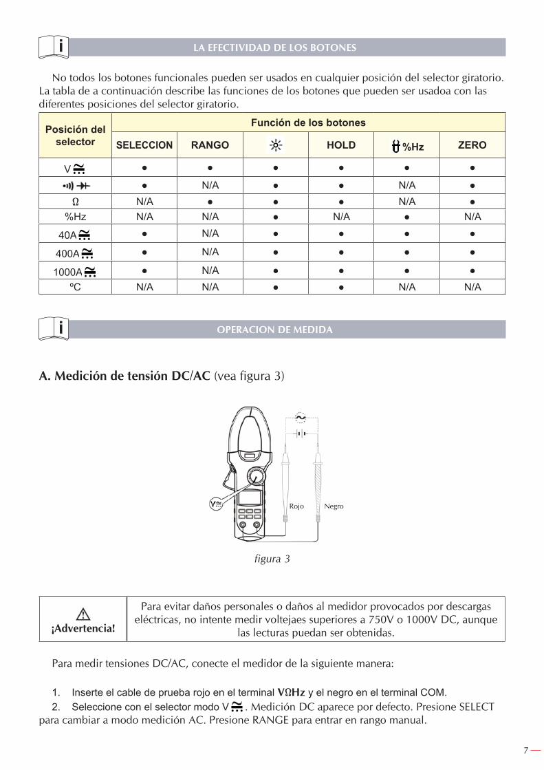
A. Medición de tensión DC/AC (vea figura 3)
figura 3
¡Advertencia!
Para evitar daños personales o daños al medidor provocados por descargas eléctricas, no intente medir voltejaes superiores a 750V o 1000V DC, aunque
las lecturas puedan ser obtenidas.
Para medir tensiones DC/AC, conecte el medidor de la siguiente manera:
1. Inserte el cable de prueba rojo en el terminal VΩHz y el negro en el terminal COM.2. Seleccione con el selector modo V . Medición DC aparece por defecto. Presione SELECT
para cambiar a modo medición AC. Presione RANGE para entrar en rango manual.
Rojo Negro
8
3. Presione botón %Hz para medir frecuencia o ciclo de trabajo, pero las lecturas de frecuencia o ciclos de trabajo obtenidos de este rango son sólo para referencia.
4. Conecte los cables de prueba con el objeto a medir. El valor de la medición se verá reflejado en la pantalla.
Nota:-AC Milivolt es un modo de medida de rango manual.-En cada rango el Medidor tiene una impedancia de entrada de 10M. Este efecto de carga puede
causar errores de medición en circuitos de alta impedancia. Si la impedancia del circuito es menor o igual que 10k, el error es despreciable (0,1% o menos).
- Cuando la medición de tensión DC/AC haya sido completado, desconecte la conexión entre los cables de prueba y el circuito bajo prueba y retire los cables de prueba de las entradas del terminal.
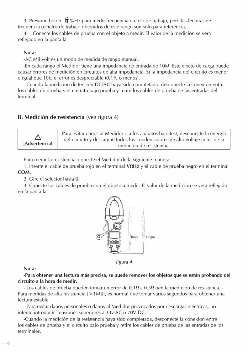
B. Medición de resistencia (vea figura 4)
¡Advertencia!
Para evitar daños al Medidor o a los aparatos bajo test, desconecte la energía del circuito y descargue todos los condensadores de alto voltaje antes de la
medición de resistencia.
Para medir la resistencia, conecte el Medidor de la siguiente manera:1. Inserte el cable de prueba rojo en el terminal VΩHz y el cable de prueba negro en el terminal
COM.2. Gire el selector hasta Ω.3. Conecte los cables de prueba con el objeto a medir. El valor de la medición se verá reflejado
en la pantalla.
figura 4Nota:-Para obtener una lectura más precisa, se puede remover los objetos que se están probando del
circuito a la hora de medir.- Los cables de prueba pueden tomar un error de 0.1Ω a 0.3Ω oen la medición de resistenca. -
Para medidas de alta resistencia (>1MΩ), es normal que tomar varios segundos para obtener una lectura estable.
- Para evitar daños personales o daños al Medidor provocados por descargas eléctricas, no intente introducir tensiones superiores a 33v AC o 70V DC.
-Cuando la medición de la resistencia haya sido completada, desconecte la conexión entre los cables de prueba y el circuito bajo prueba y retire los cables de prueba de las entradas de los terminales.
Rojo Negro
9
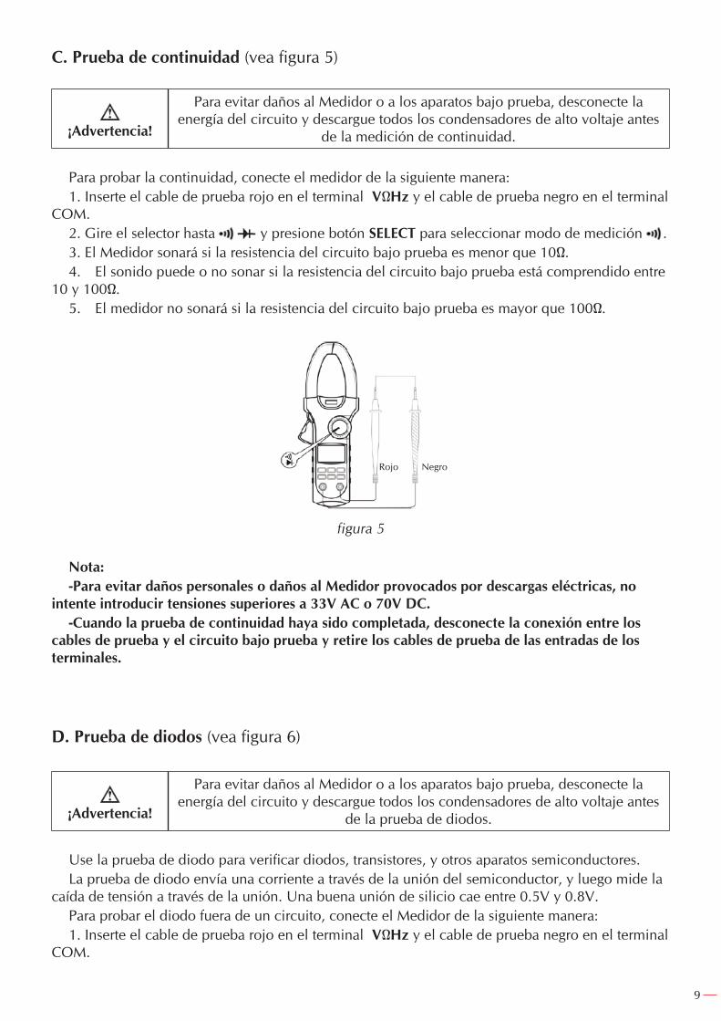
C. Prueba de continuidad (vea figura 5)
¡Advertencia!
Para evitar daños al Medidor o a los aparatos bajo prueba, desconecte la energía del circuito y descargue todos los condensadores de alto voltaje antes
de la medición de continuidad.
Para probar la continuidad, conecte el medidor de la siguiente manera:1. Inserte el cable de prueba rojo en el terminal VΩHz y el cable de prueba negro en el terminal
COM.2. Gire el selector hasta y presione botón SELECT para seleccionar modo de medición .3. El Medidor sonará si la resistencia del circuito bajo prueba es menor que 10Ω.4. El sonido puede o no sonar si la resistencia del circuito bajo prueba está comprendido entre
10 y 100Ω.5. El medidor no sonará si la resistencia del circuito bajo prueba es mayor que 100Ω.
figura 5
Nota:-Para evitar daños personales o daños al Medidor provocados por descargas eléctricas, no
intente introducir tensiones superiores a 33V AC o 70V DC.-Cuando la prueba de continuidad haya sido completada, desconecte la conexión entre los
cables de prueba y el circuito bajo prueba y retire los cables de prueba de las entradas de los terminales.
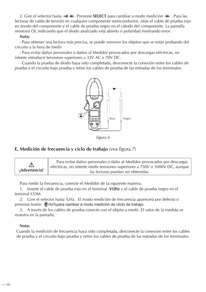
D. Prueba de diodos (vea figura 6)
¡Advertencia!
Para evitar daños al Medidor o a los aparatos bajo prueba, desconecte la energía del circuito y descargue todos los condensadores de alto voltaje antes
de la prueba de diodos.
Use la prueba de diodo para verificar diodos, transistores, y otros aparatos semiconductores.La prueba de diodo envía una corriente a través de la unión del semiconductor, y luego mide la
caída de tensión a través de la unión. Una buena unión de silicio cae entre 0.5V y 0.8V.Para probar el diodo fuera de un circuito, conecte el Medidor de la siguiente manera:1. Inserte el cable de prueba rojo en el terminal VΩHz y el cable de prueba negro en el terminal
COM.
Rojo Negro
10
2. Gire el selector hasta . Presione SELECT para cambiar a modo medición . Para las lecturas de caída de tensión en cualquier componente semiconductor, sitúe el cable de prueba rojo en ánodo del componente y el cable de prueba negro en el cátodo del componente. La pantalla mostrará OL indicando que el diodo analizado está abierto o polaridad mostrando error.
Nota:- Para obtener una lectura más precisa, se puede remover los objetos que se están probando del
circuito a la hora de medir- Para evitar daños personales o daños al Medidor provocados por descargas eléctricas, no
intente introducir tensiones superiores a 33V AC o 70V DC.- Cuando la prueba de diodo haya sido completada, desconecte la conexión entre los cables de
prueba y el circuito bajo prueba y retire los cables de prueba de las entradas de los terminales.
figura 6
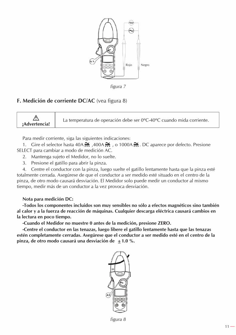
E. Medición de frecuencia y ciclo de trabajo (vea figura 7)
¡Advertencia!
Para evitar daños personales o daño al Medidor provocados por descargas eléctricas, no intente medir tensiones superiores a 750V o 1000V DC, aunque
las lecturas puedan ser obtenidas.
Para medir la frecuencia, conecte el Medidor de la siguiente manera:1. Inserte el cable de prueba rojo en el terminal VΩHz y el cable de prueba negro en el
terminal COM.2. Gire el selector hasta %Hz. El modo medición de frecuencia aparecerá por defecto o
presione botón Hz%para cambiar a modo medición de cliclo de trabajo.3. A través de los cables de prueba conecte con el objeto a medir. El valor de la medida se
muestra en la pantalla.
Nota:Cuando la medición de frecuencia haya sido completada, desconecte la conexión entre los cables de prueba y el circuito bajo prueba y retire los cables de prueba de las entradas de los terminales.
Rojo Negro
11
figura 7
F. Medición de corriente DC/AC (vea figura 8)
¡Advertencia!La temperatura de operación debe ser 0ºC-40ºC cuando mida corriente.
Para medir corriente, siga las siguientes indicaciones:1. Gire el selector hasta 40A ,400A , o 1000A . DC aparece por defecto. Presione
SELECT para cambiar a modo de medición AC.2. Mantenga sujeto el Medidor, no lo suelte.3. Presione el gatillo para abrir la pinza.4. Centre el conductor con la pinza, luego suelte el gatillo lentamente hasta que la pinza esté
totalmente cerrada. Asegúrese de que el conductor a ser medido esté situado en el centro de la pinza, de otro modo causará desviación. El Medidor solo puede medir un conductor al mismo tiempo, medir más de un conductor a la vez provoca desviación.
Nota para medición DC:-Todos los componentes incluidos son muy sensibles no sólo a efectos magnéticos sino también
al calor y a la fuerza de reacción de máquinas. Cualquier descarga eléctrica causará cambios en la lectura en poco tiempo.
-Cuando el Medidor no muestre 0 antes de la medición, presione ZERO.-Centre el conductor en las tenazas, luego libere el gatillo lentamente hasta que las tenazas
estén completamente cerradas. Asegúrese que el conductor a ser medido esté en el centro de la pinza, de otro modo causará una desviación de ±1.0 %.
figura 8
Rojo Negro
12
Para obtener mayor precisión en corriente DC puede seguir el siguiente método:-Apague la corriente del conductor medido.-Presione el gatillo para abrir la pinza.Cuando la lectura esté establecida al mínimo, pulse ZERO para mostrar cero.-Encienda la corriente del conductor a medir, lea la lectura después de que el Medidor esté
estable.
Nota para medida de AC.-Centre el conductor en la pinza, luego libere el gatillo lentamente hasta que la pinza esté
completamente cerrada, de otro modo causará una desviación de ±1.0 %.-El medidor se pondrá a cero automáticamente.- Cuando la medición de corriente >1A, presione botón Hz. Presione botón Hz para alternar
entre corriente AC y modo de medición de frecuencia. Las lecturas de frecuencia obtenidas desde este rango son sólo para referencia.
- Par AC y método de respuesta True RMS. Entrada de onda sinusoidal para ajustar. La onda sinusoidal no debe seguir los siguientes datos para ajustar:
Factor pico: 1.4-2.0, añadir 1.0% en la precisión indicada.Factor pico: 2.0-2.5, añadir 2.5% en la precisión indicada.Factor pico: 2.5-3.0, añadir 4.0% en la precisión indicada.
ESPECIFICACIONES
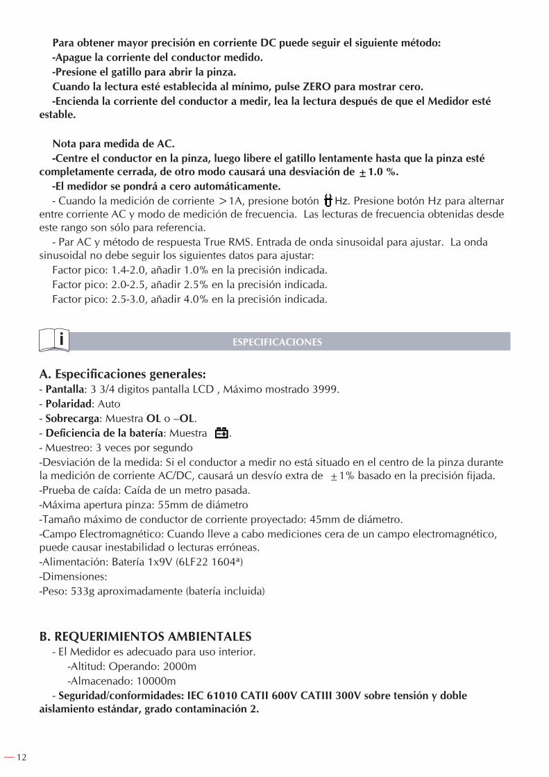
A. Especificaciones generales:- Pantalla: 3 3/4 digitos pantalla LCD , Máximo mostrado 3999.- Polaridad: Auto- Sobrecarga: Muestra OL o –OL.- Deficiencia de la batería: Muestra .- Muestreo: 3 veces por segundo-Desviación de la medida: Si el conductor a medir no está situado en el centro de la pinza durante la medición de corriente AC/DC, causará un desvío extra de ±1% basado en la precisión fijada.-Prueba de caída: Caída de un metro pasada.-Máxima apertura pinza: 55mm de diámetro-Tamaño máximo de conductor de corriente proyectado: 45mm de diámetro.-Campo Electromagnético: Cuando lleve a cabo mediciones cera de un campo electromagnético, puede causar inestabilidad o lecturas erróneas.-Alimentación: Batería 1x9V (6LF22 1604ª)-Dimensiones: -Peso: 533g aproximadamente (batería incluida)
B. REQUERIMIENTOS AMBIENTALES- El Medidor es adecuado para uso interior. -Altitud: Operando: 2000m -Almacenado: 10000m- Seguridad/conformidades: IEC 61010 CATII 600V CATIII 300V sobre tensión y doble
aislamiento estándar, grado contaminación 2.
13
- Temperatura y humedad: Operando: 0ºC~30ºC(≤85%R.H) 30ºC~40ºC (≤75%R.H) 40ºC~50ºC(≤45%R.H) Almacenado: -20ºC~+60ºC (≤85%R.H)
ESPECIFICACIONES DE PRECISION
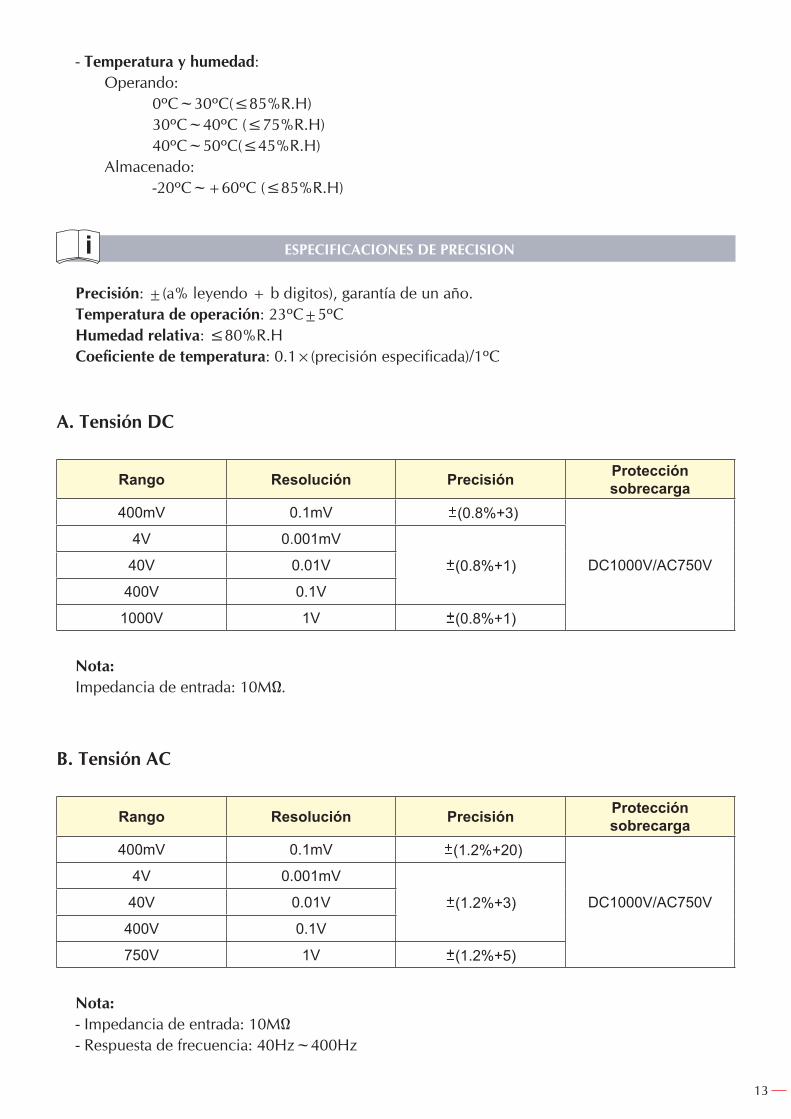
Precisión: ±(a% leyendo + b digitos), garantía de un año.Temperatura de operación: 23ºC±5ºCHumedad relativa: ≤80%R.HCoeficiente de temperatura: 0.1×(precisión especificada)/1ºC
A. Tensión DC
Rango Resolución Precisión Protección sobrecarga
400mV 0.1mV (0.8%+3)
DC1000V/AC750V
4V 0.001mV
(0.8%+1)40V 0.01V
400V 0.1V
1000V 1V (0.8%+1)
Nota: Impedancia de entrada: 10MΩ.
B. Tensión AC
Rango Resolución Precisión Protección sobrecarga
400mV 0.1mV (1.2%+20)
DC1000V/AC750V
4V 0.001mV
(1.2%+3)40V 0.01V
400V 0.1V
750V 1V (1.2%+5)
Nota:- Impedancia de entrada: 10MΩ- Respuesta de frecuencia: 40Hz~400Hz
14
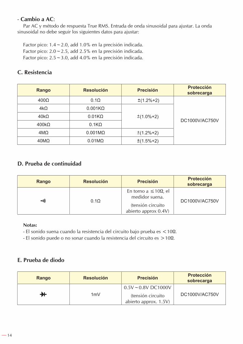
- Cambio a AC:Par AC y método de respuesta True RMS. Entrada de onda sinusoidal para ajustar. La onda
sinusoidal no debe seguir los siguientes datos para ajustar:
Factor pico: 1.4~2.0, add 1.0% en la precisión indicada.Factor pico: 2.0~2.5, add 2.5% en la precisión indicada.Factor pico: 2.5~3.0, add 4.0% en la precisión indicada.
C. Resistencia
Rango Resolución Precisión Protección sobrecarga
400Ω 0.1Ω (1.2%+2)
DC1000V/AC750V
4kΩ 0.001KΩ
(1.0%+2)40kΩ 0.01KΩ
400kΩ 0.1KΩ
4MΩ 0.001MΩ (1.2%+2)
40MΩ 0.01MΩ (1.5%+2)
D. Prueba de continuidad
Rango Resolución Precisión Protección sobrecarga
0.1Ω
En torno a ≤10Ω, el medidor suena.
(tensión circuito abierto approx 0.4V)
DC1000V/AC750V
Notas:- El sonido suena cuando la resistencia del circuito bajo prueba es <10Ω.- El sonido puede o no sonar cuando la resistencia del circuito es >10Ω.
E. Prueba de diodo
Rango Resolución Precisión Protección sobrecarga
1mV0.5V~0.8V DC1000V
(tensión circuito abierto approx. 1.5V)
DC1000V/AC750V
15
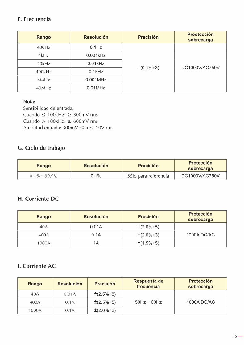
F. Frecuencia
Rango Resolución Precisión Preotección sobrecarga
400Hz 0.1Hz
(0.1%+3) DC1000V/AC750V
4kHz 0.001kHz
40kHz 0.01kHz
400kHz 0.1kHz
4MHz 0.001MHz
40MHz 0.01MHz
Nota:Sensibilidad de entrada:Cuando ≤ 100kHz: ≥ 300mV rmsCuando > 100kHz: ≥ 600mV rmsAmplitud entrada: 300mV ≤ a ≤ 10V rms
G. Ciclo de trabajo
Rango Resolución Precisión Protección sobrecarga
0.1%~99.9% 0.1% Sólo para referencia DC1000V/AC750V
H. Corriente DC
Rango Resolución Precisión Protección sobrecarga
40A 0.01A (2.0%+5)
1000A DC/AC400A 0.1A (2.0%+3)
1000A 1A (1.5%+5)
I. Corriente AC
Rango Resolución Precisión Respuesta de frecuencia
Protección sobrecarga
40A 0.01A (2.5%+8)
50Hz ~ 60Hz 1000A DC/AC400A 0.1A (2.5%+5)
1000A 0.1A (2.0%+2)
16
MANTENIMIENTO
Esta sección proporciona información básica de mantenimiento incluyendo instrucciones de sustitución de la batería.
¡Advertencia!
No intente reparar o dar servicio a su Medidor a menos que usted esté cualificado para hacerlo y tener la calibración correspondiente y servicios de
información.
Para evitar descargas eléctricas o daños al medidor, no introduzca agua en el interior del aparato.
A. Servicio General-Periódicamente limpie la carcasa con un paño suave y detergente suave. No utilice abrasivos o
disolventes.-Limpiar el terminal con una barra de algodón y detergente, cuando la suciedad en el terminal
pueda afectar a las lecturas.-Apague el Medidor cuando no vaya a ser usado.-Retire la batería cuando ésta no vaya a ser usada durante un largo periodo de tiempo.-No utilice o almacene el Medidor en lugares húmedos, de alta temperatura, explosivos,
inflamables y fuertes campos magnéticos.
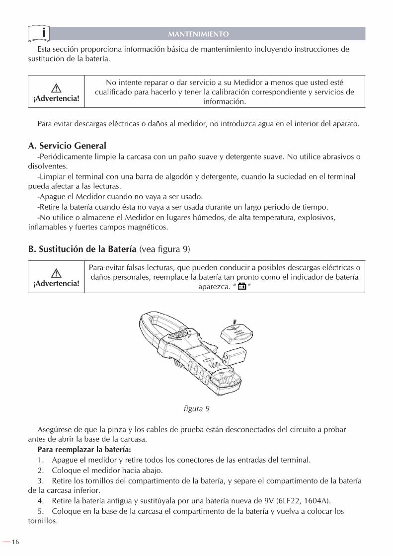
B. Sustitución de la Batería (vea figura 9)
¡Advertencia!
Para evitar falsas lecturas, que pueden conducir a posibles descargas eléctricas o daños personales, reemplace la batería tan pronto como el indicador de batería
aparezca. “ ”
figura 9
Asegúrese de que la pinza y los cables de prueba están desconectados del circuito a probar antes de abrir la base de la carcasa.
Para reemplazar la batería:1. Apague el medidor y retire todos los conectores de las entradas del terminal.2. Coloque el medidor hacia abajo.3. Retire los tornillos del compartimento de la batería, y separe el compartimento de la batería
de la carcasa inferior.4. Retire la batería antigua y sustitúyala por una batería nueva de 9V (6LF22, 1604A).5. Coloque en la base de la carcasa el compartimento de la batería y vuelva a colocar los
tornillos.
17
NOTAS
IMPORTANTE!
El fabricante no se responsabiliza de los daños o mal funcionamiento del aparato, en caso de que no se use correctamente o se haya utilizado para trabajos para los que no esté diseñado.
De acuerdo con la Directiva de Residuos de Aparatos Eléctricos y Electrónicos (RAEE), estos deben ser recogidos y dispuestos por separado. Si usted tiene que tirar, por favor, no use la basura habitual. Por favor, póngase en contacto con su distribuidor para el reciclaje de forma gratuita.
GARANTIA
Esta garantía no cubre aquellas piezas que por su uso normal tienen un desgaste.
Nota: para obtener la validez de la garantía, es absolutamente imprescindible que complete y remita al fabricante el documento de “CERTIFICADO DE GARANTIA”, dentro de los siete dias a partir de la fecha de compra.
18
TABLE OF CONTENTS
Overview .................................................................................................................. 18Unpacking Inspection ...................................................................................................... 19Safety Information ........................................................................................................... 19Rules for Safe Operation .................................................................................................. 19International Electrical Symbols ....................................................................................... 20The Meter Structure ......................................................................................................... 21Display Symbols .............................................................................................................. 21Functional Buttons ........................................................................................................... 22The Effectiveness of Functional Buttons ........................................................................... 22Measurement Operation .................................................................................................. 22 A. DC/AC Voltage Measurement ................................................................................ 24 B. Measuring Resistance ............................................................................................. 25 C. Testing for Continuity ............................................................................................. 25 D. Testing Diodes ....................................................................................................... 26 E. Frequency and Duty Cycle Measurement ................................................................ 27 F. DC/AC Current Measurement ................................................................................. 27Specifications .................................................................................................................. 28 A. General Specifications ............................................................................................ 28 B. Environmental Requirements .................................................................................. 28Accuracy Specifications ................................................................................................... 29Maintenance .................................................................................................................. 32 A. General Service ...................................................................................................... 32 B. Replacing the Battery.............................................................................................. 32
OVERVIEW
This Operating Manual covers information on safety and cautions. Please read the relevant information carefully and observe all the Warnings and Notes strictly.
Warning!To avoid electric shock or personal injury, read the “Safety Information” and
“Rules for Safe Operation” carefully before using the Meter.
ENGLISH
19
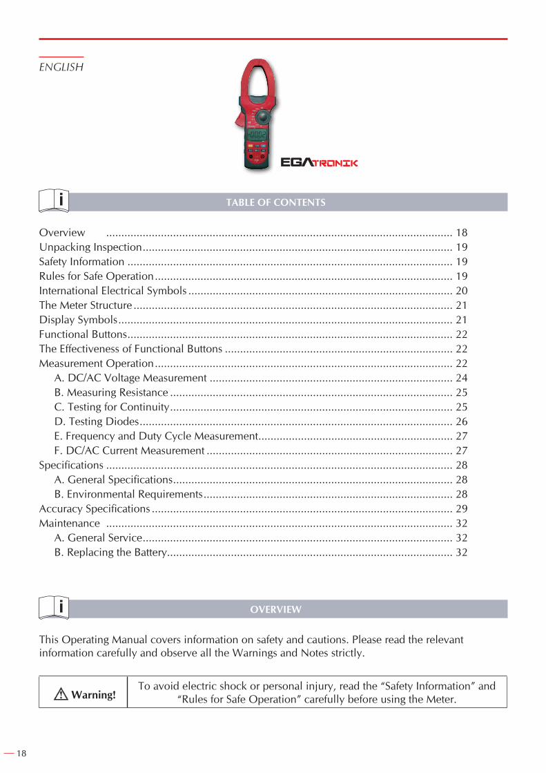
Digital Clamp Multimeter Model COD. 51248 (hereafter referred to as “the Meter”) is 3 3/4 digits with steady operations, fashionable structure and highly reliable measuring instrument. The Meter uses large scale of integrated circuit with double integrated A/D converter as its core and has full range overload protection.The Meter can measure AC/DC Voltage, AC/DC Current, Frequency, Duty Cycle, Resistance, Diodes, Continuity and etc.
UNPACKING INSPECTION
Open the package case and take out the Meter. Check the following items carefully to see any missing or damaged part:
Item Description Qty1 Operating Manual 1 piece
2 Test Lead 1 pair
3 Tool box 1 piece
4 9V Battery (NEDA1604A or 6LF22) 1 piece
In the event you find any missing or damage, please contact your dealer immediately.
SAFETY INFORMATION
This Meter complies with the standards IEC61010: in pollution degree 2, overvoltage category (CAT II 600V, CAT III 300V) and double insulation.
CAT II: Local level, appliance, PORTABLE EQUIPMENT etc., with smaller transient overvoltages than CAT III.
CAT III: Distribution level, fixed installation, with smaller transient overvoltages than CAT IV.Use the Meter only as specified in this operating manual, otherwise the protection provided by
the Meter may be impaired.In this manual, a Warning identifies conditions and actions that pose hazards to the user, or may
damage the Meter or the equipment under test.A Note identifies the information that user should pay attention to.International electrical symbols used on the Meter and in this Operating Manual are explained
on page 20.
RULES FOR SAFE OPERATION
Warning!To avoid possible electric shock or personal injury, and to avoid possible damage
to the Meter or to the equipment under test, adhere to the following rules:
Before using the Meter inspect the case. Do not use the Meter if it is damaged or the case (or part of the case) is removed. Look for cracks or missing plastic. Pay attention to the insulation around the connectors.
- Inspect the test leads for damaged insulation or exposed metal. Check the test leads for continuity. Replace damaged test leads with identical model number or electrical specifications before using the Meter.
20
- Do not apply more that the rated voltage, as marked on the Meter, between the terminals or between any terminal and grounding. If the value to be measured is unknown, use the maximum measurement position and reduce the range step by step until a satisfactory reading is obtained.
- When measurement has been completed, disconnect the connection between the test leads and the circuit under test, remove the testing leads away from the input terminals of the Meter and turn the Meter power off.
- The rotary switch should be placed in the right position and no any changeover of range shall be made during measurement is conducted to prevent damage of the Meter.
- Do not carry out the measurement when the Meter’s back case and battery compartment are not closed to avoid electric shock.
- Do not input higher than 1000V in DC or 750 V in AC between the two Meter’s input terminal to avoid electric shock and damages to the Meter.
- When the Meter working at an effective voltage over 70V in DC or 33V rms in AC, special care should be taken for there is danger of electric shock.
- Use the proper terminals, function, and range for your measurements.- Do not use or store the Meter in an environment of high temperature, humidity, explosive,
inflammable and strong magnetic field. The performance of the Meter may deteriorate after dampened.
- When using the test leads, keep your fingers behind the finger guards.- To avoid electric shock, do not touch the bare wires, connectors, unused input terminals or the
circuit under testing during measurement.- Disconnect circuit power and discharge all high-voltage capacitors before testing resistance,
continuity and diode.- Replace the battery as soon as the battery indicator appears. With a low battery, the Meter
might produce false readings that can lead to electric shock and personal injury.- When servicing the Meter, use only the same model number or identical electrical
specifications replacement parts.- The internal circuit of the Meter shall not be altered at will to avoid damage of the Meter and
any accident.- Soft cloth and mild detergent should be used to clean the surface of the Meter when servicing.
No abrasive and solvent should be used to prevent the surface of the Meter from corrosion, damage and accident.
- The Meter is suitable for indoor use.- Turn the Meter off when it is not in use and take out the battery when not using for a long time.- Constantly check the battery as it may leak when it has been using for some time, replace the
battery as soon as leaking appears. A leaking battery will damage the Meter.
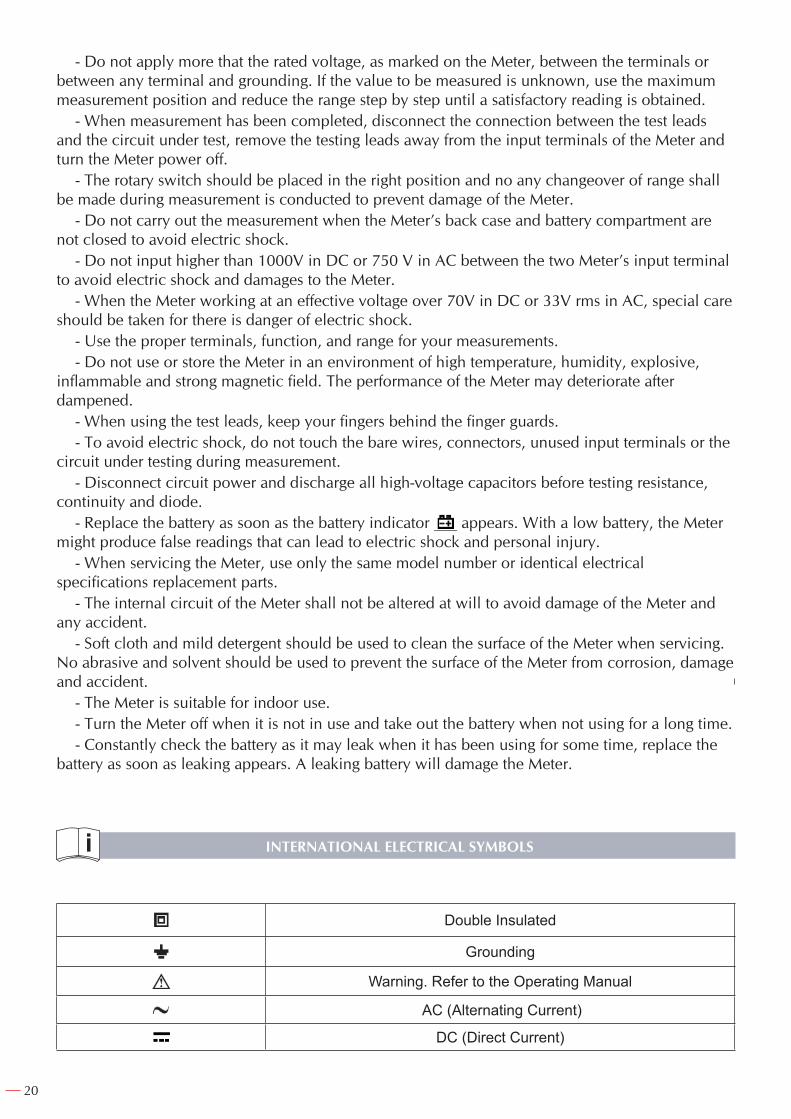
INTERNATIONAL ELECTRICAL SYMBOLS
Double Insulated
Grounding
Warning. Refer to the Operating Manual
AC (Alternating Current)
DC (Direct Current)
21
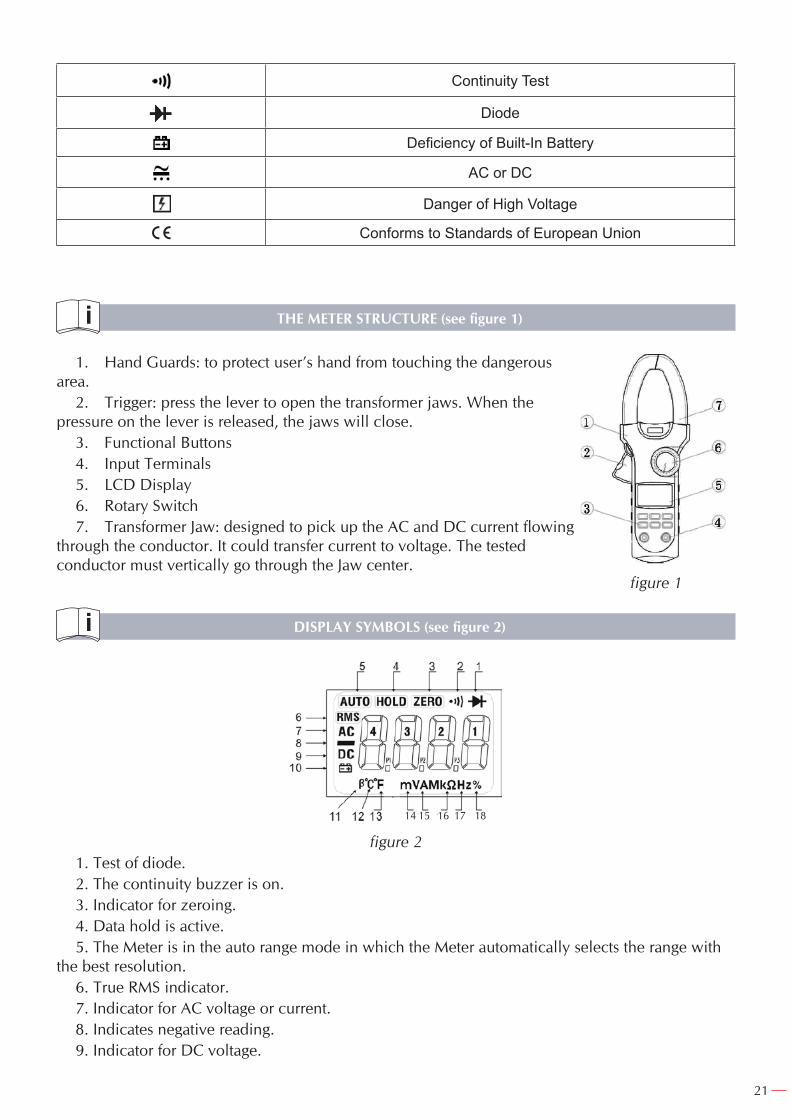
Continuity Test
Diode
Deficiency of Built-In Battery
AC or DC
Danger of High Voltage
Conforms to Standards of European Union
THE METER STRUCTURE (see figure 1)
1. Hand Guards: to protect user’s hand from touching the dangerous area.
2. Trigger: press the lever to open the transformer jaws. When the pressure on the lever is released, the jaws will close.
3. Functional Buttons4. Input Terminals5. LCD Display6. Rotary Switch7. Transformer Jaw: designed to pick up the AC and DC current flowing
through the conductor. It could transfer current to voltage. The tested conductor must vertically go through the Jaw center.
DISPLAY SYMBOLS (see figure 2)
14 15 16 17 18
figure 21. Test of diode.2. The continuity buzzer is on.3. Indicator for zeroing.4. Data hold is active.5. The Meter is in the auto range mode in which the Meter automatically selects the range with
the best resolution.6. True RMS indicator.7. Indicator for AC voltage or current.8. Indicates negative reading.9. Indicator for DC voltage.
figure 1
22
10. The battery is low.Warning: To avoid false readings, which could lead to possible electric shock or personal injury,
replace the battery as soon as the battery indicator appears.11. The unit of transistor hEF.12. The unit of temperature, ºC: Centigrade temperature.13. The unit of temperature, ºF: Fahrenheit temperature.14. Volts. The unit of voltage. mV: Millivolt.15. Amperes (amps). The unit of current.16. The unit of resistance. (Ω: Ohm, kΩ:Kilohm, MΩ:Megohm )17. The unit of frequency. (Hz: Hertz, KHz: Kilohertz, MHz: Meghertz)18. Duty cycle measurement.
FUNCTIONAL BUTTONS
Below table indicated for information about the functional button operations.
Button Operation PerformedSELECT Press SELECT button to select the alternate functions including V , and .
RANGERange feature:
Exit AUTO and enter MANUAL ranging. In MANUAL, select next input range. EXIT to return to AUTO. AUTO is default.
Press once to turn the display backlight on. Press again to turn the display backlight off, otherwise it will automatically off after 15 seconds.
HOLD
- Press HOLD to enter the Hold mode in any mode (except %Hz), the Meter beeps.- Press HOLD again to exit the Hold mode to return to measurement mode, the
Meter beeps.- Turn the rotary switch or press any button can also exit hold mode.
Hz% When the Meter is at %Hz, V and A , press %Hz to measure frequency and duty cycle.
ZERO Press ZERO to zeroing the display before measuring AC/DC voltage, AC/DC current, resistance and capacitance.
AUTOMATIC POWER OFF
The display blanks and the Meter goes into a “sleep” mode if you have not changed the rotary switch position or pressed a button for 15 minutes. While in Sleep mode, pressing the any effective Functional button or turning the rotary switch could turn the Meter on. To disable the sleep mode function, press SELECT button while turning on the meter.
THE EFFECTIVENESS OF FUNCTIONAL BUTTONS
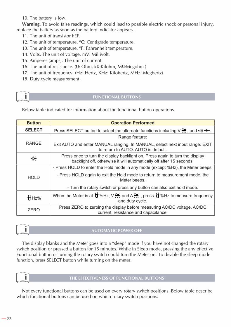
Not every functional buttons can be used on every rotary switch positions. Below table describe which functional buttons can be used on which rotary switch positions.
23
Rotary Switch
Positions
Functional Buttons
SELECT RANGE HOLD %Hz ZERO
V ● ● ● ● ● ●
● N/A ● ● N/A ●Ω N/A ● ● ● N/A ●
%Hz N/A N/A ● N/A ● N/A
40A ● N/A ● ● ● ●
400A ● N/A ● ● ● ●
1000A ● N/A ● ● ● ●ºC N/A N/A ● ● N/A N/A
MEASUREMENT OPERATION
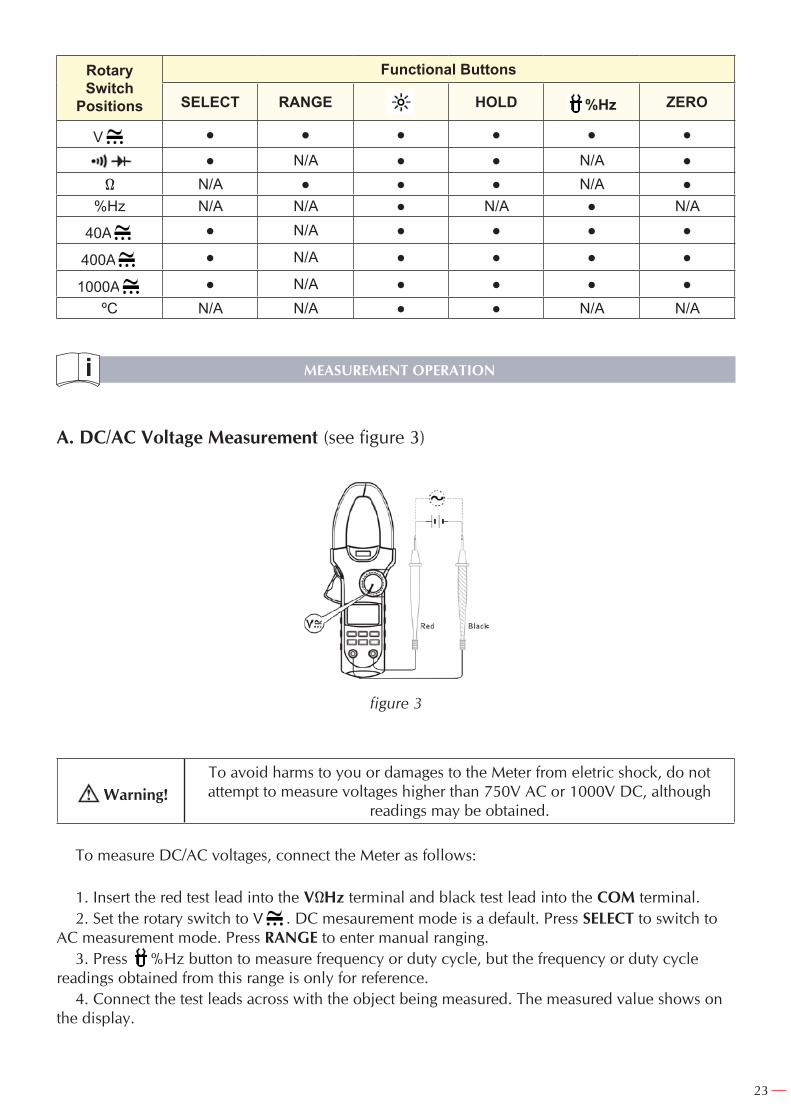
A. DC/AC Voltage Measurement (see figure 3)
figure 3
Warning!To avoid harms to you or damages to the Meter from eletric shock, do not attempt to measure voltages higher than 750V AC or 1000V DC, although
readings may be obtained.
To measure DC/AC voltages, connect the Meter as follows:
1. Insert the red test lead into the VΩHz terminal and black test lead into the COM terminal.2. Set the rotary switch to V . DC mesaurement mode is a default. Press SELECT to switch to
AC measurement mode. Press RANGE to enter manual ranging.3. Press %Hz button to measure frequency or duty cycle, but the frequency or duty cycle
readings obtained from this range is only for reference.4. Connect the test leads across with the object being measured. The measured value shows on
the display.
24
Note:- AC Millivolt is a manual ranging measurement mode.- In each range, the Meter has an input impedance of 10MΩ. This loading effect can cause
measurement errors in high impedance circuits. If the circuit impedance is less than or equal to 10kΩ, the error is negligible (0.1% or less).
- When DC/AC voltage measurement has been completed, disconnect the connection between the testing leads and the circuit under test and remove testing leads from the input terminals.
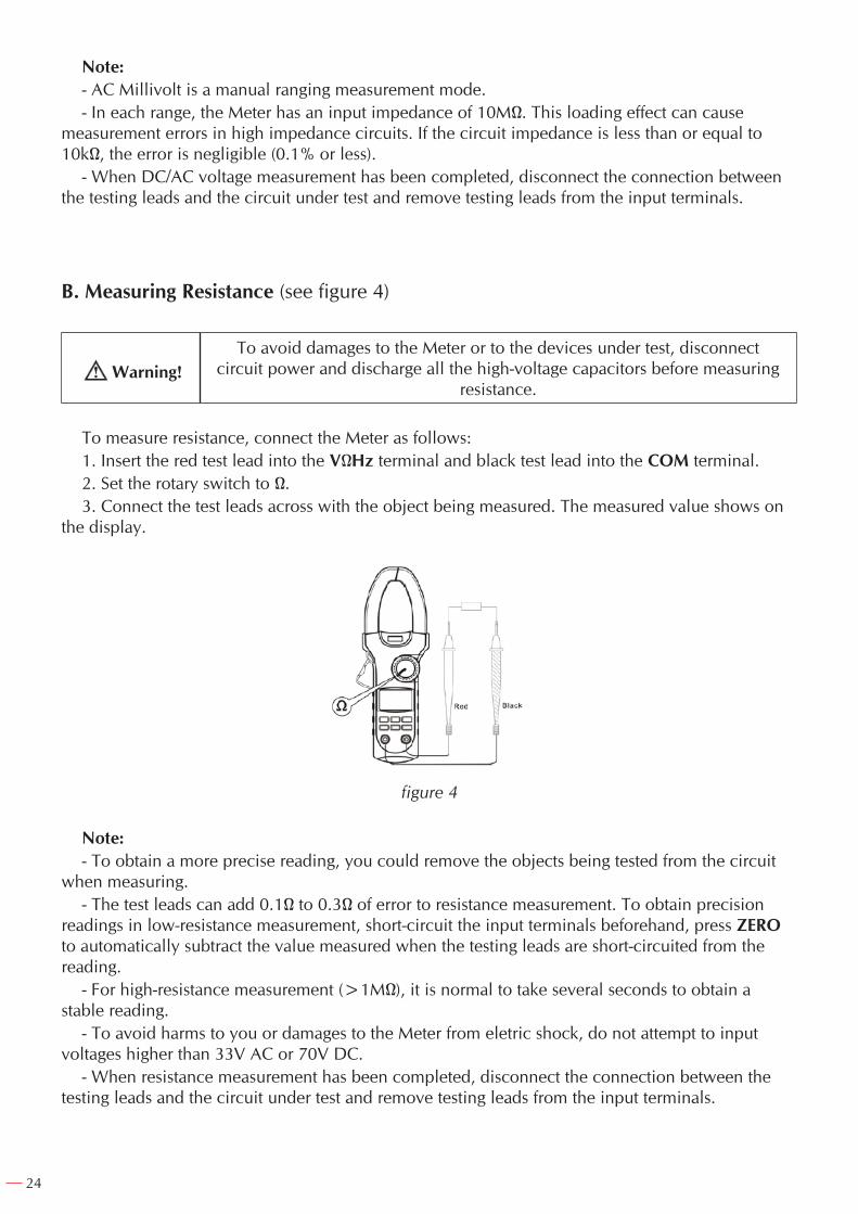
B. Measuring Resistance (see figure 4)
Warning!To avoid damages to the Meter or to the devices under test, disconnect
circuit power and discharge all the high-voltage capacitors before measuring resistance.
To measure resistance, connect the Meter as follows:1. Insert the red test lead into the VΩHz terminal and black test lead into the COM terminal.2. Set the rotary switch to Ω.3. Connect the test leads across with the object being measured. The measured value shows on
the display.
figure 4
Note:- To obtain a more precise reading, you could remove the objects being tested from the circuit
when measuring.- The test leads can add 0.1Ω to 0.3Ω of error to resistance measurement. To obtain precision
readings in low-resistance measurement, short-circuit the input terminals beforehand, press ZERO to automatically subtract the value measured when the testing leads are short-circuited from the reading.
- For high-resistance measurement (>1MΩ), it is normal to take several seconds to obtain a stable reading.
- To avoid harms to you or damages to the Meter from eletric shock, do not attempt to input voltages higher than 33V AC or 70V DC.
- When resistance measurement has been completed, disconnect the connection between the testing leads and the circuit under test and remove testing leads from the input terminals.
25
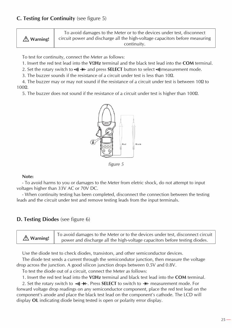
C. Testing for Continuity (see figure 5)
Warning!To avoid damages to the Meter or to the devices under test, disconnect
circuit power and discharge all the high-voltage capacitors before measuring continuity.
To test for continuity, connect the Meter as follows:1. Insert the red test lead into the VΩHz terminal and the black test lead into the COM terminal.2. Set the rotary switch to and press SELECT button to select measurement mode.3. The buzzer sounds if the resistance of a circuit under test is less than 10Ω.4. The buzzer may or may not sound if the resistance of a circuit under test is between 10Ω to
100Ω.5. The buzzer does not sound if the resistance of a circuit under test is higher than 100Ω.
figure 5
Note:- To avoid harms to you or damages to the Meter from eletric shock, do not attempt to input
voltages higher than 33V AC or 70V DC.- When continuity testing has been completed, disconnect the connection between the testing
leads and the circuit under test and remove testing leads from the input terminals.
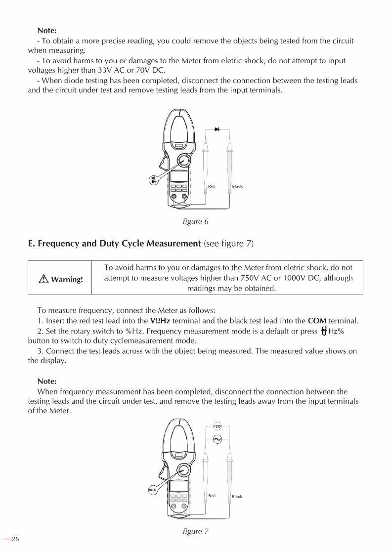
D. Testing Diodes (see figure 6)
Warning!To avoid damages to the Meter or to the devices under test, disconnect circuit
power and discharge all the high-voltage capacitors before testing diodes.
Use the diode test to check diodes, transistors, and other semiconductor devices.The diode test sends a current through the semicondutor junction, then measure the voltage
drop across the junction. A good silicon junction drops between 0.5V and 0.8V.To test the diode out of a circuit, connect the Meter as follows:1. Insert the red test lead into the VΩHz terminal and black test lead into the COM terminal.2. Set the rotary switch to . Press SELECT to switch to measurement mode. For
forward voltage drop readings on any semiconductor component, place the red test lead on the component’s anode and place the black test lead on the component’s cathode. The LCD will display OL indicating diode being tested is open or polarity error display.
26
Note:- To obtain a more precise reading, you could remove the objects being tested from the circuit
when measuring.- To avoid harms to you or damages to the Meter from eletric shock, do not attempt to input
voltages higher than 33V AC or 70V DC.- When diode testing has been completed, disconnect the connection between the testing leads
and the circuit under test and remove testing leads from the input terminals.
figure 6
E. Frequency and Duty Cycle Measurement (see figure 7)
Warning!To avoid harms to you or damages to the Meter from eletric shock, do notattempt to measure voltages higher than 750V AC or 1000V DC, although
readings may be obtained.
To measure frequency, connect the Meter as follows:1. Insert the red test lead into the VΩHz terminal and the black test lead into the COM terminal.2. Set the rotary switch to %Hz. Frequency measurement mode is a default or press Hz%
button to switch to duty cyclemeasurement mode.3. Connect the test leads across with the object being measured. The measured value shows on
the display.
Note:When frequency measurement has been completed, disconnect the connection between the
testing leads and the circuit under test, and remove the testing leads away from the input terminals of the Meter.
figure 7
27
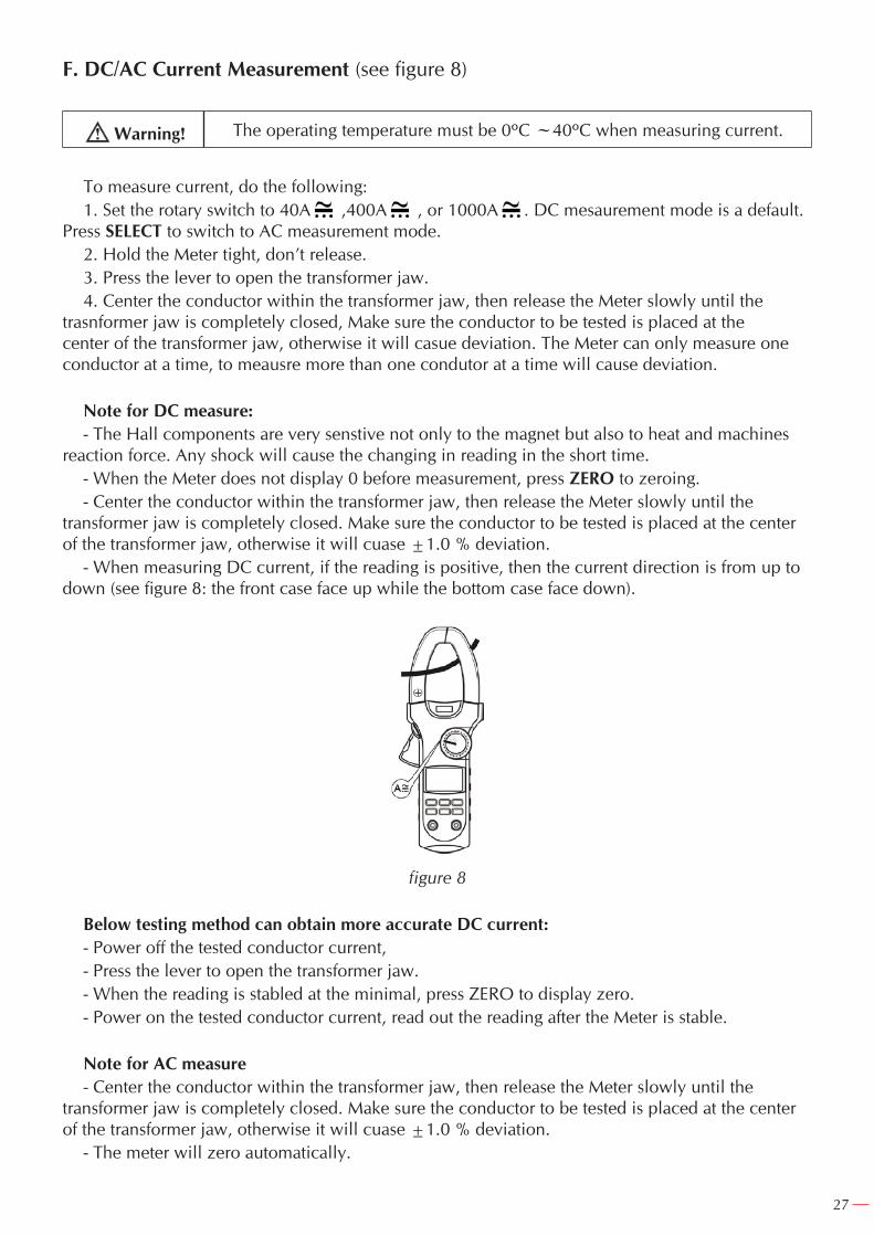
F. DC/AC Current Measurement (see figure 8)
Warning! The operating temperature must be 0ºC ~40ºC when measuring current.
To measure current, do the following:1. Set the rotary switch to 40A ,400A , or 1000A . DC mesaurement mode is a default.
Press SELECT to switch to AC measurement mode.2. Hold the Meter tight, don’t release.3. Press the lever to open the transformer jaw.4. Center the conductor within the transformer jaw, then release the Meter slowly until the
trasnformer jaw is completely closed, Make sure the conductor to be tested is placed at the center of the transformer jaw, otherwise it will casue deviation. The Meter can only measure one conductor at a time, to meausre more than one condutor at a time will cause deviation.
Note for DC measure:- The Hall components are very senstive not only to the magnet but also to heat and machines
reaction force. Any shock will cause the changing in reading in the short time.- When the Meter does not display 0 before measurement, press ZERO to zeroing.- Center the conductor within the transformer jaw, then release the Meter slowly until the
transformer jaw is completely closed. Make sure the conductor to be tested is placed at the center of the transformer jaw, otherwise it will cuase ±1.0 % deviation.
- When measuring DC current, if the reading is positive, then the current direction is from up to down (see figure 8: the front case face up while the bottom case face down).
figure 8
Below testing method can obtain more accurate DC current:- Power off the tested conductor current,- Press the lever to open the transformer jaw.- When the reading is stabled at the minimal, press ZERO to display zero.- Power on the tested conductor current, read out the reading after the Meter is stable.
Note for AC measure- Center the conductor within the transformer jaw, then release the Meter slowly until the
transformer jaw is completely closed. Make sure the conductor to be tested is placed at the center of the transformer jaw, otherwise it will cuase ±1.0 % deviation.
- The meter will zero automatically.
28
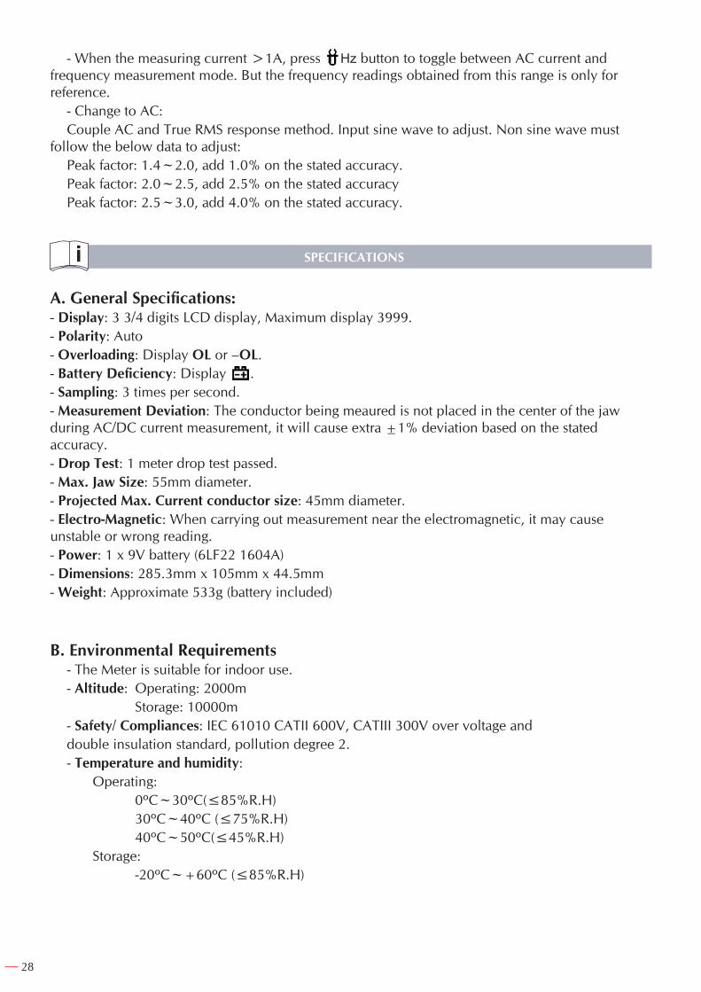
- When the measuring current >1A, press Hz button to toggle between AC current and frequency measurement mode. But the frequency readings obtained from this range is only for reference.
- Change to AC:Couple AC and True RMS response method. Input sine wave to adjust. Non sine wave must
follow the below data to adjust:Peak factor: 1.4~2.0, add 1.0% on the stated accuracy.Peak factor: 2.0~2.5, add 2.5% on the stated accuracyPeak factor: 2.5~3.0, add 4.0% on the stated accuracy.
SPECIFICATIONS
A. General Specifications:- Display: 3 3/4 digits LCD display, Maximum display 3999.- Polarity: Auto- Overloading: Display OL or –OL.- Battery Deficiency: Display .- Sampling: 3 times per second.- Measurement Deviation: The conductor being meaured is not placed in the center of the jaw during AC/DC current measurement, it will cause extra ±1% deviation based on the stated accuracy.- Drop Test: 1 meter drop test passed.- Max. Jaw Size: 55mm diameter.- Projected Max. Current conductor size: 45mm diameter.- Electro-Magnetic: When carrying out measurement near the electromagnetic, it may cause unstable or wrong reading.- Power: 1 x 9V battery (6LF22 1604A)- Dimensions: 285.3mm x 105mm x 44.5mm- Weight: Approximate 533g (battery included)
B. Environmental Requirements- The Meter is suitable for indoor use.- Altitude: Operating: 2000m Storage: 10000m- Safety/ Compliances: IEC 61010 CATII 600V, CATIII 300V over voltage anddouble insulation standard, pollution degree 2.- Temperature and humidity: Operating: 0ºC~30ºC(≤85%R.H) 30ºC~40ºC (≤75%R.H) 40ºC~50ºC(≤45%R.H) Storage: -20ºC~+60ºC (≤85%R.H)
29
ACCURATE SPECIFICATIONS
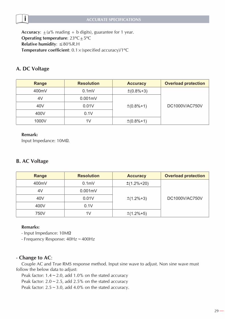
Accuracy: ±(a% reading + b digits), guarantee for 1 year.Operating temperature: 23ºC±5ºCRelative humidity: ≤80%R.HTemperature coefficient: 0.1×(specified accuracy)/1ºC
A. DC Voltage
Range Resolution Accuracy Overload protection400mV 0.1mV (0.8%+3)
DC1000V/AC750V
4V 0.001mV
(0.8%+1)40V 0.01V
400V 0.1V
1000V 1V (0.8%+1)
Remark: Input Impedance: 10MΩ.
B. AC Voltage
Range Resolution Accuracy Overload protection400mV 0.1mV (1.2%+20)
DC1000V/AC750V
4V 0.001mV
(1.2%+3)40V 0.01V
400V 0.1V
750V 1V (1.2%+5)
Remarks:- Input Impedance: 10MΩ- Frequency Response: 40Hz~400Hz
- Change to AC:Couple AC and True RMS response method. Input sine wave to adjust. Non sine wave must
follow the below data to adjust:Peak factor: 1.4~2.0, add 1.0% on the stated accuracyPeak factor: 2.0~2.5, add 2.5% on the stated accuracyPeak factor: 2.5~3.0, add 4.0% on the stated accuracy.
30
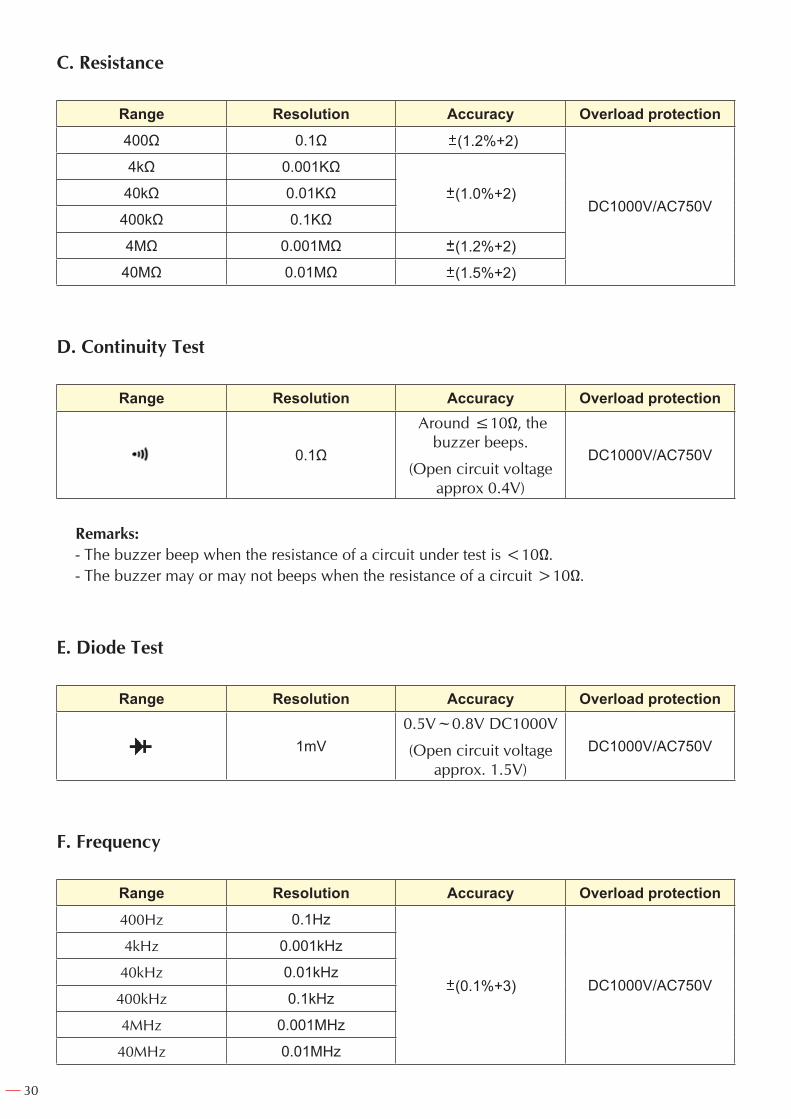
C. Resistance
Range Resolution Accuracy Overload protection400Ω 0.1Ω (1.2%+2)
DC1000V/AC750V
4kΩ 0.001KΩ
(1.0%+2)40kΩ 0.01KΩ
400kΩ 0.1KΩ
4MΩ 0.001MΩ (1.2%+2)
40MΩ 0.01MΩ (1.5%+2)
D. Continuity Test
Range Resolution Accuracy Overload protection
0.1Ω
Around ≤10Ω, the buzzer beeps.
(Open circuit voltage approx 0.4V)
DC1000V/AC750V
Remarks:- The buzzer beep when the resistance of a circuit under test is <10Ω.- The buzzer may or may not beeps when the resistance of a circuit >10Ω.
E. Diode Test
Range Resolution Accuracy Overload protection
1mV0.5V~0.8V DC1000V
(Open circuit voltage approx. 1.5V)
DC1000V/AC750V
F. Frequency
Range Resolution Accuracy Overload protection400Hz 0.1Hz
(0.1%+3) DC1000V/AC750V
4kHz 0.001kHz
40kHz 0.01kHz
400kHz 0.1kHz
4MHz 0.001MHz
40MHz 0.01MHz
31
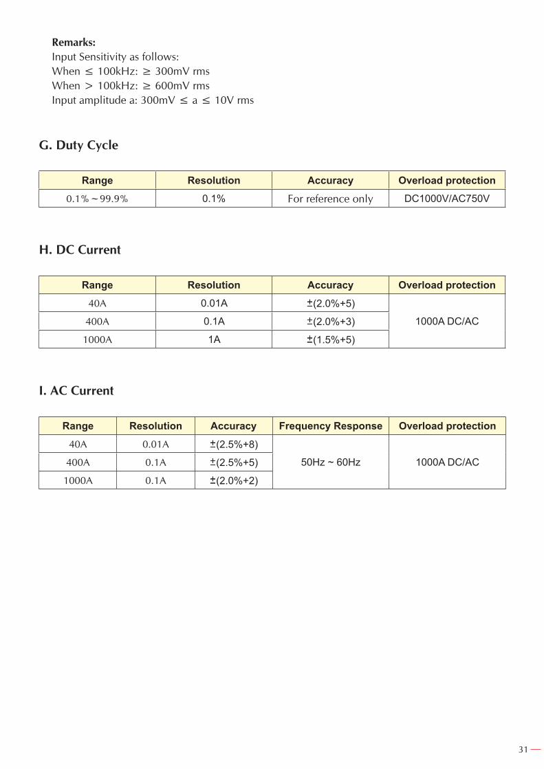
Remarks:Input Sensitivity as follows:When ≤ 100kHz: ≥ 300mV rmsWhen > 100kHz: ≥ 600mV rmsInput amplitude a: 300mV ≤ a ≤ 10V rms
G. Duty Cycle
Range Resolution Accuracy Overload protection0.1%~99.9% 0.1% For reference only DC1000V/AC750V
H. DC Current
Range Resolution Accuracy Overload protection40A 0.01A (2.0%+5)
1000A DC/AC400A 0.1A (2.0%+3)
1000A 1A (1.5%+5)
I. AC Current
Range Resolution Accuracy Frequency Response Overload protection40A 0.01A (2.5%+8)
50Hz ~ 60Hz 1000A DC/AC400A 0.1A (2.5%+5)
1000A 0.1A (2.0%+2)
32
MAINTENANCE
This section provides basic maintenance information including battery replacement instruction.
Warning!Do not attempt to repair or service your Meter unless you are qualified to do so
and have the relevant calibration, performance test, and service information.
To avoid electrical shock or damage to the Meter, do not get water inside the case.
A. General Service- Periodically wipe the case with a damp cloth and mild detergent. Do not use abrasives or
solvents.- To clean the terminals with cotton bar with detergent, as dirt or moisture in the terminals can
affect readings.- Turn the Meter power off when it is not in use.- Take out the battery when it is not using for a long time.- Do not use or store the Meter in a place of humidity, high temperature, explosive, inflammable
and strong magnetic field.
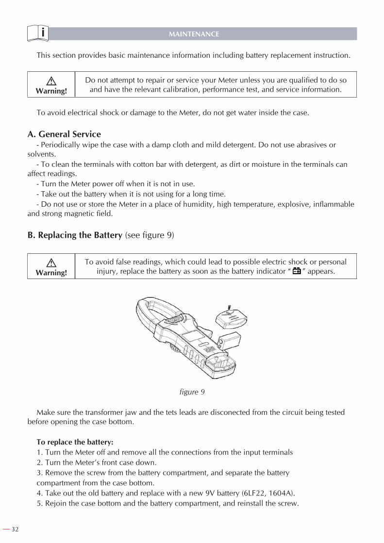
B. Replacing the Battery (see figure 9)
Warning!To avoid false readings, which could lead to possible electric shock or personal
injury, replace the battery as soon as the battery indicator “ ” appears.
figure 9
Make sure the transformer jaw and the tets leads are disconected from the circuit being tested before opening the case bottom.
To replace the battery:1. Turn the Meter off and remove all the connections from the input terminals2. Turn the Meter’s front case down.3. Remove the screw from the battery compartment, and separate the batterycompartment from the case bottom.4. Take out the old battery and replace with a new 9V battery (6LF22, 1604A).5. Rejoin the case bottom and the battery compartment, and reinstall the screw.
33
NOTES
IMPORTANT!
The maker will not take responsibility for damage or malfunction as a result of the device being incorrectly used or, applied for a purpose for whith it was not intended.
According to Waste Electrical and Electronic Equipment directive (WEEE), these ones must be collected and arranged separately. If you have to throw them out, please, do not use the usual rubbish. Please, contact your distributor for free recycling.
GUARANTEE
The maker guarantees to the device owner 12 months against any manufacture defect.This guarantee do not cover the parts wich are consumables.
Note: to apply the guarantee its necesary to send the “GUARANTEE CERTIFICATE” duly filled within one week after purchased the machine to the maker.

34
ARTICULO / ITEM / ARTICLE: ....................................................................................................................
Nº DE SERIE / SERIE Nº / Nº SERIE: ...........................................................................................................
DISTRIBUIDOR / DISTRIBUTOR / DISTRIBUTEUR: ...................................................................................
PAIS / COUNTRY / PAYS: .............................................................................TEL.:....................................
FECHA DE VENTA / SALE DATE / DATE VENTE: ........................................................................................
NOMBRE DEL COMPRADOR / BUYER NAME / NOM DE L’ACHETEUR: ..................................................
TEL. COMPRADOR / BUYER TEL. / TEL. DE L’ACHETEUR: ........................................................................
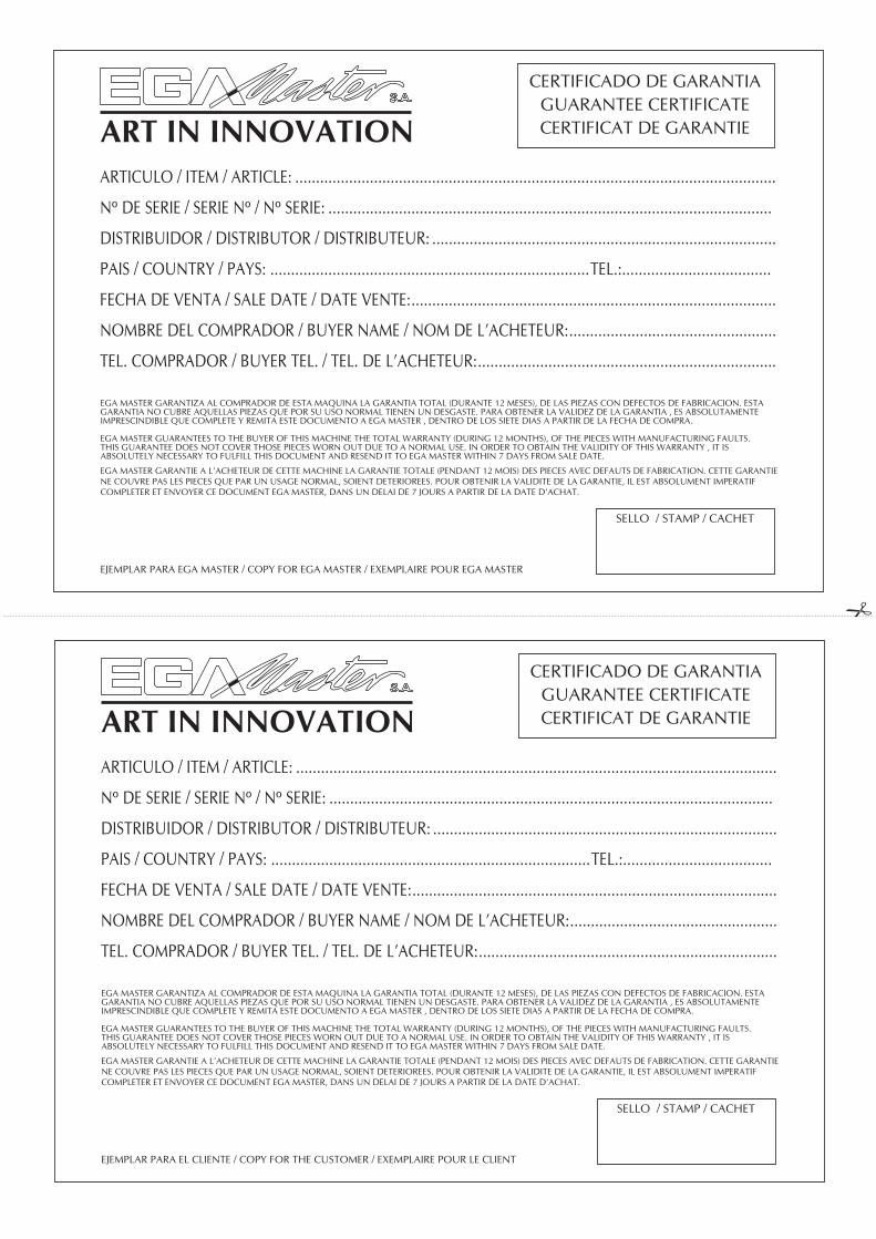
CERTIFICADO DE GARANTIAGUARANTEE CERTIFICATECERTIFICAT DE GARANTIE
SELLO / STAMP / CACHET
EGA MASTER GARANTIZA AL COMPRADOR DE ESTA MAQUINA LA GARANTIA TOTAL (DURANTE 12 MESES), DE LAS PIEZAS CON DEFECTOS DE FABRICACION. ESTA GARANTIA NO CUBRE AQUELLAS PIEZAS QUE POR SU USO NORMAL TIENEN UN DESGASTE. PARA OBTENER LA VALIDEZ DE LA GARANTIA , ES ABSOLUTAMENTE IMPRESCINDIBLE QUE COMPLETE Y REMITA ESTE DOCUMENTO A EGA MASTER , DENTRO DE LOS SIETE DIAS A PARTIR DE LA FECHA DE COMPRA.
EGA MASTER GUARANTEES TO THE BUYER OF THIS MACHINE THE TOTAL WARRANTY (DURING 12 MONTHS), OF THE PIECES WITH MANUFACTURING FAULTS.THIS GUARANTEE DOES NOT COVER THOSE PIECES WORN OUT DUE TO A NORMAL USE. IN ORDER TO OBTAIN THE VALIDITY OF THIS WARRANTY , IT IS ABSOLUTELY NECESSARY TO FULFILL THIS DOCUMENT AND RESEND IT TO EGA MASTER WITHIN 7 DAYS FROM SALE DATE.
EGA MASTER GARANTIE A L’ACHETEUR DE CETTE MACHINE LA GARANTIE TOTALE (PENDANT 12 MOIS) DES PIECES AVEC DEFAUTS DE FABRICATION. CETTE GARANTIE NE COUVRE PAS LES PIECES QUE PAR UN USAGE NORMAL, SOIENT DETERIOREES. POUR OBTENIR LA VALIDITE DE LA GARANTIE, IL EST ABSOLUMENT IMPERATIF COMPLETER ET ENVOYER CE DOCUMENT EGA MASTER, DANS UN DELAI DE 7 JOURS A PARTIR DE LA DATE D’ACHAT.
EJEMPLAR PARA EGA MASTER / COPY FOR EGA MASTER / EXEMPLAIRE POUR EGA MASTER
ARTICULO / ITEM / ARTICLE: ....................................................................................................................
Nº DE SERIE / SERIE Nº / Nº SERIE: ...........................................................................................................
DISTRIBUIDOR / DISTRIBUTOR / DISTRIBUTEUR: ...................................................................................
PAIS / COUNTRY / PAYS: .............................................................................TEL.:....................................
FECHA DE VENTA / SALE DATE / DATE VENTE: ........................................................................................
NOMBRE DEL COMPRADOR / BUYER NAME / NOM DE L’ACHETEUR: ..................................................
TEL. COMPRADOR / BUYER TEL. / TEL. DE L’ACHETEUR: ........................................................................
CERTIFICADO DE GARANTIAGUARANTEE CERTIFICATECERTIFICAT DE GARANTIE
SELLO / STAMP / CACHET
EGA MASTER GARANTIZA AL COMPRADOR DE ESTA MAQUINA LA GARANTIA TOTAL (DURANTE 12 MESES), DE LAS PIEZAS CON DEFECTOS DE FABRICACION. ESTA GARANTIA NO CUBRE AQUELLAS PIEZAS QUE POR SU USO NORMAL TIENEN UN DESGASTE. PARA OBTENER LA VALIDEZ DE LA GARANTIA , ES ABSOLUTAMENTE IMPRESCINDIBLE QUE COMPLETE Y REMITA ESTE DOCUMENTO A EGA MASTER , DENTRO DE LOS SIETE DIAS A PARTIR DE LA FECHA DE COMPRA.
EGA MASTER GUARANTEES TO THE BUYER OF THIS MACHINE THE TOTAL WARRANTY (DURING 12 MONTHS), OF THE PIECES WITH MANUFACTURING FAULTS.THIS GUARANTEE DOES NOT COVER THOSE PIECES WORN OUT DUE TO A NORMAL USE. IN ORDER TO OBTAIN THE VALIDITY OF THIS WARRANTY , IT IS ABSOLUTELY NECESSARY TO FULFILL THIS DOCUMENT AND RESEND IT TO EGA MASTER WITHIN 7 DAYS FROM SALE DATE.
EGA MASTER GARANTIE A L’ACHETEUR DE CETTE MACHINE LA GARANTIE TOTALE (PENDANT 12 MOIS) DES PIECES AVEC DEFAUTS DE FABRICATION. CETTE GARANTIE NE COUVRE PAS LES PIECES QUE PAR UN USAGE NORMAL, SOIENT DETERIOREES. POUR OBTENIR LA VALIDITE DE LA GARANTIE, IL EST ABSOLUMENT IMPERATIF COMPLETER ET ENVOYER CE DOCUMENT EGA MASTER, DANS UN DELAI DE 7 JOURS A PARTIR DE LA DATE D’ACHAT.
EJEMPLAR PARA EL CLIENTE / COPY FOR THE CUSTOMER / EXEMPLAIRE POUR LE CLIENT


C/ ZORROLLETA 11, POL. IND. JUNDIZ01015 VITORIA, SPAIN P.O.B. APTDO. 5005
TEL. 34 - 945 290 001 FAX. 34 - 945 290 [email protected]
www.egamaster.com