Embed Size (px)
Citation preview
GESTOR DE AVISOS
8 ZONAS
MESSAGE MANAGER
8 ZONES
SMM-8SA
Manual de instalación y funcionamiento v1.4Installation and operation manual v1.4
SMM-8SA v1.4 Página 1 de 21
SMM-8SA SCHEDULED MESSAGE MODULE GESTOR DE AVISOS
INSTRUCCIONES DE SEGURIDAD:
IMPORTANTE:
Lea atentamente las instrucciones de seguridad.
Guarde este manual para futuras consultas.
Desenchufe el equipo durante las tormentas eléctricas y cuando no se vaya a usar durante un largo período de tiempo.
Use siempre cables ya preparados para evitar riesgos de descargas eléctricas o fuego. En caso de tener dudas, consulte con un instalador cualificado.
No use el aparato en lugares húmedos o cerca de líquidos. No instale el aparato cerca de fuentes de calor. No bloquee los orificios de ventilación.
Cuando sea necesario, retire el polvo con un paño seco. No use disolventes como el alcohol. Mantenga el aparato limpio y sin polvo.
Se requiere personal cualificado para realizar todas las operaciones de mantenimiento. Nota: La información proporcionada por este manual no incluye detalles de diseño, producción o variaciones en el equipo. Tampoco incluye posibles situaciones de riesgo durante la instalación, funcionamiento o mantenimiento. Si usted necesita asistencia especial más allá del manual, por favor contacte con nuestro servicio técnico.
SMM-8SA v1.4 Página 2 de 21
SMM-8SA SCHEDULED MESSAGE MODULE GESTOR DE AVISOS
ÍNDICE 1. INFORMACIÓN GENERAL .......................................................................................... 3 2. FUNCIONAMIENTO..................................................................................................... 4
2.1 PANEL FRONTAL ................................................................................................. 4 2.2 PANEL POSTERIOR ............................................................................................ 5
3. EJEMPLO DE CONEXIÓN .......................................................................................... 7 4. CONFIGURACIÓN DEL EQUIPO ................................................................................ 8
4.1 ACCESO AL SERVIDOR WEB ............................................................................. 8 4.2 RED ...................................................................................................................... 9 4.3 USUARIO / IDIOMA ............................................................................................ 10 4.4 FECHA Y HORA ................................................................................................. 10 4.5 CARGAR MENSAJES ........................................................................................ 11 4.6 ENVIAR MENSAJES .......................................................................................... 12 4.7 MANTENIMIENTO .............................................................................................. 12 4.8 FESTIVOS .......................................................................................................... 13 4.9 MONITORIZACIÓN ............................................................................................. 14
5. CONTACTOS DE ENTRADA ..................................................................................... 15 6. PROGRAMACIONES HORARIAS ............................................................................. 17 7. DIRECCIÓN IP POR DEFECTO. ............................................................................... 19 8. CARACTERÍSTICAS TÉCNICAS .............................................................................. 20 9. CERTIFICADO DE GARANTÍA .................................................................................. 21
SMM-8SA v1.4 Página 3 de 21
SMM-8SA SCHEDULED MESSAGE MODULE GESTOR DE AVISOS
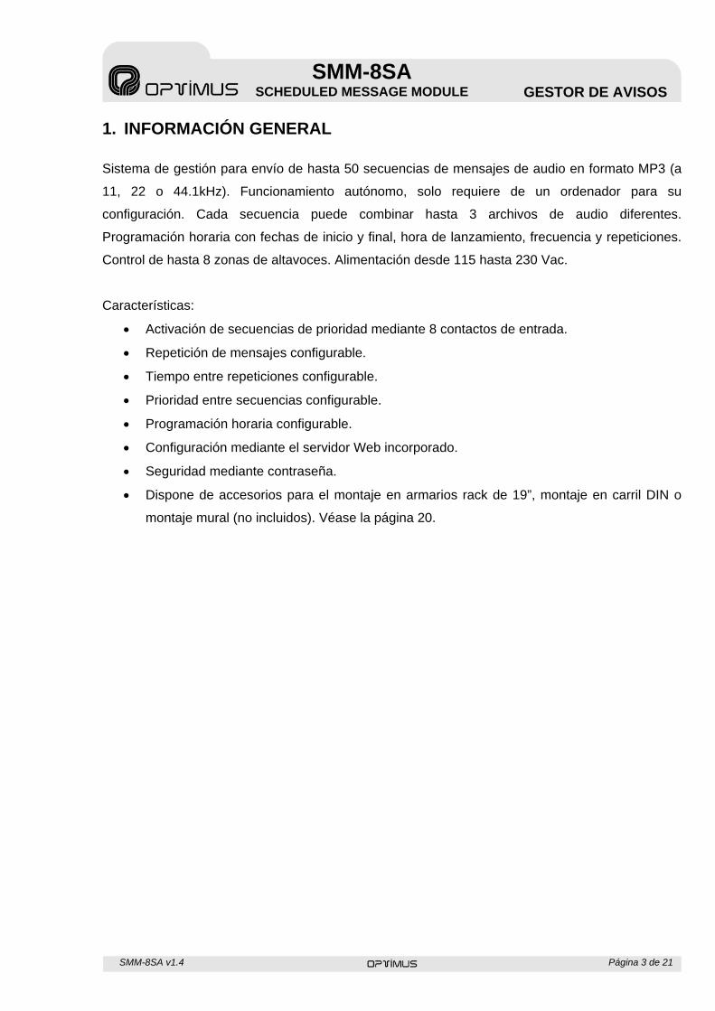
1. INFORMACIÓN GENERAL
Sistema de gestión para envío de hasta 50 secuencias de mensajes de audio en formato MP3 (a
11, 22 o 44.1kHz). Funcionamiento autónomo, solo requiere de un ordenador para su
configuración. Cada secuencia puede combinar hasta 3 archivos de audio diferentes.
Programación horaria con fechas de inicio y final, hora de lanzamiento, frecuencia y repeticiones.
Control de hasta 8 zonas de altavoces. Alimentación desde 115 hasta 230 Vac.
Características:
Activación de secuencias de prioridad mediante 8 contactos de entrada.
Repetición de mensajes configurable.
Tiempo entre repeticiones configurable.
Prioridad entre secuencias configurable.
Programación horaria configurable.
Configuración mediante el servidor Web incorporado.
Seguridad mediante contraseña.
Dispone de accesorios para el montaje en armarios rack de 19”, montaje en carril DIN o
montaje mural (no incluidos). Véase la página 20.
SMM-8SA v1.4 Página 4 de 21
SMM-8SA SCHEDULED MESSAGE MODULE GESTOR DE AVISOS
2. FUNCIONAMIENTO
2.1 PANEL FRONTAL
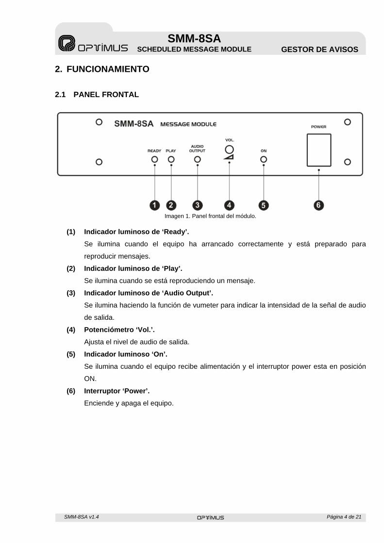
Imagen 1. Panel frontal del módulo.
(1) Indicador luminoso de ‘Ready’.
Se ilumina cuando el equipo ha arrancado correctamente y está preparado para
reproducir mensajes.
(2) Indicador luminoso de ‘Play’.
Se ilumina cuando se está reproduciendo un mensaje.
(3) Indicador luminoso de ‘Audio Output’.
Se ilumina haciendo la función de vumeter para indicar la intensidad de la señal de audio
de salida.
(4) Potenciómetro ‘Vol.’.
Ajusta el nivel de audio de salida.
(5) Indicador luminoso ‘On’.
Se ilumina cuando el equipo recibe alimentación y el interruptor power esta en posición
ON.
(6) Interruptor ‘Power’.
Enciende y apaga el equipo.
SMM-8SA v1.4 Página 5 de 21
SMM-8SA SCHEDULED MESSAGE MODULE GESTOR DE AVISOS
2.2 PANEL POSTERIOR
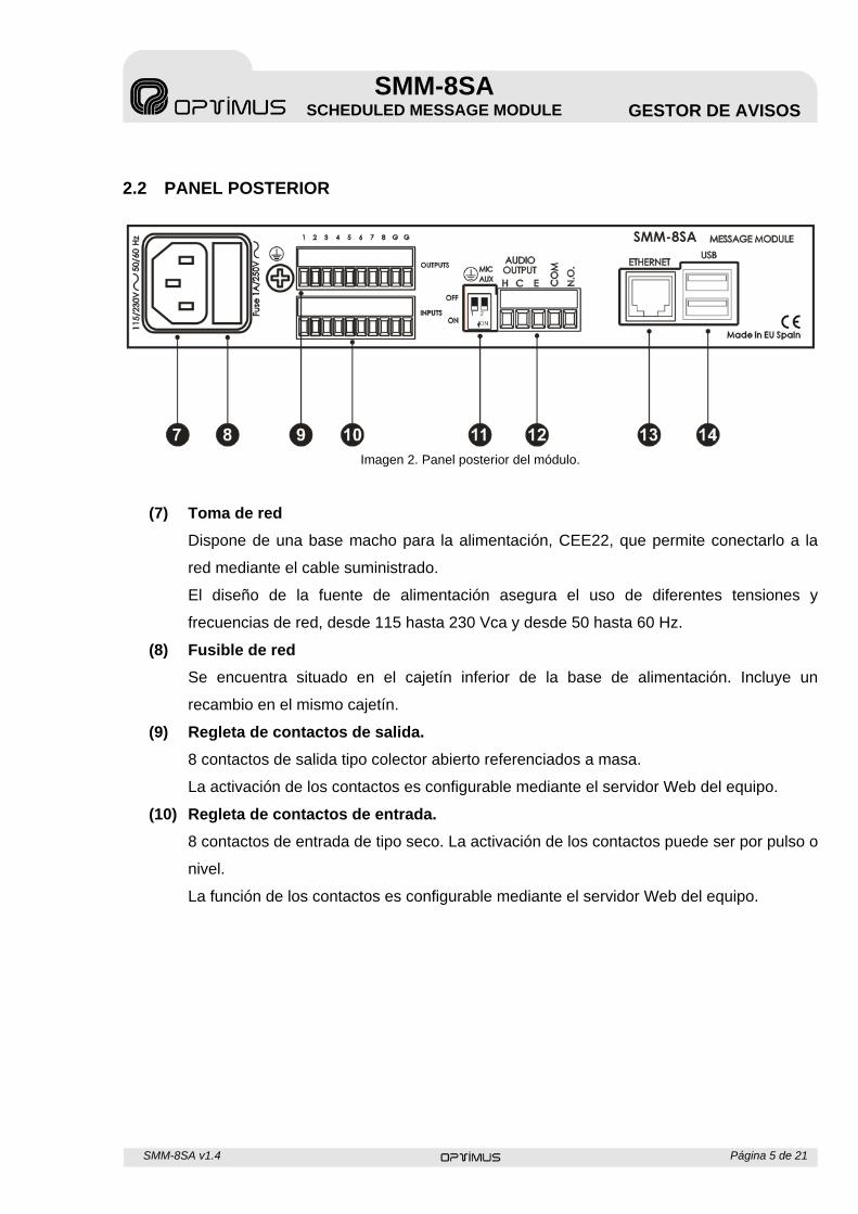
Imagen 2. Panel posterior del módulo.
(7) Toma de red
Dispone de una base macho para la alimentación, CEE22, que permite conectarlo a la
red mediante el cable suministrado.
El diseño de la fuente de alimentación asegura el uso de diferentes tensiones y
frecuencias de red, desde 115 hasta 230 Vca y desde 50 hasta 60 Hz.
(8) Fusible de red
Se encuentra situado en el cajetín inferior de la base de alimentación. Incluye un
recambio en el mismo cajetín.
(9) Regleta de contactos de salida.
8 contactos de salida tipo colector abierto referenciados a masa.
La activación de los contactos es configurable mediante el servidor Web del equipo.
(10) Regleta de contactos de entrada.
8 contactos de entrada de tipo seco. La activación de los contactos puede ser por pulso o
nivel.
La función de los contactos es configurable mediante el servidor Web del equipo.
SMM-8SA v1.4 Página 6 de 21
SMM-8SA SCHEDULED MESSAGE MODULE GESTOR DE AVISOS
(11) Dipswitch de nivel de salida y unión a GND
Si el dipswitch 1 está en ON se unen el chasis con el GND interno del equipo, si está en
OFF se separan, esto puede solucionar problemas de ruido en algunas instalaciones.
El dipswitch 2 configura el nivel de salida de audio, si está en posición ON el nivel de
salida es AUX 0 dB (775 mV) en cambio si está en OFF el nivel será MIC -60 dB (0,775
mV).
Nota: Se recomienda la configuración AUX 0dB por tener una mejor relación señal-ruido.
(12) Regleta salida de audio.
Salida de audio balanceada por transformador. Incorpora un contacto normalmente
abierto que se activa siempre que el equipo reproduzca un mensaje de audio.
(13) Conector Ethernet
Permite la conexión del equipo a un switch o un router para poder acceder al mismo por
servidor Web y configurar las funcionalidades.
(14) Conectores USB
Actualmente no tienen ninguna funcionalidad asociada.
SMM-8SA v1.4 Página 7 de 21
SMM-8SA SCHEDULED MESSAGE MODULE GESTOR DE AVISOS
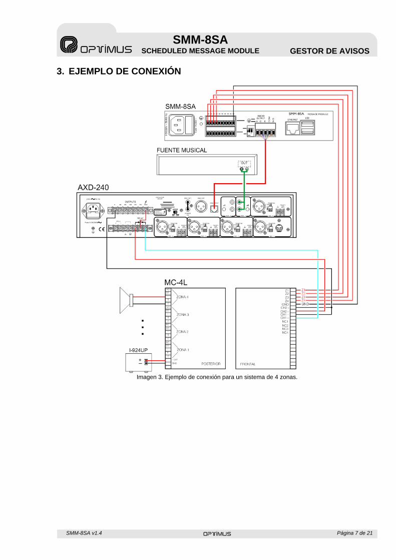
3. EJEMPLO DE CONEXIÓN
Imagen 3. Ejemplo de conexión para un sistema de 4 zonas.
SMM-8SA v1.4 Página 8 de 21
SMM-8SA SCHEDULED MESSAGE MODULE GESTOR DE AVISOS
4. CONFIGURACIÓN DEL EQUIPO
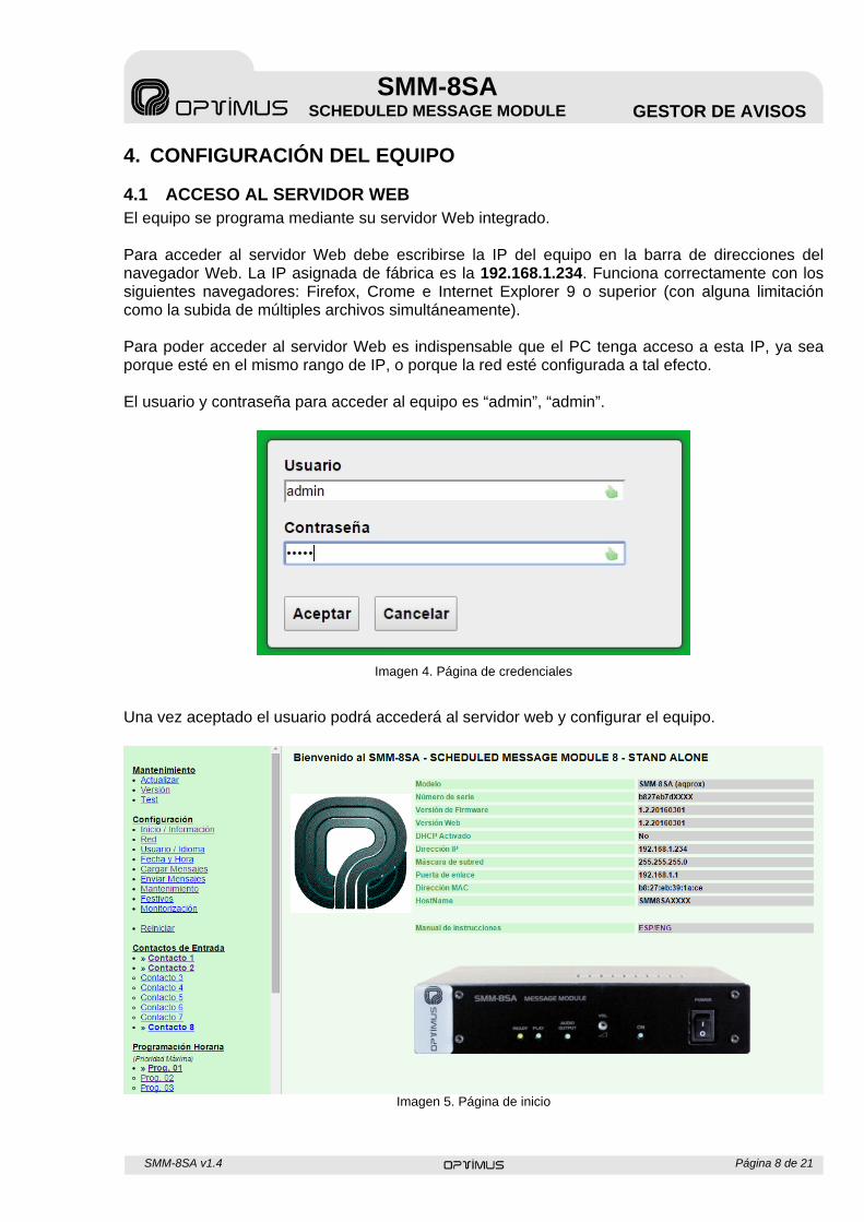
4.1 ACCESO AL SERVIDOR WEB El equipo se programa mediante su servidor Web integrado. Para acceder al servidor Web debe escribirse la IP del equipo en la barra de direcciones del navegador Web. La IP asignada de fábrica es la 192.168.1.234. Funciona correctamente con los siguientes navegadores: Firefox, Crome e Internet Explorer 9 o superior (con alguna limitación como la subida de múltiples archivos simultáneamente). Para poder acceder al servidor Web es indispensable que el PC tenga acceso a esta IP, ya sea porque esté en el mismo rango de IP, o porque la red esté configurada a tal efecto. El usuario y contraseña para acceder al equipo es “admin”, “admin”.
Imagen 4. Página de credenciales
Una vez aceptado el usuario podrá accederá al servidor web y configurar el equipo.
Imagen 5. Página de inicio
SMM-8SA v1.4 Página 9 de 21
SMM-8SA SCHEDULED MESSAGE MODULE GESTOR DE AVISOS
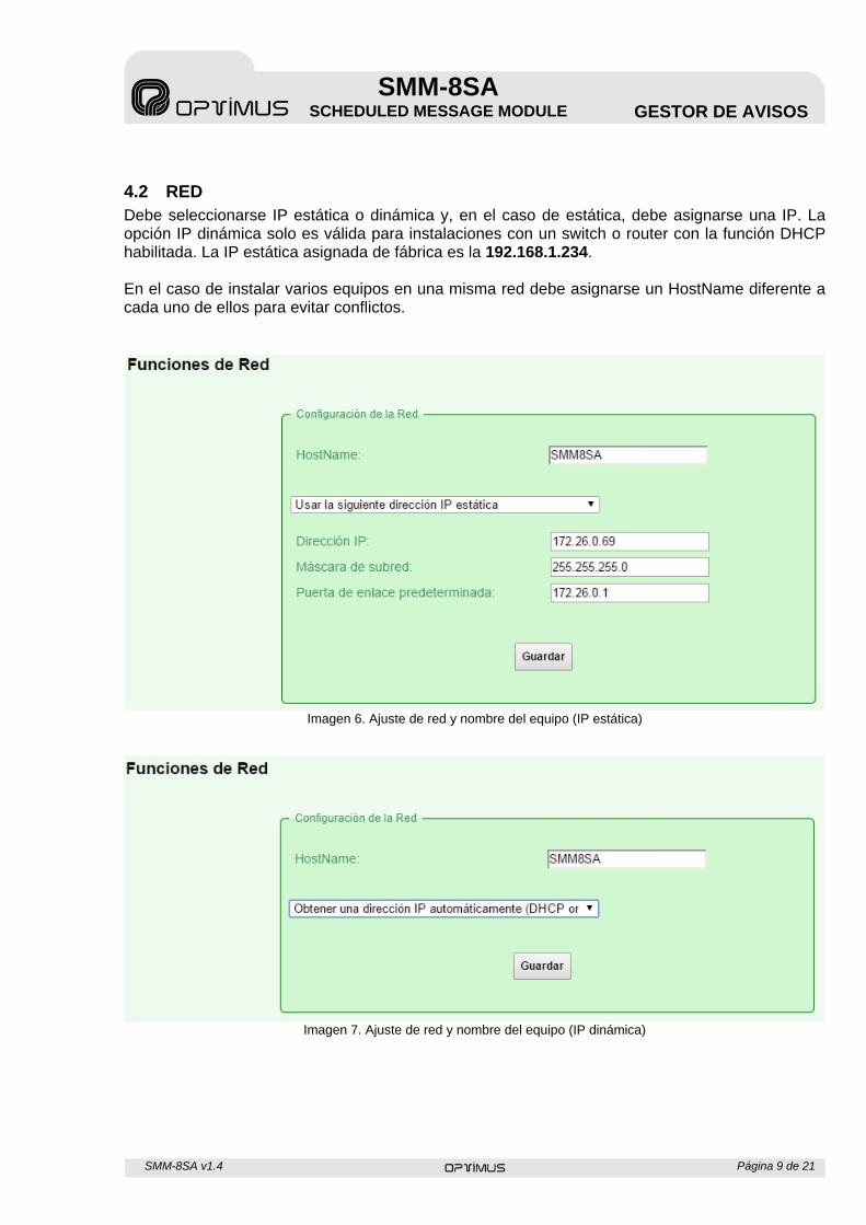
4.2 RED Debe seleccionarse IP estática o dinámica y, en el caso de estática, debe asignarse una IP. La opción IP dinámica solo es válida para instalaciones con un switch o router con la función DHCP habilitada. La IP estática asignada de fábrica es la 192.168.1.234. En el caso de instalar varios equipos en una misma red debe asignarse un HostName diferente a cada uno de ellos para evitar conflictos.
Imagen 6. Ajuste de red y nombre del equipo (IP estática)
Imagen 7. Ajuste de red y nombre del equipo (IP dinámica)
SMM-8SA v1.4 Página 10 de 21
SMM-8SA SCHEDULED MESSAGE MODULE GESTOR DE AVISOS
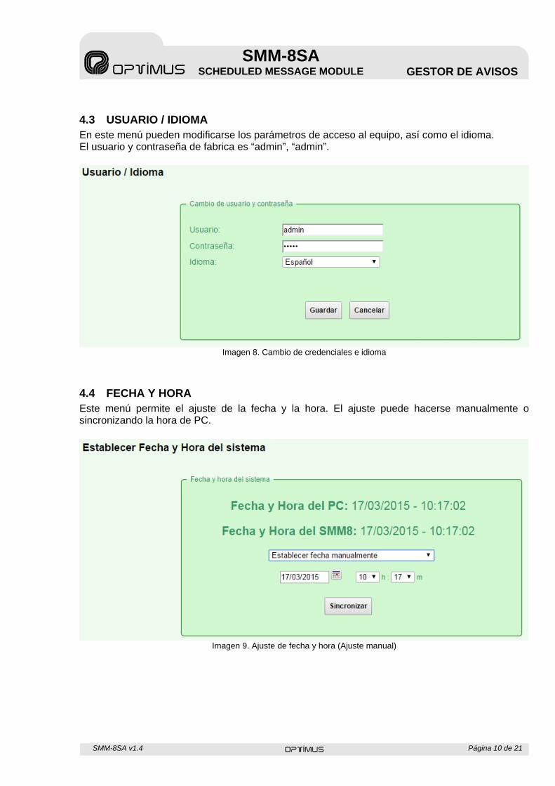
4.3 USUARIO / IDIOMA En este menú pueden modificarse los parámetros de acceso al equipo, así como el idioma. El usuario y contraseña de fabrica es “admin”, “admin”.
Imagen 8. Cambio de credenciales e idioma
4.4 FECHA Y HORA Este menú permite el ajuste de la fecha y la hora. El ajuste puede hacerse manualmente o sincronizando la hora de PC.
Imagen 9. Ajuste de fecha y hora (Ajuste manual)
SMM-8SA v1.4 Página 11 de 21
SMM-8SA SCHEDULED MESSAGE MODULE GESTOR DE AVISOS
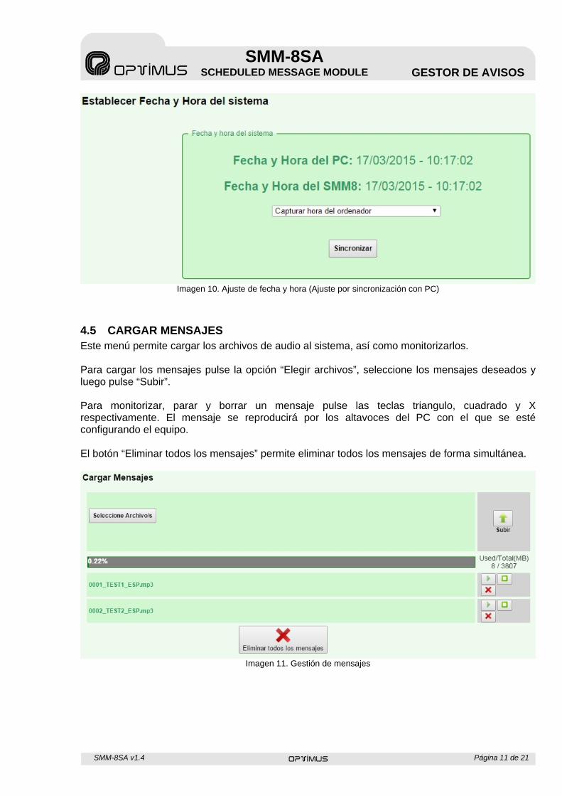
Imagen 10. Ajuste de fecha y hora (Ajuste por sincronización con PC)
4.5 CARGAR MENSAJES Este menú permite cargar los archivos de audio al sistema, así como monitorizarlos. Para cargar los mensajes pulse la opción “Elegir archivos”, seleccione los mensajes deseados y luego pulse “Subir”. Para monitorizar, parar y borrar un mensaje pulse las teclas triangulo, cuadrado y X respectivamente. El mensaje se reproducirá por los altavoces del PC con el que se esté configurando el equipo. El botón “Eliminar todos los mensajes” permite eliminar todos los mensajes de forma simultánea.
Imagen 11. Gestión de mensajes
SMM-8SA v1.4 Página 12 de 21
SMM-8SA SCHEDULED MESSAGE MODULE GESTOR DE AVISOS
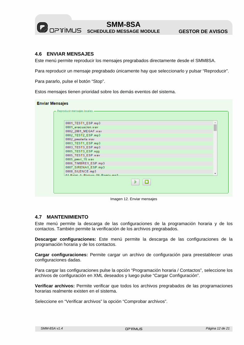
4.6 ENVIAR MENSAJES Este menú permite reproducir los mensajes pregrabados directamente desde el SMM8SA. Para reproducir un mensaje pregrabado únicamente hay que seleccionarlo y pulsar “Reproducir”. Para pararlo, pulse el botón “Stop”. Estos mensajes tienen prioridad sobre los demás eventos del sistema.
Imagen 12. Enviar mensajes
4.7 MANTENIMIENTO Este menú permite la descarga de las configuraciones de la programación horaria y de los contactos. También permite la verificación de los archivos pregrabados. Descargar configuraciones: Este menú permite la descarga de las configuraciones de la programación horaria y de los contactos. Cargar configuraciones: Permite cargar un archivo de configuración para preestablecer unas configuraciones dadas. Para cargar las configuraciones pulse la opción “Programación horaria / Contactos”, seleccione los archivos de configuración en XML deseados y luego pulse “Cargar Configuración”. Verificar archivos: Permite verificar que todos los archivos pregrabados de las programaciones horarias realmente existen en el sistema. Seleccione en “Verificar archivos” la opción “Comprobar archivos”.
SMM-8SA v1.4 Página 13 de 21
SMM-8SA SCHEDULED MESSAGE MODULE GESTOR DE AVISOS
Imagen 13. Mantenimiento
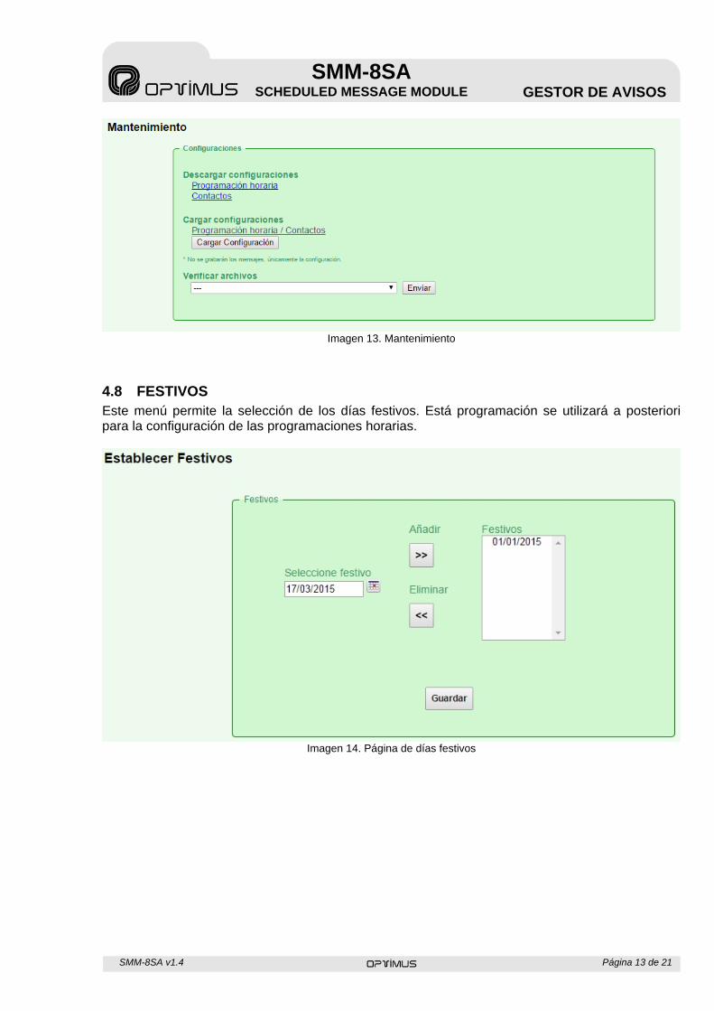
4.8 FESTIVOS Este menú permite la selección de los días festivos. Está programación se utilizará a posteriori para la configuración de las programaciones horarias.
Imagen 14. Página de días festivos
SMM-8SA v1.4 Página 14 de 21
SMM-8SA SCHEDULED MESSAGE MODULE GESTOR DE AVISOS
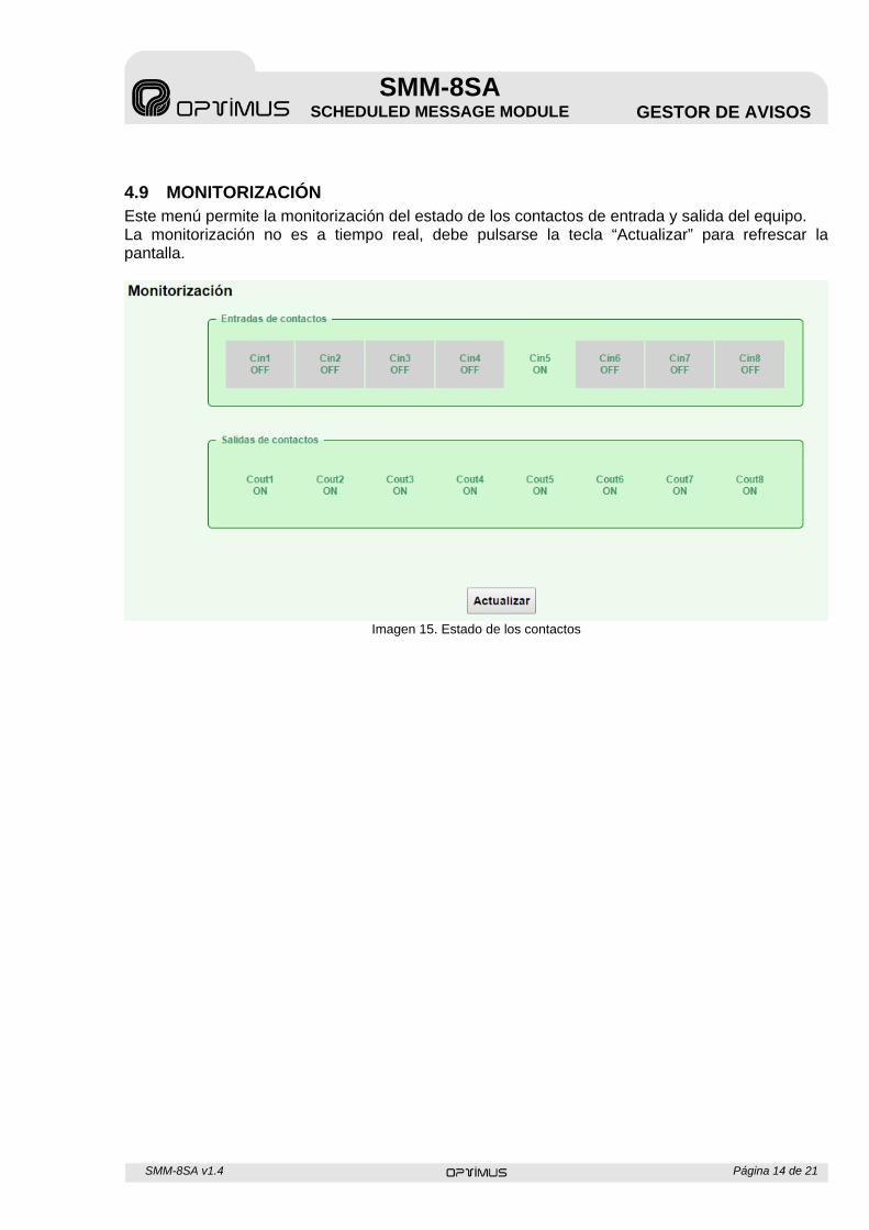
4.9 MONITORIZACIÓN Este menú permite la monitorización del estado de los contactos de entrada y salida del equipo. La monitorización no es a tiempo real, debe pulsarse la tecla “Actualizar” para refrescar la pantalla.
Imagen 15. Estado de los contactos
SMM-8SA v1.4 Página 15 de 21
SMM-8SA SCHEDULED MESSAGE MODULE GESTOR DE AVISOS
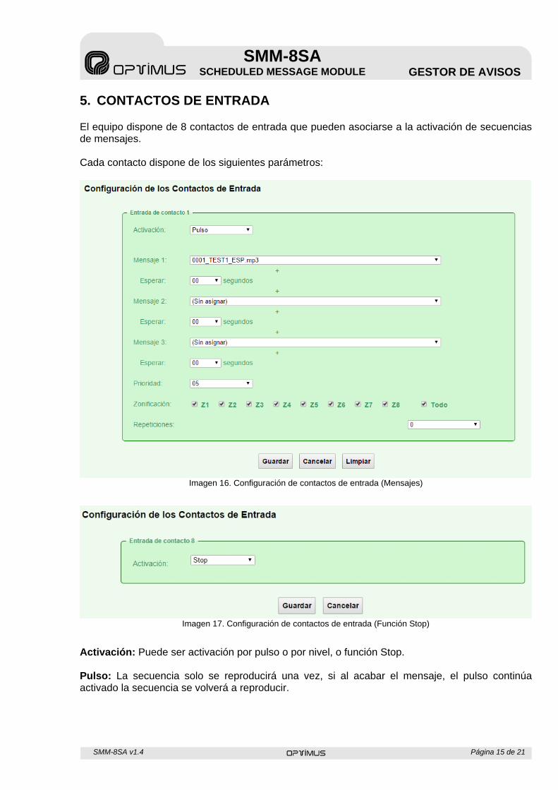
5. CONTACTOS DE ENTRADA El equipo dispone de 8 contactos de entrada que pueden asociarse a la activación de secuencias de mensajes. Cada contacto dispone de los siguientes parámetros:
Imagen 16. Configuración de contactos de entrada (Mensajes)
Imagen 17. Configuración de contactos de entrada (Función Stop)
Activación: Puede ser activación por pulso o por nivel, o función Stop. Pulso: La secuencia solo se reproducirá una vez, si al acabar el mensaje, el pulso continúa activado la secuencia se volverá a reproducir.
SMM-8SA v1.4 Página 16 de 21
SMM-8SA SCHEDULED MESSAGE MODULE GESTOR DE AVISOS
Nivel: La secuencia se reproducirá continuamente mientras el contacto esté cerrado, en el momento en que el contacto se abra ésta se parará. Stop: Parará la secuencia en curso (solo para secuencias activadas por pulso). Mensaje 1: Seleccione un mensaje de los cargados en memoria. Esperar: Seleccione el retardo entre el primer y el segundo mensaje. Mensaje 2: Seleccione un mensaje de los cargados en memoria. Esperar: Seleccione el retardo entre el segundo y el tercer mensaje. Mensaje 3: Seleccione un mensaje de los cargados en memoria. Esperar: Seleccione el retardo antes de acabar el evento. *Si solo se quiere reproducir un mensaje deje los campos mensaje 2 y 3 en blanco. Prioridad: Seleccione la prioridad para la secuencia. La prioridad determinará qué mensaje se reproducirá en el caso de activaciones simultáneas, siendo 1 la prioridad máxima y 10 la prioridad mínima. Zonificación: Seleccione las zonas por las que se tenga que reproducir la secuencia. Repeticiones: Seleccione cuantas veces se reproducirá la secuencia de los 3 mensajes. Pulse “Guardar” para salvar los cambios o “Cancelar“ para descartar los cambios.
SMM-8SA v1.4 Página 17 de 21
SMM-8SA SCHEDULED MESSAGE MODULE GESTOR DE AVISOS
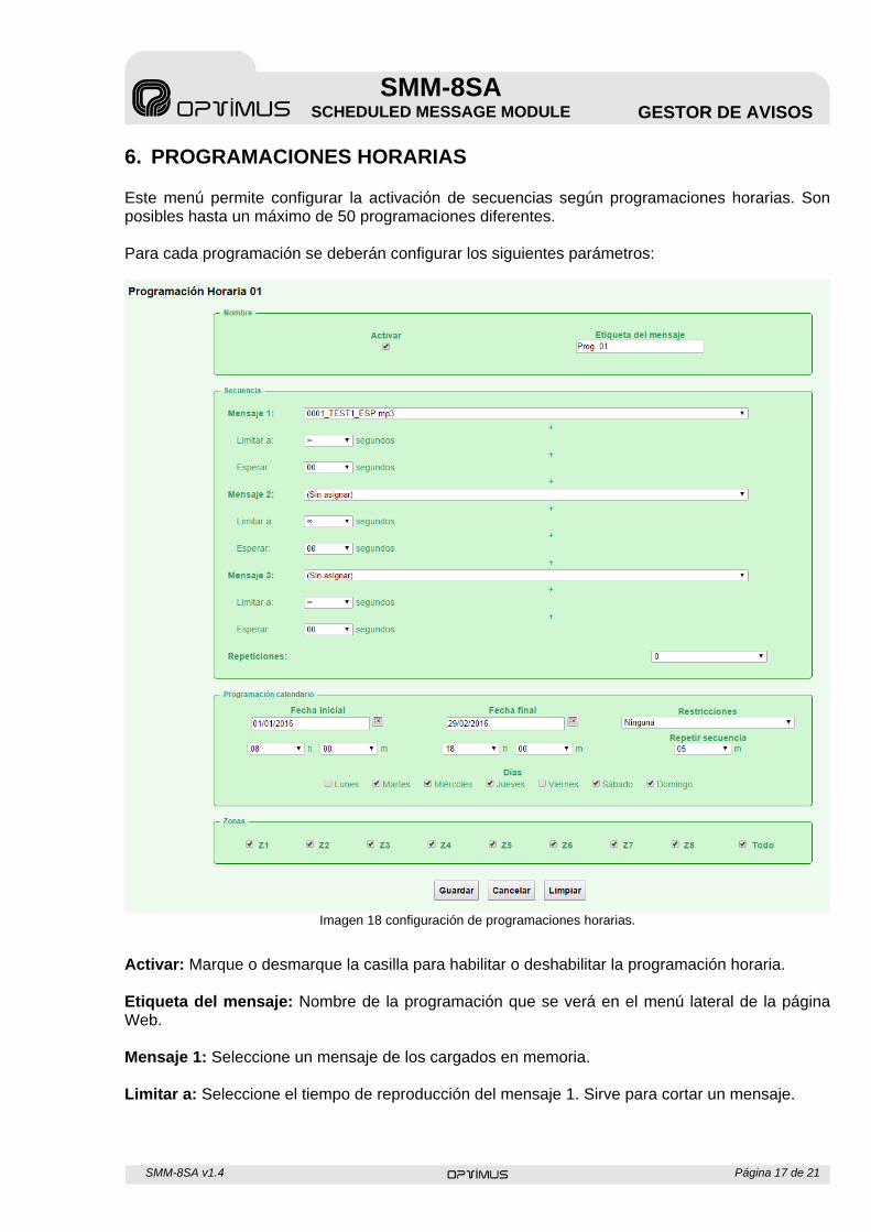
6. PROGRAMACIONES HORARIAS Este menú permite configurar la activación de secuencias según programaciones horarias. Son posibles hasta un máximo de 50 programaciones diferentes. Para cada programación se deberán configurar los siguientes parámetros:
Imagen 18 configuración de programaciones horarias.
Activar: Marque o desmarque la casilla para habilitar o deshabilitar la programación horaria. Etiqueta del mensaje: Nombre de la programación que se verá en el menú lateral de la página Web. Mensaje 1: Seleccione un mensaje de los cargados en memoria. Limitar a: Seleccione el tiempo de reproducción del mensaje 1. Sirve para cortar un mensaje.
SMM-8SA v1.4 Página 18 de 21
SMM-8SA SCHEDULED MESSAGE MODULE GESTOR DE AVISOS
Esperar: Seleccione el retardo entre el final del primer mensaje y el inicio del segundo. Mensaje 2: Seleccione un mensaje de los cargados en memoria. Limitar a: Seleccione el tiempo de reproducción del mensaje 2. Sirve para cortar un mensaje. Esperar: Seleccione el retardo entre el final del segundo mensaje y el inicio del tercero. Mensaje 3: Seleccione un mensaje de los cargados en memoria. Limitar a: Seleccione el tiempo de reproducción del mensaje 3. Sirve para cortar un mensaje. Esperar: Seleccione el retardo antes de acabar el evento. *Si solo se quiere reproducir un mensaje dejar los campos mensaje 2 y 3 en blanco. Repeticiones: Seleccione cuantas veces se reproducirá la secuencia de los 3 mensajes. Fecha inicial: Seleccione el día y la hora en que se empezará a aplicar la programación horaria. Fecha final: Seleccione el día y la hora en que terminará la programación horaria. Restricciones: Seleccione si se aplicarán restricciones por días festivos. Días: Seleccione si la programación estará activada diariamente o cualquier combinatoria de días. Repetir secuencia: Seleccione cada cuanto tiempo se repetirá la secuencia entre la hora inicial y la hora final. Si solo se requiere una reproducción se debe dejar este campo en blanco. Zonas: Seleccione las zonas por las que se tenga que reproducir el secuencia. Pulse “Guardar” para salvar los cambios, “Cancelar” para descartar los cambios o “Limpiar” para restaurar la configuración de fábrica.
SMM-8SA v1.4 Página 19 de 21
SMM-8SA SCHEDULED MESSAGE MODULE GESTOR DE AVISOS
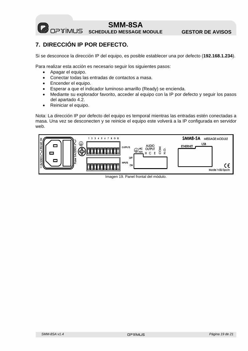
7. DIRECCIÓN IP POR DEFECTO. Si se desconoce la dirección IP del equipo, es posible establecer una por defecto (192.168.1.234). Para realizar esta acción es necesario seguir los siguientes pasos:
Apagar el equipo. Conectar todas las entradas de contactos a masa. Encender el equipo. Esperar a que el indicador luminoso amarillo (Ready) se encienda. Mediante su explorador favorito, acceder al equipo con la IP por defecto y seguir los pasos
del apartado 4.2. Reiniciar el equipo.
Nota: La dirección IP por defecto del equipo es temporal mientras las entradas estén conectadas a masa. Una vez se desconecten y se reinicie el equipo este volverá a la IP configurada en servidor web.
Imagen 19. Panel frontal del módulo.
SMM-8SA v1.4 Página 20 de 21
SMM-8SA SCHEDULED MESSAGE MODULE GESTOR DE AVISOS
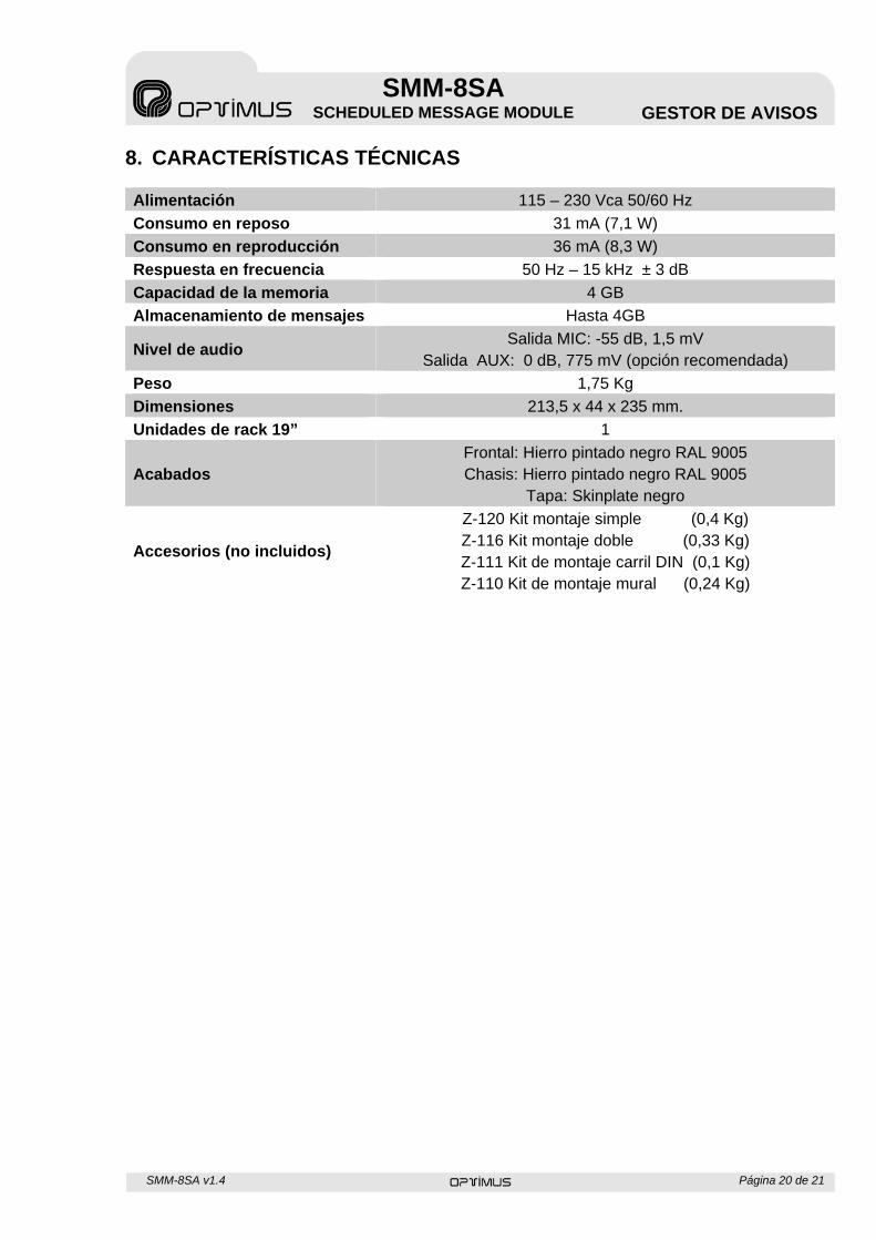
8. CARACTERÍSTICAS TÉCNICAS Alimentación 115 – 230 Vca 50/60 Hz
Consumo en reposo 31 mA (7,1 W)
Consumo en reproducción 36 mA (8,3 W)
Respuesta en frecuencia 50 Hz – 15 kHz ± 3 dB
Capacidad de la memoria 4 GB
Almacenamiento de mensajes Hasta 4GB
Nivel de audio Salida MIC: -55 dB, 1,5 mV
Salida AUX: 0 dB, 775 mV (opción recomendada)
Peso 1,75 Kg
Dimensiones 213,5 x 44 x 235 mm.
Unidades de rack 19” 1
Acabados Frontal: Hierro pintado negro RAL 9005 Chasis: Hierro pintado negro RAL 9005
Tapa: Skinplate negro
Accesorios (no incluidos)
Z-120 Kit montaje simple (0,4 Kg) Z-116 Kit montaje doble (0,33 Kg) Z-111 Kit de montaje carril DIN (0,1 Kg) Z-110 Kit de montaje mural (0,24 Kg)
SMM-8SA v1.4 Página 21 de 21
SMM-8SA SCHEDULED MESSAGE MODULE GESTOR DE AVISOS
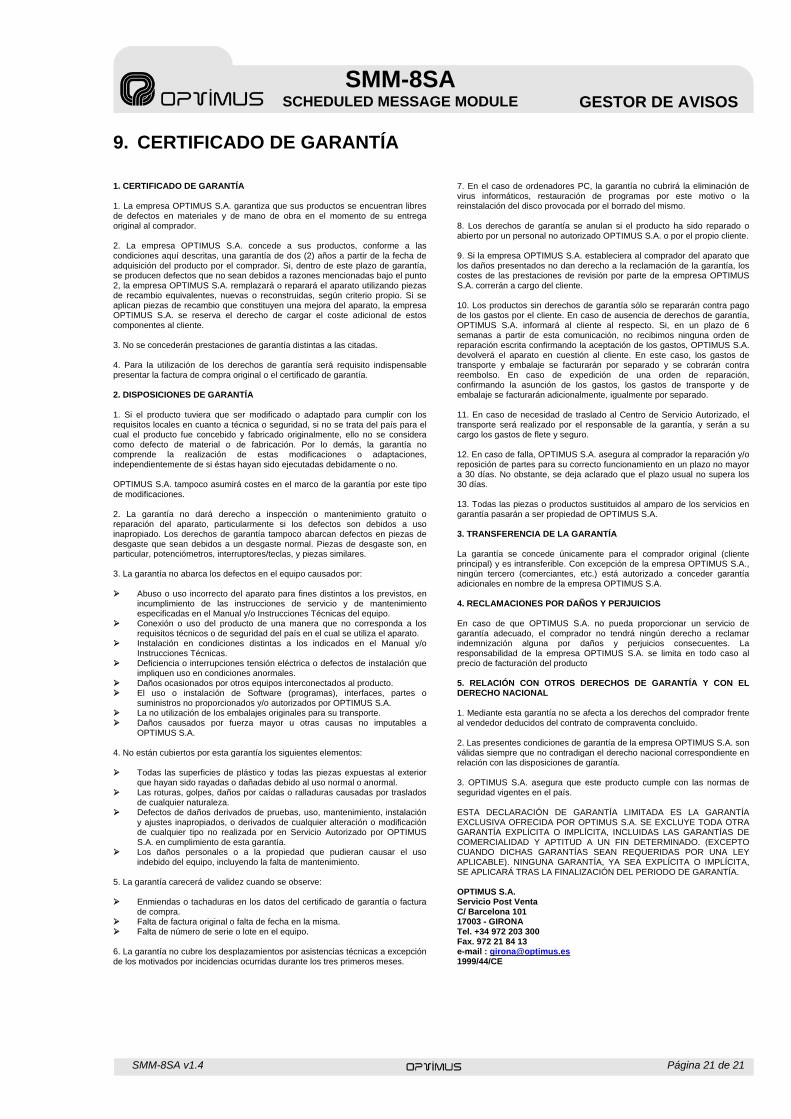
9. CERTIFICADO DE GARANTÍA 1. CERTIFICADO DE GARANTÍA 1. La empresa OPTIMUS S.A. garantiza que sus productos se encuentran libres de defectos en materiales y de mano de obra en el momento de su entrega original al comprador. 2. La empresa OPTIMUS S.A. concede a sus productos, conforme a las condiciones aquí descritas, una garantía de dos (2) años a partir de la fecha de adquisición del producto por el comprador. Si, dentro de este plazo de garantía, se producen defectos que no sean debidos a razones mencionadas bajo el punto 2, la empresa OPTIMUS S.A. remplazará o reparará el aparato utilizando piezas de recambio equivalentes, nuevas o reconstruidas, según criterio propio. Si se aplican piezas de recambio que constituyen una mejora del aparato, la empresa OPTIMUS S.A. se reserva el derecho de cargar el coste adicional de estos componentes al cliente. 3. No se concederán prestaciones de garantía distintas a las citadas. 4. Para la utilización de los derechos de garantía será requisito indispensable presentar la factura de compra original o el certificado de garantía. 2. DISPOSICIONES DE GARANTÍA 1. Si el producto tuviera que ser modificado o adaptado para cumplir con los requisitos locales en cuanto a técnica o seguridad, si no se trata del país para el cual el producto fue concebido y fabricado originalmente, ello no se considera como defecto de material o de fabricación. Por lo demás, la garantía no comprende la realización de estas modificaciones o adaptaciones, independientemente de si éstas hayan sido ejecutadas debidamente o no. OPTIMUS S.A. tampoco asumirá costes en el marco de la garantía por este tipo de modificaciones. 2. La garantía no dará derecho a inspección o mantenimiento gratuito o reparación del aparato, particularmente si los defectos son debidos a uso inapropiado. Los derechos de garantía tampoco abarcan defectos en piezas de desgaste que sean debidos a un desgaste normal. Piezas de desgaste son, en particular, potenciómetros, interruptores/teclas, y piezas similares. 3. La garantía no abarca los defectos en el equipo causados por: Abuso o uso incorrecto del aparato para fines distintos a los previstos, en
incumplimiento de las instrucciones de servicio y de mantenimiento especificadas en el Manual y/o Instrucciones Técnicas del equipo.
Conexión o uso del producto de una manera que no corresponda a los requisitos técnicos o de seguridad del país en el cual se utiliza el aparato.
Instalación en condiciones distintas a los indicados en el Manual y/o Instrucciones Técnicas.
Deficiencia o interrupciones tensión eléctrica o defectos de instalación que impliquen uso en condiciones anormales.
Daños ocasionados por otros equipos interconectados al producto. El uso o instalación de Software (programas), interfaces, partes o
suministros no proporcionados y/o autorizados por OPTIMUS S.A. La no utilización de los embalajes originales para su transporte. Daños causados por fuerza mayor u otras causas no imputables a
OPTIMUS S.A. 4. No están cubiertos por esta garantía los siguientes elementos: Todas las superficies de plástico y todas las piezas expuestas al exterior
que hayan sido rayadas o dañadas debido al uso normal o anormal. Las roturas, golpes, daños por caídas o ralladuras causadas por traslados
de cualquier naturaleza. Defectos de daños derivados de pruebas, uso, mantenimiento, instalación
y ajustes inapropiados, o derivados de cualquier alteración o modificación de cualquier tipo no realizada por en Servicio Autorizado por OPTIMUS S.A. en cumplimiento de esta garantía.
Los daños personales o a la propiedad que pudieran causar el uso indebido del equipo, incluyendo la falta de mantenimiento.
5. La garantía carecerá de validez cuando se observe: Enmiendas o tachaduras en los datos del certificado de garantía o factura
de compra. Falta de factura original o falta de fecha en la misma. Falta de número de serie o lote en el equipo. 6. La garantía no cubre los desplazamientos por asistencias técnicas a excepción de los motivados por incidencias ocurridas durante los tres primeros meses.
7. En el caso de ordenadores PC, la garantía no cubrirá la eliminación de virus informáticos, restauración de programas por este motivo o la reinstalación del disco provocada por el borrado del mismo. 8. Los derechos de garantía se anulan si el producto ha sido reparado o abierto por un personal no autorizado OPTIMUS S.A. o por el propio cliente. 9. Si la empresa OPTIMUS S.A. estableciera al comprador del aparato que los daños presentados no dan derecho a la reclamación de la garantía, los costes de las prestaciones de revisión por parte de la empresa OPTIMUS S.A. correrán a cargo del cliente. 10. Los productos sin derechos de garantía sólo se repararán contra pago de los gastos por el cliente. En caso de ausencia de derechos de garantía, OPTIMUS S.A. informará al cliente al respecto. Si, en un plazo de 6 semanas a partir de esta comunicación, no recibimos ninguna orden de reparación escrita confirmando la aceptación de los gastos, OPTIMUS S.A. devolverá el aparato en cuestión al cliente. En este caso, los gastos de transporte y embalaje se facturarán por separado y se cobrarán contra reembolso. En caso de expedición de una orden de reparación, confirmando la asunción de los gastos, los gastos de transporte y de embalaje se facturarán adicionalmente, igualmente por separado. 11. En caso de necesidad de traslado al Centro de Servicio Autorizado, el transporte será realizado por el responsable de la garantía, y serán a su cargo los gastos de flete y seguro. 12. En caso de falla, OPTIMUS S.A. asegura al comprador la reparación y/o reposición de partes para su correcto funcionamiento en un plazo no mayor a 30 días. No obstante, se deja aclarado que el plazo usual no supera los 30 días. 13. Todas las piezas o productos sustituidos al amparo de los servicios en garantía pasarán a ser propiedad de OPTIMUS S.A. 3. TRANSFERENCIA DE LA GARANTÍA La garantía se concede únicamente para el comprador original (cliente principal) y es intransferible. Con excepción de la empresa OPTIMUS S.A., ningún tercero (comerciantes, etc.) está autorizado a conceder garantía adicionales en nombre de la empresa OPTIMUS S.A. 4. RECLAMACIONES POR DAÑOS Y PERJUICIOS En caso de que OPTIMUS S.A. no pueda proporcionar un servicio de garantía adecuado, el comprador no tendrá ningún derecho a reclamar indemnización alguna por daños y perjuicios consecuentes. La responsabilidad de la empresa OPTIMUS S.A. se limita en todo caso al precio de facturación del producto 5. RELACIÓN CON OTROS DERECHOS DE GARANTÍA Y CON EL DERECHO NACIONAL 1. Mediante esta garantía no se afecta a los derechos del comprador frente al vendedor deducidos del contrato de compraventa concluido. 2. Las presentes condiciones de garantía de la empresa OPTIMUS S.A. son válidas siempre que no contradigan el derecho nacional correspondiente en relación con las disposiciones de garantía. 3. OPTIMUS S.A. asegura que este producto cumple con las normas de seguridad vigentes en el país. ESTA DECLARACIÓN DE GARANTÍA LIMITADA ES LA GARANTÍA EXCLUSIVA OFRECIDA POR OPTIMUS S.A. SE EXCLUYE TODA OTRA GARANTÍA EXPLÍCITA O IMPLÍCITA, INCLUIDAS LAS GARANTÍAS DE COMERCIALIDAD Y APTITUD A UN FIN DETERMINADO. (EXCEPTO CUANDO DICHAS GARANTÍAS SEAN REQUERIDAS POR UNA LEY APLICABLE). NINGUNA GARANTÍA, YA SEA EXPLÍCITA O IMPLÍCITA, SE APLICARÁ TRAS LA FINALIZACIÓN DEL PERIODO DE GARANTÍA. OPTIMUS S.A. Servicio Post Venta C/ Barcelona 101 17003 - GIRONA Tel. +34 972 203 300 Fax. 972 21 84 13 e-mail : [email protected] 1999/44/CE
SMM-8SA v1.4 Page 1 of 20
SMM-8SA SCHEDULED MESSAGE MODULE MESSAGE MANAGER
SAFETY INSTRUCTIONS:
IMPORTANT:
Read carefully the safety instructions.
Keep this manual for future references.
Unplug the equipment during lightning storms or if it won’t be used for a long time.
Always use certified wires to prevent electric shock or fire. In case of doubt, consult a qualified installer.
Do not use the unit in humid places or near liquids. Do not install it near heat sources. Do not block ventilation openings.
When it is necessary, remove dust with a dry cloth. Do not use solvents such as alcohol. Keep the unit clean and dust free.
Maintenance operations require qualified personnel. Note: The information provided in this manual does not include neither details of design production or variations in equipment, nor possible risks during installation, operation or maintenance. If you need special assistance beyond the manual, please contact our customer service.

SMM-8SA v1.4 Page 2 of 20
SMM-8SA SCHEDULED MESSAGE MODULE MESSAGE MANAGER
ÍNDICE 1. GENERAL INFORMATION .......................................................................................... 3 2. OPERATION ................................................................................................................ 4
2.1 FRONT PANEL ..................................................................................................... 4 2.2 REAR PANEL ....................................................................................................... 5
3. CONNECTION EXAMPLE ........................................................................................... 7 4. UNIT CONFIGURATION .............................................................................................. 8
4.1 ACCESS TO WEB SERVER ................................................................................ 8 4.2 NETWORK ............................................................................................................ 9 4.3 USER / LANGUAGE ........................................................................................... 10 4.4 DATE AND TIME ................................................................................................ 10 4.5 LOAD MESSAGES ............................................................................................. 11 4.6 SEND MESSAGES ............................................................................................. 12 4.7 MAINTENANCE .................................................................................................. 12 4.8 HOLIDAYS .......................................................................................................... 13 4.9 MONITORING ..................................................................................................... 13
5. INPUT CONTACTS .................................................................................................... 14 6. SCHEDULING ............................................................................................................ 16 7. DEFAULT IP ADDRESS ............................................................................................ 18 8. TECHNICAL SPECIFICATIONS ................................................................................ 19 9. GUARANTEE CERTIFICATE .................................................................................... 20
SMM-8SA v1.4 Page 3 of 20
SMM-8SA SCHEDULED MESSAGE MODULE MESSAGE MANAGER
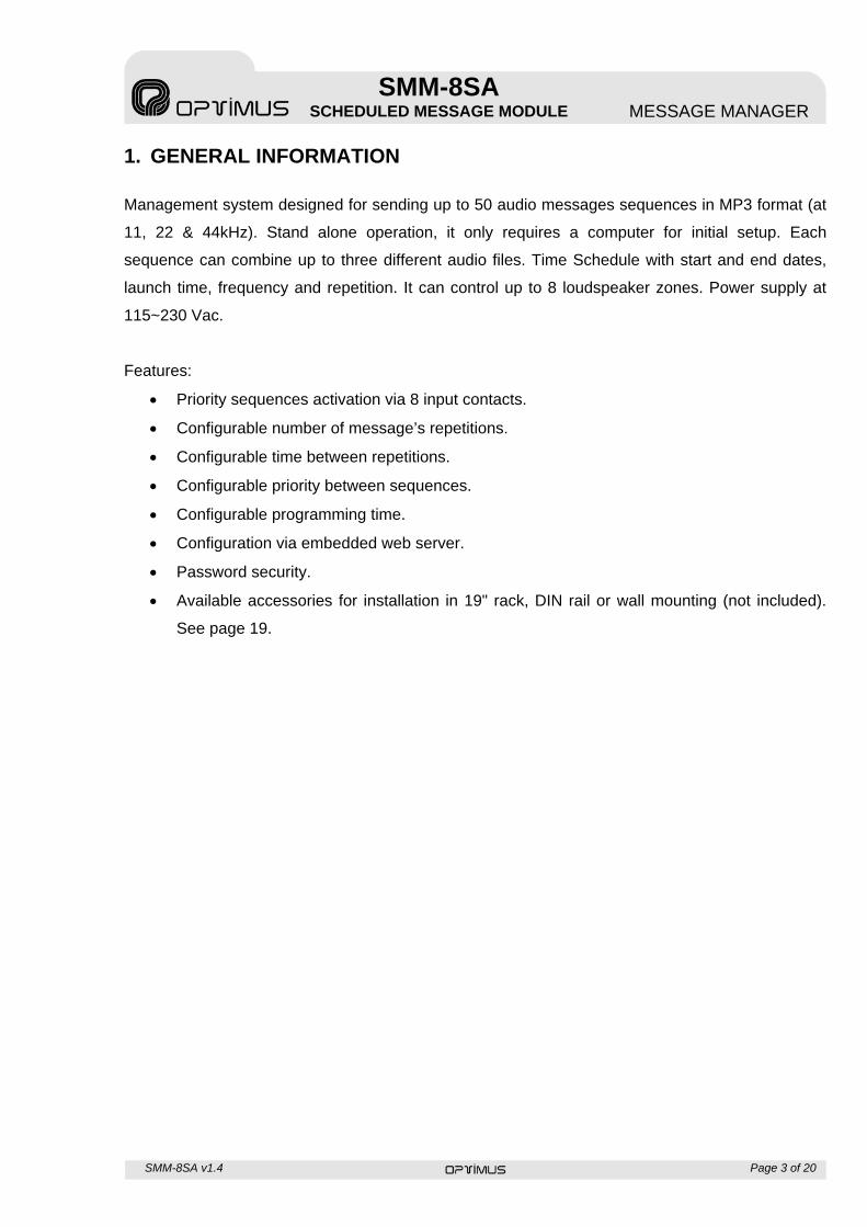
1. GENERAL INFORMATION
Management system designed for sending up to 50 audio messages sequences in MP3 format (at
11, 22 & 44kHz). Stand alone operation, it only requires a computer for initial setup. Each
sequence can combine up to three different audio files. Time Schedule with start and end dates,
launch time, frequency and repetition. It can control up to 8 loudspeaker zones. Power supply at
115~230 Vac.
Features:
Priority sequences activation via 8 input contacts.
Configurable number of message’s repetitions.
Configurable time between repetitions.
Configurable priority between sequences.
Configurable programming time.
Configuration via embedded web server.
Password security.
Available accessories for installation in 19" rack, DIN rail or wall mounting (not included).
See page 19.
SMM-8SA v1.4 Page 4 of 20
SMM-8SA SCHEDULED MESSAGE MODULE MESSAGE MANAGER
2. OPERATION
2.1 FRONT PANEL
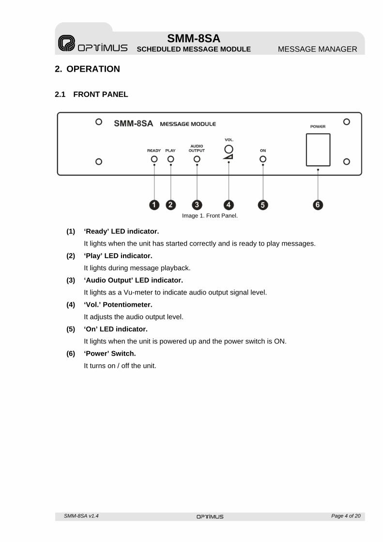
Image 1. Front Panel.
(1) ‘Ready’ LED indicator.
It lights when the unit has started correctly and is ready to play messages.
(2) ‘Play’ LED indicator.
It lights during message playback.
(3) ‘Audio Output’ LED indicator.
It lights as a Vu-meter to indicate audio output signal level.
(4) ‘Vol.’ Potentiometer.
It adjusts the audio output level.
(5) ‘On’ LED indicator.
It lights when the unit is powered up and the power switch is ON.
(6) ‘Power’ Switch.
It turns on / off the unit.
SMM-8SA v1.4 Page 5 of 20
SMM-8SA SCHEDULED MESSAGE MODULE MESSAGE MANAGER
2.2 REAR PANEL
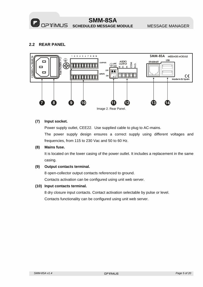
Image 2. Rear Panel.
(7) Input socket.
Power supply outlet, CEE22. Use supplied cable to plug to AC-mains.
The power supply design ensures a correct supply using different voltages and
frequencies, from 115 to 230 Vac and 50 to 60 Hz.
(8) Mains fuse.
It is located on the lower casing of the power outlet. It includes a replacement in the same
casing.
(9) Output contacts terminal.
8 open-collector output contacts referenced to ground.
Contacts activation can be configured using unit web server.
(10) Input contacts terminal.
8 dry closure input contacts. Contact activation selectable by pulse or level.
Contacts functionality can be configured using unit web server.
SMM-8SA v1.4 Page 6 of 20
SMM-8SA SCHEDULED MESSAGE MODULE MESSAGE MANAGER
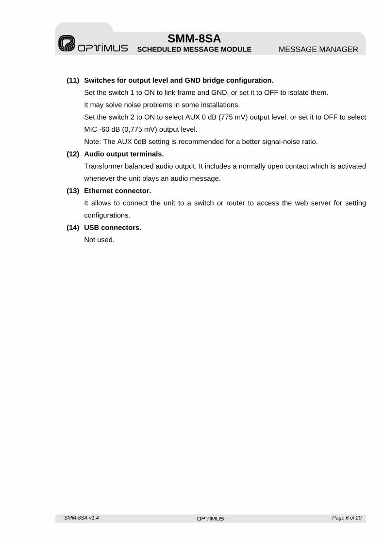
(11) Switches for output level and GND bridge configuration.
Set the switch 1 to ON to link frame and GND, or set it to OFF to isolate them.
It may solve noise problems in some installations.
Set the switch 2 to ON to select AUX 0 dB (775 mV) output level, or set it to OFF to select
MIC -60 dB (0,775 mV) output level.
Note: The AUX 0dB setting is recommended for a better signal-noise ratio.
(12) Audio output terminals.
Transformer balanced audio output. It includes a normally open contact which is activated
whenever the unit plays an audio message.
(13) Ethernet connector.
It allows to connect the unit to a switch or router to access the web server for setting
configurations.
(14) USB connectors.
Not used.
SMM-8SA v1.4 Page 7 of 20
SMM-8SA SCHEDULED MESSAGE MODULE MESSAGE MANAGER
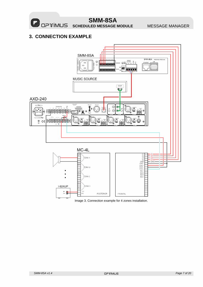
3. CONNECTION EXAMPLE
Image 3. Connection example for 4 zones installation.
SMM-8SA v1.4 Page 8 of 20
SMM-8SA SCHEDULED MESSAGE MODULE MESSAGE MANAGER
4. UNIT CONFIGURATION
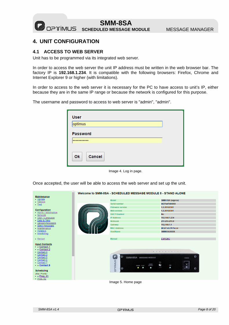
4.1 ACCESS TO WEB SERVER Unit has to be programmed via its integrated web server. In order to access the web server the unit IP address must be written in the web browser bar. The factory IP is 192.168.1.234. It is compatible with the following browsers: Firefox, Chrome and Internet Explorer 9 or higher (with limitations). In order to access to the web server it is necessary for the PC to have access to unit’s IP, either because they are in the same IP range or because the network is configured for this purpose. The username and password to access to web server is "admin", "admin".
Image 4. Log in page.
Once accepted, the user will be able to access the web server and set up the unit.
Image 5. Home page
SMM-8SA v1.4 Page 9 of 20
SMM-8SA SCHEDULED MESSAGE MODULE MESSAGE MANAGER
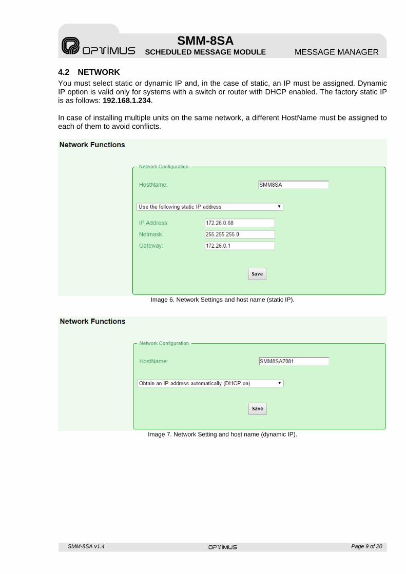
4.2 NETWORK You must select static or dynamic IP and, in the case of static, an IP must be assigned. Dynamic IP option is valid only for systems with a switch or router with DHCP enabled. The factory static IP is as follows: 192.168.1.234. In case of installing multiple units on the same network, a different HostName must be assigned to each of them to avoid conflicts.
Image 6. Network Settings and host name (static IP).
Image 7. Network Setting and host name (dynamic IP).
SMM-8SA v1.4 Page 10 of 20
SMM-8SA SCHEDULED MESSAGE MODULE MESSAGE MANAGER
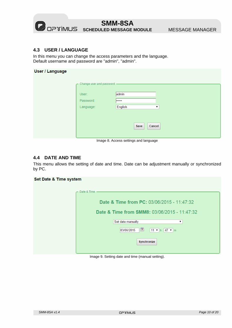
4.3 USER / LANGUAGE In this menu you can change the access parameters and the language. Default username and password are "admin", "admin".
Image 8. Access settings and language
4.4 DATE AND TIME This menu allows the setting of date and time. Date can be adjustment manually or synchronized by PC.
Image 9. Setting date and time (manual setting).
SMM-8SA v1.4 Page 11 of 20
SMM-8SA SCHEDULED MESSAGE MODULE MESSAGE MANAGER
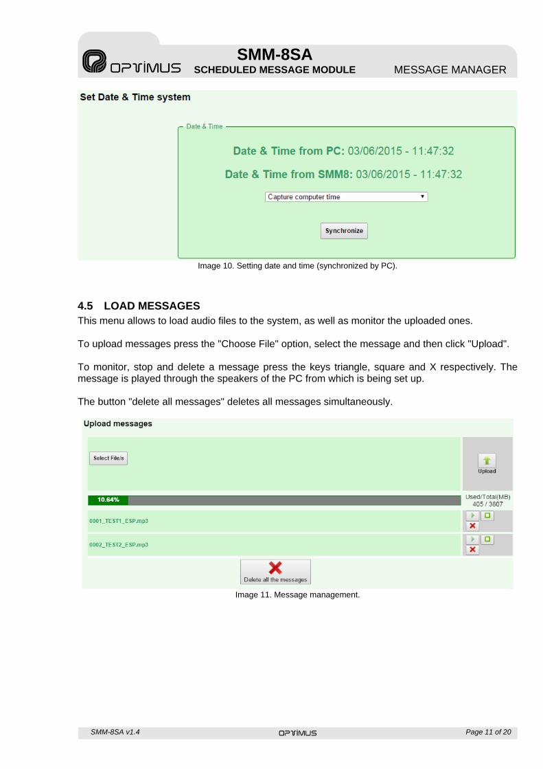
Image 10. Setting date and time (synchronized by PC).
4.5 LOAD MESSAGES This menu allows to load audio files to the system, as well as monitor the uploaded ones. To upload messages press the "Choose File" option, select the message and then click "Upload". To monitor, stop and delete a message press the keys triangle, square and X respectively. The message is played through the speakers of the PC from which is being set up. The button "delete all messages" deletes all messages simultaneously.
Image 11. Message management.
SMM-8SA v1.4 Page 12 of 20
SMM-8SA SCHEDULED MESSAGE MODULE MESSAGE MANAGER
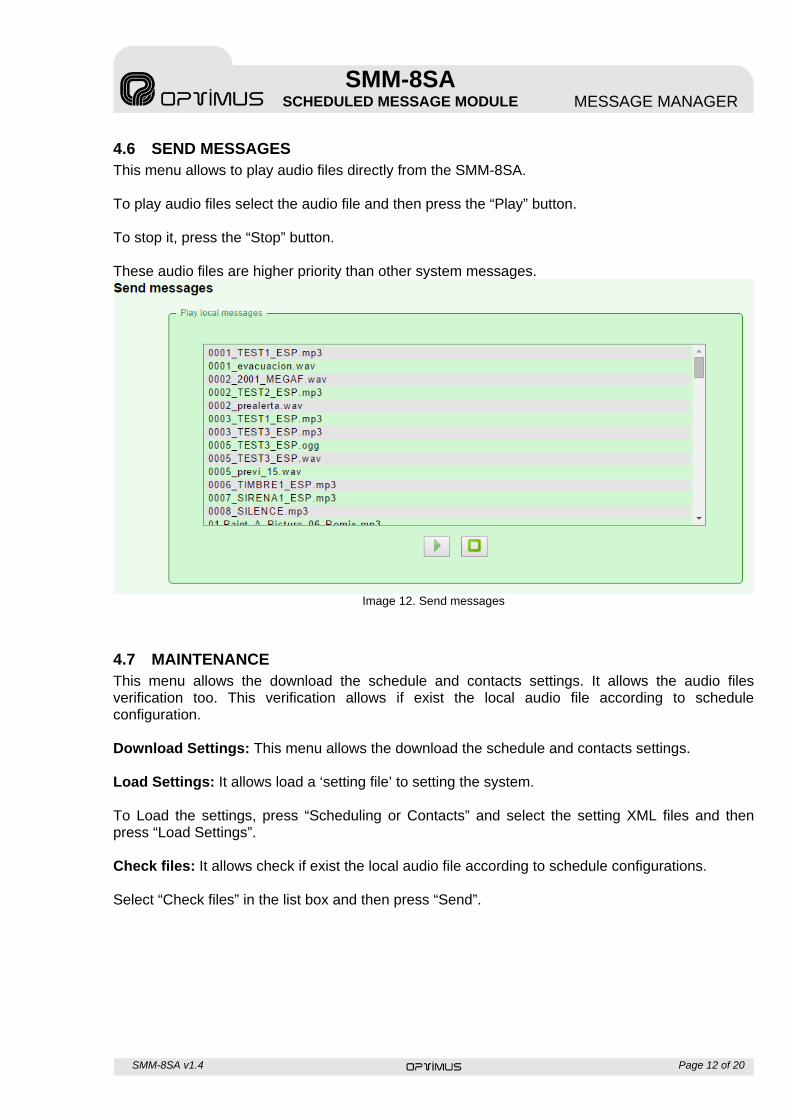
4.6 SEND MESSAGES This menu allows to play audio files directly from the SMM-8SA. To play audio files select the audio file and then press the “Play” button. To stop it, press the “Stop” button. These audio files are higher priority than other system messages.
Image 12. Send messages
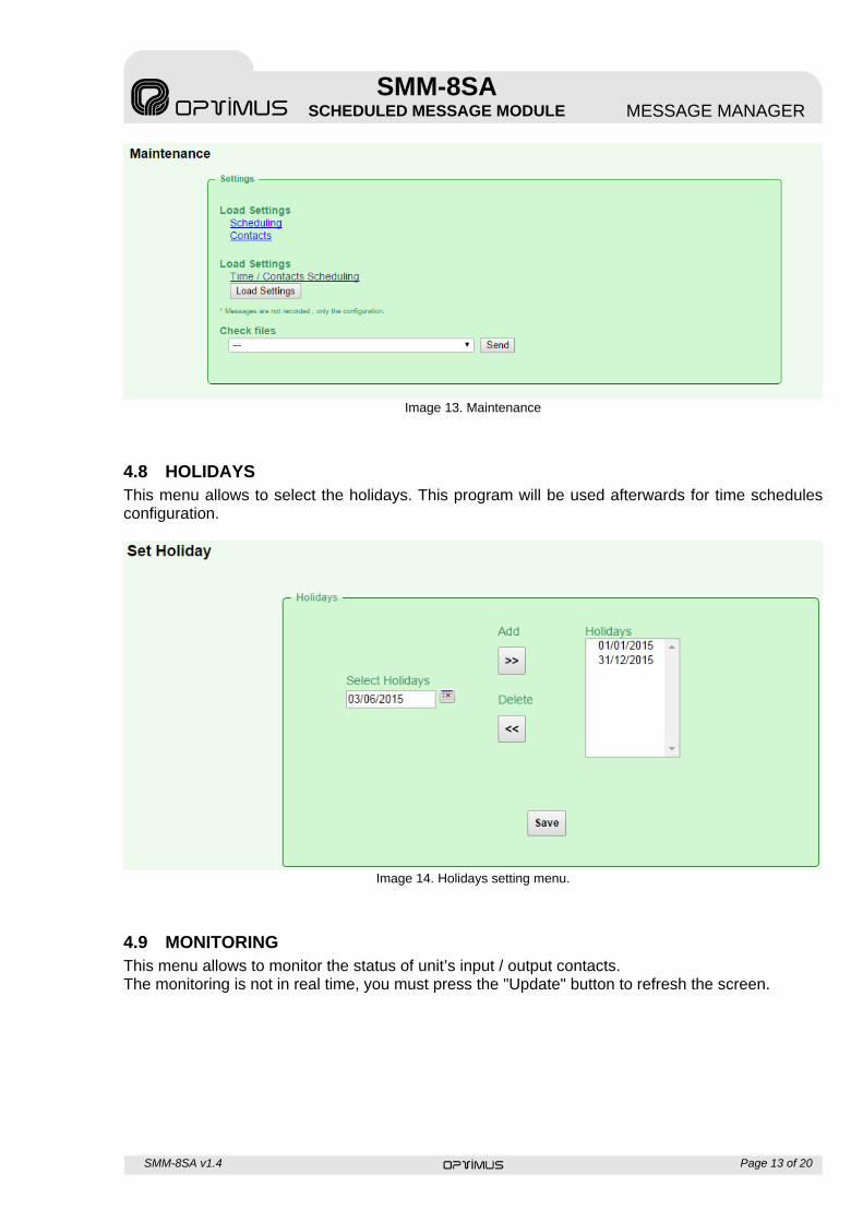
4.7 MAINTENANCE This menu allows the download the schedule and contacts settings. It allows the audio files verification too. This verification allows if exist the local audio file according to schedule configuration. Download Settings: This menu allows the download the schedule and contacts settings. Load Settings: It allows load a ‘setting file’ to setting the system. To Load the settings, press “Scheduling or Contacts” and select the setting XML files and then press “Load Settings”. Check files: It allows check if exist the local audio file according to schedule configurations. Select “Check files” in the list box and then press “Send”.
SMM-8SA v1.4 Page 13 of 20
SMM-8SA SCHEDULED MESSAGE MODULE MESSAGE MANAGER
Image 13. Maintenance
4.8 HOLIDAYS This menu allows to select the holidays. This program will be used afterwards for time schedules configuration.
Image 14. Holidays setting menu.
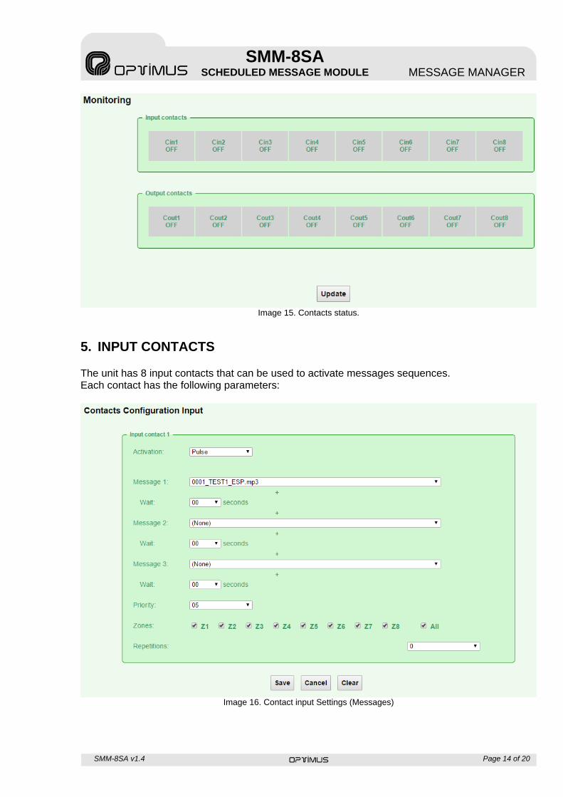
4.9 MONITORING This menu allows to monitor the status of unit’s input / output contacts. The monitoring is not in real time, you must press the "Update" button to refresh the screen.
SMM-8SA v1.4 Page 14 of 20
SMM-8SA SCHEDULED MESSAGE MODULE MESSAGE MANAGER
Image 15. Contacts status.
5. INPUT CONTACTS The unit has 8 input contacts that can be used to activate messages sequences. Each contact has the following parameters:
Image 16. Contact input Settings (Messages)
SMM-8SA v1.4 Page 15 of 20
SMM-8SA SCHEDULED MESSAGE MODULE MESSAGE MANAGER
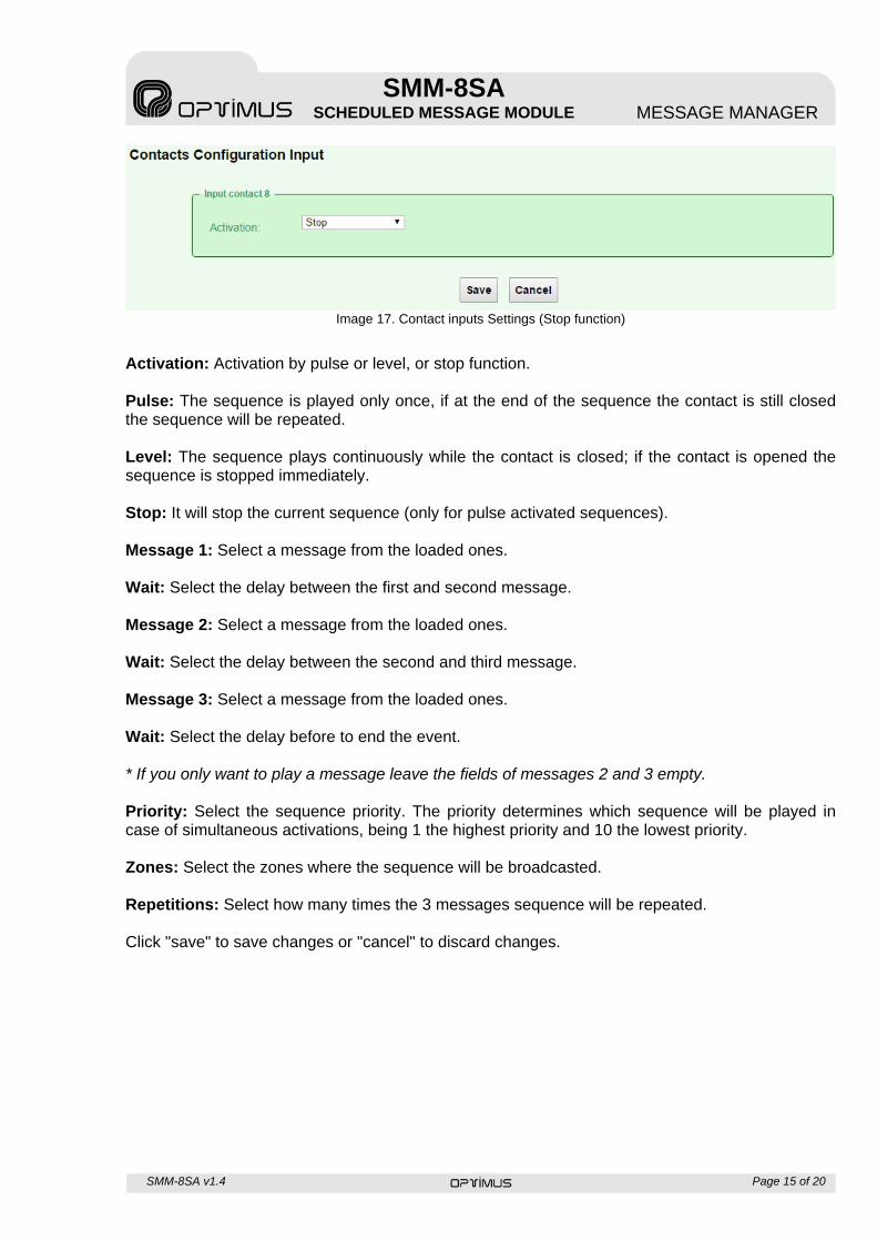
Image 17. Contact inputs Settings (Stop function)
Activation: Activation by pulse or level, or stop function. Pulse: The sequence is played only once, if at the end of the sequence the contact is still closed the sequence will be repeated. Level: The sequence plays continuously while the contact is closed; if the contact is opened the sequence is stopped immediately. Stop: It will stop the current sequence (only for pulse activated sequences). Message 1: Select a message from the loaded ones. Wait: Select the delay between the first and second message. Message 2: Select a message from the loaded ones. Wait: Select the delay between the second and third message. Message 3: Select a message from the loaded ones. Wait: Select the delay before to end the event. * If you only want to play a message leave the fields of messages 2 and 3 empty. Priority: Select the sequence priority. The priority determines which sequence will be played in case of simultaneous activations, being 1 the highest priority and 10 the lowest priority. Zones: Select the zones where the sequence will be broadcasted. Repetitions: Select how many times the 3 messages sequence will be repeated. Click "save" to save changes or "cancel" to discard changes.
SMM-8SA v1.4 Page 16 of 20
SMM-8SA SCHEDULED MESSAGE MODULE MESSAGE MANAGER
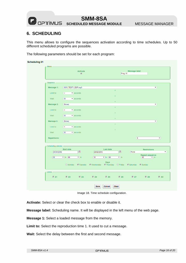
6. SCHEDULING This menu allows to configure the sequences activation according to time schedules. Up to 50 different scheduled programs are possible. The following parameters should be set for each program:
Image 18. Time schedule configuration.
Activate: Select or clear the check box to enable or disable it. Message label: Scheduling name. It will be displayed in the left menu of the web page. Message 1: Select a loaded message from the memory. Limit to: Select the reproduction time 1. It used to cut a message. Wait: Select the delay between the first and second message.
SMM-8SA v1.4 Page 17 of 20
SMM-8SA SCHEDULED MESSAGE MODULE MESSAGE MANAGER
Message 2: Select a loaded message from the memory. Limit to: Select the reproduction time 2. It used to cut a message. Wait: Select the delay between the second and third message. Message 3: Select a loaded message from the memory. Limit to: Select the reproduction time 3. It used to cut a message. Wait: Select the delay before to end the event. * If you want to play only one message, leave the fields of the messages 2 and 3 empty. Repetitions: Select how many times the 3 messages sequence will be repeated. Start Date: Select the day and time for the program start. End Date: Select the day and time for the program end. Restrictions: Choose desired restrictions to be applied. Days: Select if the program will be activated daily, Monday through Friday, or Monday to Sunday. Repeat sequence: Select how often the sequence will be repeated between the start time and end time. If only one repetition is required, leave this field blank. Zones: Select the zones where the sequence will be to broadcast. Click "save" to save changes, "cancel" to discard the changes or “Clean” to restore the factory settings.
SMM-8SA v1.4 Page 18 of 20
SMM-8SA SCHEDULED MESSAGE MODULE MESSAGE MANAGER
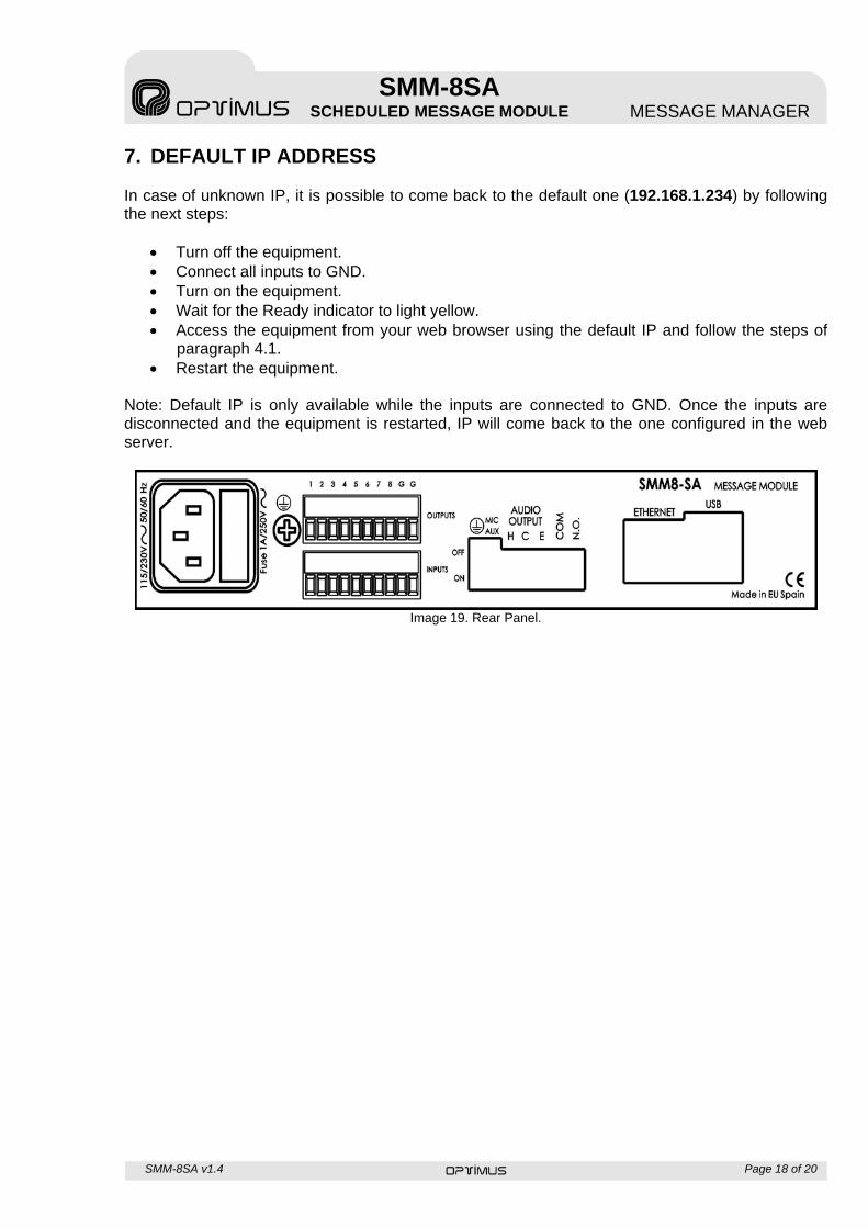
7. DEFAULT IP ADDRESS In case of unknown IP, it is possible to come back to the default one (192.168.1.234) by following the next steps:
Turn off the equipment. Connect all inputs to GND. Turn on the equipment. Wait for the Ready indicator to light yellow. Access the equipment from your web browser using the default IP and follow the steps of
paragraph 4.1. Restart the equipment.
Note: Default IP is only available while the inputs are connected to GND. Once the inputs are disconnected and the equipment is restarted, IP will come back to the one configured in the web server.
Image 19. Rear Panel.
SMM-8SA v1.4 Page 19 of 20
SMM-8SA SCHEDULED MESSAGE MODULE MESSAGE MANAGER
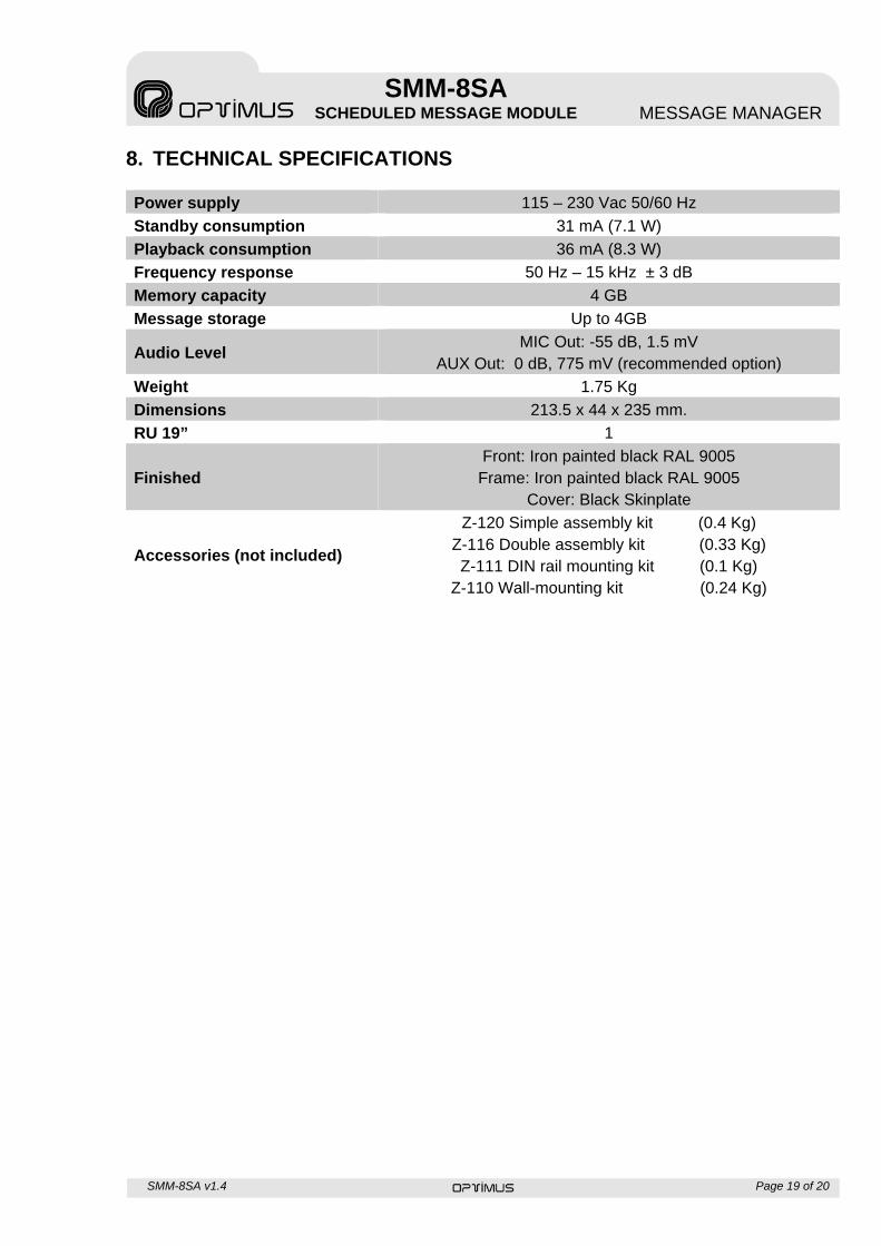
8. TECHNICAL SPECIFICATIONS
Power supply 115 – 230 Vac 50/60 Hz
Standby consumption 31 mA (7.1 W)
Playback consumption 36 mA (8.3 W)
Frequency response 50 Hz – 15 kHz ± 3 dB
Memory capacity 4 GB
Message storage Up to 4GB
Audio Level MIC Out: -55 dB, 1.5 mV
AUX Out: 0 dB, 775 mV (recommended option)
Weight 1.75 Kg
Dimensions 213.5 x 44 x 235 mm.
RU 19” 1
Finished Front: Iron painted black RAL 9005
Frame: Iron painted black RAL 9005 Cover: Black Skinplate
Accessories (not included)
Z-120 Simple assembly kit (0.4 Kg) Z-116 Double assembly kit (0.33 Kg) Z-111 DIN rail mounting kit (0.1 Kg)
Z-110 Wall-mounting kit (0.24 Kg)
SMM-8SA v1.4 Page 20 of 20
SMM-8SA SCHEDULED MESSAGE MODULE MESSAGE MANAGER
9. GUARANTEE CERTIFICATE OPTIMUS S.A. guarantees that its products are free from material and manufacturing defects when they are first delivered to the purchaser. 2. In accordance with the conditions outlined here, OPTIMUS S.A. guarantees its products for two (2) years from the date on which the purchaser acquires the product. If, within this guarantee period, defects appear which are not due to factors outlined in section 2, OPTIMUS S.A. shall replace or repair the unit using equivalent, new or reconstructed replacement parts, as it deems fit. If replacement parts are applied which improve the unit, OPTIMUS S.A. reserves the right to charge the client for the additional cost of these components. 3. No guarantee benefits shall be provided other than those cited here. 4. In order to claim the guarantee rights, it shall be an essential requirement to present the original purchase invoice or the guarantee certificate. 2. GUARANTEE PROVISIONS 1. In the event that the product had to be modified or adapted to comply with local requirements concerning technical specifications or safety, and if the country in question is not the country for which the product was originally designed and manufactured, defects are not considered to be material or manufacturing defects. Furthermore, the guarantee does not cover the execution of these modifications or adaptations, regardless of whether or not they have been carried out correctly. Nor shall OPTIMUS S.A. be responsible for any costs under this guarantee for these types of modifications. 2. The guarantee shall not entitle the purchaser to inspection or free maintenance or repair of the unit, particularly if the defects are due to inappropriate use. Nor do the guarantee rights cover defects in wearing parts that become worn as a result of normal wear and tear. Wearing parts are, in particular, potentiometers, switches/keys, and similar parts. 3. The guarantee does not cover defects in the equipment unit caused by: Abuse or incorrect use of the unit for purposes other than those for which it
is intended, in non-compliance with the service and maintenance instructions specified in the Manual and/or Technical Instructions for the unit.
Connection or use of the product in a manner that does not correspond to the technical or safety requirements of the country in which the unit is used.
Installation in conditions other than those indicated in the Manual and/or Technical Instructions. Deficiency or interruptions in the electricity supply or installation defects
which imply use in abnormal conditions. Damage caused by other equipment units that are connected to the
product. The use or installation of Software (programmes), interfaces, parts or
supplies not provided and/or not authorised by OPTIMUS S.A. Failure to use the original packaging for transportation. Damage caused by force majeure or other causes not attributable to
OPTIMUS S.A. 4. The following elements are not covered by this guarantee: All plastic surfaces and all parts exposed to outdoor conditions which have
been scratched or damaged as a result of normal or abnormal use. Breakages, knocks, damage due to a fall or scratches caused by moving
the unit in any way. Damage caused by tests, use, maintenance, installation or inappropriate
adjustments, or as a result of any alteration or modification of any kind not carried out by a Service Authorised by OPTIMUS S.A. in compliance with this guarantee.
Damage to persons or property that might be caused by the improper use of the equipment, including lack of maintenance.
5. The guarantee shall not be valid whenever the following is observed: Amendments or corrections made to the details of the guarantee certificate
or purchase invoice. Failure to produce the original invoice or the absence of a date on this. Absence of the serial or batch number on the equipment. 6. The warranty does not cover travel for technical assistance except for those caused by incidents occurred during the first three months. 7. In the case of personal computers, the guarantee will not cover the elimination of computer viruses, the restoration of programmes damaged by these or the reinstallation of the disk following its deletion. 8. The rights of this guarantee are invalidated if the product has been repaired or opened by staff unauthorised by OPTIMUS S.A. or by the client himself. 9. If OPTIMUS S.A. were to establish before the purchaser that the damage affecting the unit does not entitle a claim to be made under the guarantee,
the costs of checking the equipment incurred by OPTIMUS S.A. shall be borne by the client. 10. Products not covered by the guarantee shall only be repaired once payment has been effected by the client. In the event that the guarantee rights do not apply, OPTIMUS S.A. shall duly inform the client. If, within a period of 6 weeks from this communication, no written repair order is received from the client confirming acceptance of the costs, OPTIMUS S.A. shall return the unit in question to the client. In this case, the transport and packaging costs shall be invoiced separately and payment shall be made on delivery. In the event that a repair order is sent by the client, confirming that he assumes the costs of repair, the transport and packaging costs shall be invoiced additionally, and also separately. 11. If the equipment needs to be transferred to the Authorised Service Centre, transportation shall be effected by the responsible party according to the guarantee, who will also bear the freight and insurance costs. 12. In the event of a defect, OPTIMUS S.A. guarantees that the repair and/or replacement of parts so that the unit operates correctly will be made within a period of no more than 30 days. Nevertheless, OPTIMUS S.A. would like to clarify that the normal period does not exceed 30 days. 13. All parts or products replaced as part of the guarantee services shall become the property of OPTIMUS S.A. 3. TRANSFER OF GUARANTEE The guarantee is solely awarded to the original purchaser (principal client) and is not transferable. With the exception of OPTIMUS S.A., no third party (dealers, etc.) is authorised to award additional guarantees on behalf of OPTIMUS S.A. 4. CLAIMS FOR DAMAGE In the event that OPTIMUS S.A. cannot provide a suitable guarantee service, the purchaser shall not be entitled to claim any indemnity for damages arising. The responsibility held by OPTIMUS S.A. is limited in all cases to the invoicing price of the product. 5. RELATION WITH OTHER GUARANTEE RIGHTS AND NATIONAL LAW 1. This guarantee does not affect the rights of the purchaser with respect to the vendor arising from the contract of sale accomplished. 2. These conditions of the guarantee provided by OPTIMUS S.A. are valid as long as they do not contradict the corresponding national law on guarantee provisions. 3. OPTIMUS S.A. guarantees that this product complies with the safety regulations in force in the country. THIS LIMITED GUARANTEE DECLARATION IS THE EXCLUSIVE GUARANTEE OFFERED BY OPTIMUS S.A. ALL OTHER EXPLICIT OR IMPLICIT GUARANTEES ARE EXCLUDED, AND THIS ALSO APPLIES TO GUARANTEES OF MARKETABILITY AND SUITABILITY FOR A PARTICULAR PURPOSE. (EXCEPT WHEN THESE GUARANTEES ARE REQUIRED BY AN APPLICABLE LAW). NO GUARANTEE, EITHER EXPLICIT OR IMPLICIT, SHALL BE APPLIED ONCE THE GUARANTEE PERIOD HAS EXPIRED. OPTIMUS S.A. After-Sales Service C/ Barcelona 101 17003 - GIRONA Tel.: +34 972 203 300 Fax: 972 21 84 13 e-mail : [email protected] 1999/44/CE