Embed Size (px)
DESCRIPTION
PowerPoint Presentation. Publisher The Goodheart-Willcox Co., Inc. Tinley Park, Illinois. Chapter 15. Plot Plans. Introduction to Plot Plans. A site plan is a (top) view drawing that shows the contours of the building site and location and orientation of any buildings on the property. - PowerPoint PPT Presentation
Citation preview
1
© Goodheart-Willcox Co., Inc. Permission granted to reproduce for educational use only
Po
wer
Po
int
Pre
sen
tati
on
PublisherThe Goodheart-Willcox Co., Inc.Tinley Park, Illinois
2
© Goodheart-Willcox Co., Inc. Permission granted to reproduce for educational use only
Chapter 15
Plot Plans
3
© Goodheart-Willcox Co., Inc. Permission granted to reproduce for educational use only
Introduction to Plot Plans
• A site plan is a (top) view drawing that shows the contours of the building site and location and orientation of any buildings on the property.
• The plot plan shows both the property and the proposed new construction.
4
© Goodheart-Willcox Co., Inc. Permission granted to reproduce for educational use only
The Site Plan
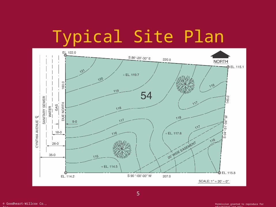
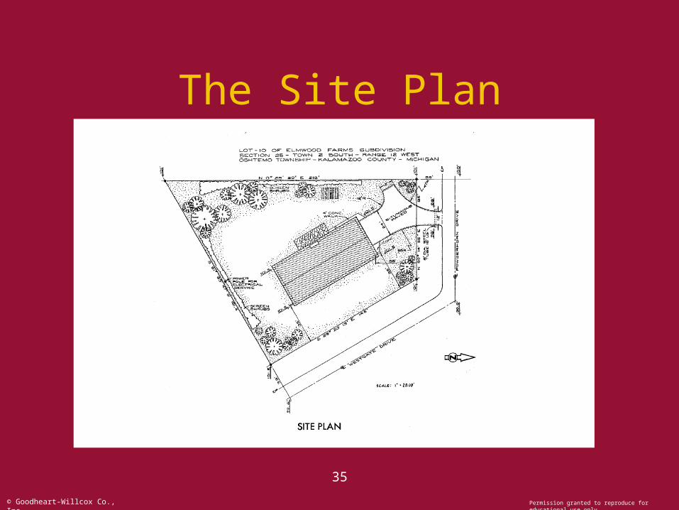
• The purpose of a site plan is to show the property lines and the existing topography of the site.– Length and bearing of each property line– Contour of the land– Meridian arrow– Existing streets, driveways, sidewalks and patios.– Lot number or address of the site– Scale of the drawing
5
© Goodheart-Willcox Co., Inc. Permission granted to reproduce for educational use only
Typical Site Plan
6
© Goodheart-Willcox Co., Inc. Permission granted to reproduce for educational use only
Plot Plan Features
• Plot plans contain:– Length and bearing (direction) of each
property line.– Location, outline, and size of buildings on
the site.– Contour of the land.– Elevation of property corners and contour
lines.– Meridian arrow (north symbol).
7
© Goodheart-Willcox Co., Inc. Permission granted to reproduce for educational use only
Plot Plan Features• Plot plans also show:
– Trees, shrubs, streams, and gardens.– Streets, driveways, sidewalks, and patios.– Location of utilities.– Easements for utilities and drainage.– Well, septic tank, and leach field.– Fences and retaining walls.– Lot number or address of the site.– Scale of the drawing.
8
© Goodheart-Willcox Co., Inc. Permission granted to reproduce for educational use only
Property Lines
• Property lines define the site boundaries.
• Length and bearing of each line are identified.
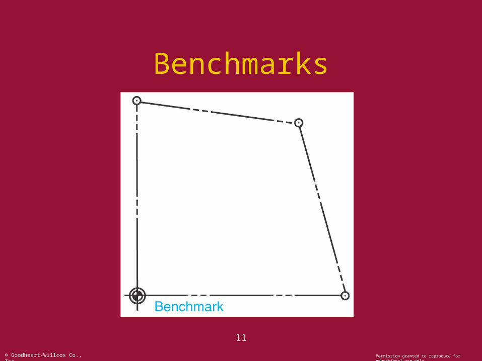
• Measured to 1/100 foot.• A benchmark is shown with a symbol
and represents a point of reference.• The order of drawing property lines is
clockwise.
9
© Goodheart-Willcox Co., Inc. Permission granted to reproduce for educational use only
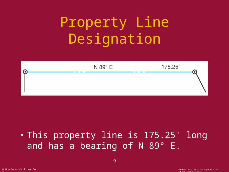
Property Line Designation
• This property line is 175.25' long and has a bearing of N 89° E.
10
© Goodheart-Willcox Co., Inc. Permission granted to reproduce for educational use only
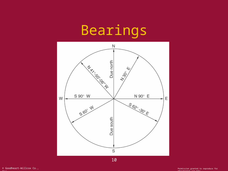
Bearings
11
© Goodheart-Willcox Co., Inc. Permission granted to reproduce for educational use only
Benchmarks
12
© Goodheart-Willcox Co., Inc. Permission granted to reproduce for educational use only
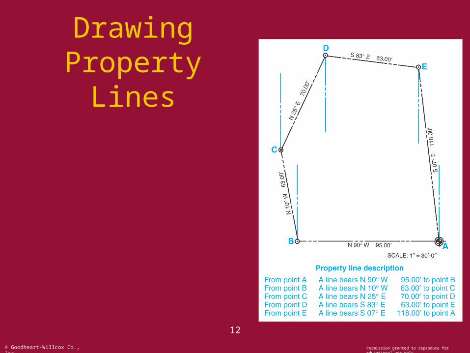
Drawing Property Lines
13
© Goodheart-Willcox Co., Inc. Permission granted to reproduce for educational use only
Contour Lines
• Contour lines help describe the topography of a site by depicting the shape and elevation of the land.
• Contour lines connect points that have the same elevation.
• Contour interval is the vertical distance between two adjacent contour lines.
14
© Goodheart-Willcox Co., Inc. Permission granted to reproduce for educational use only
Contour Terms and Features
• Closely spaced contour lines indicate a steep slope.
• Contours that are smooth and parallel show that the ground surface is even.
• Closed contour lines represent summits and depressions.
• Contour lines of different elevations do not cross.
15
© Goodheart-Willcox Co., Inc. Permission granted to reproduce for educational use only
Contour Lines
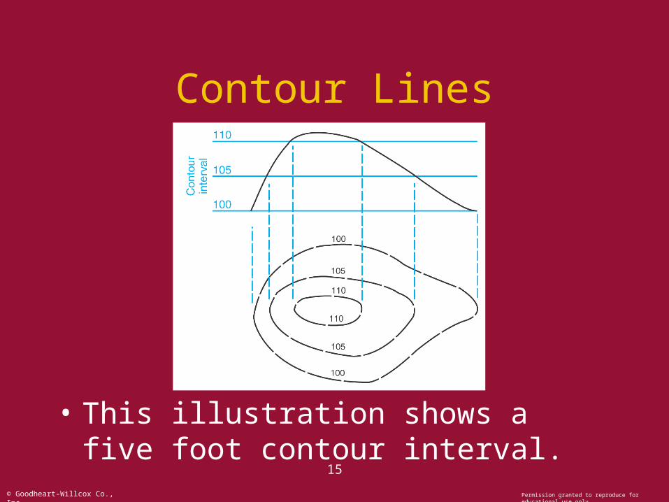
• This illustration shows a five foot contour interval.
16
© Goodheart-Willcox Co., Inc. Permission granted to reproduce for educational use only
Contour Lines
17
© Goodheart-Willcox Co., Inc. Permission granted to reproduce for educational use only
Contour Lines
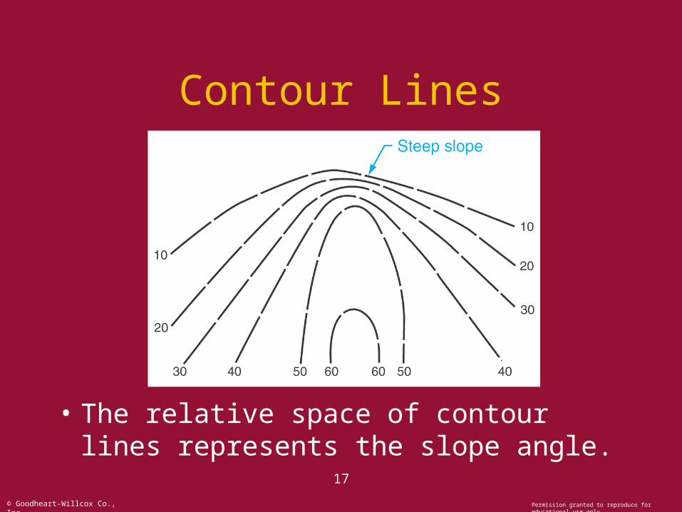
• The relative space of contour lines represents the slope angle.
18
© Goodheart-Willcox Co., Inc. Permission granted to reproduce for educational use only
Contour Lines
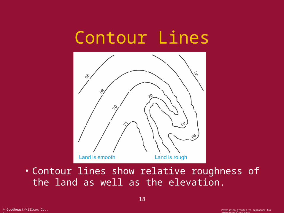
• Contour lines show relative roughness of the land as well as the elevation.
19
© Goodheart-Willcox Co., Inc. Permission granted to reproduce for educational use only
Contour Lines
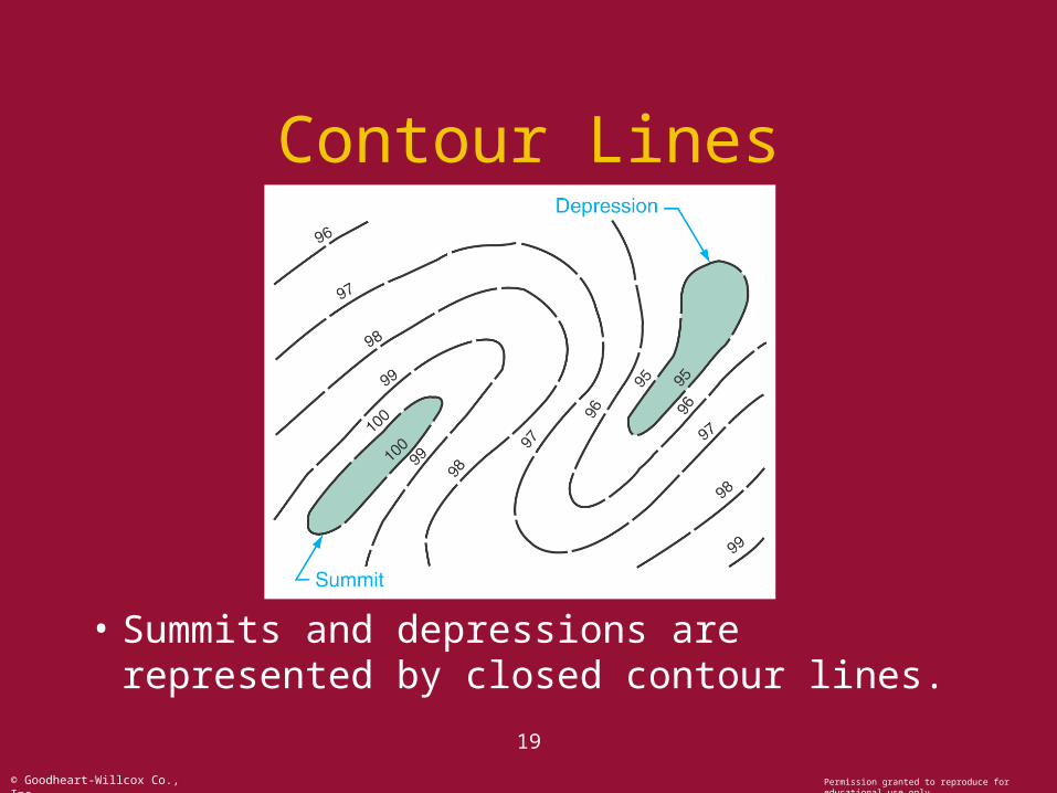
• Summits and depressions are represented by closed contour lines.
20
© Goodheart-Willcox Co., Inc. Permission granted to reproduce for educational use only
Contour Lines
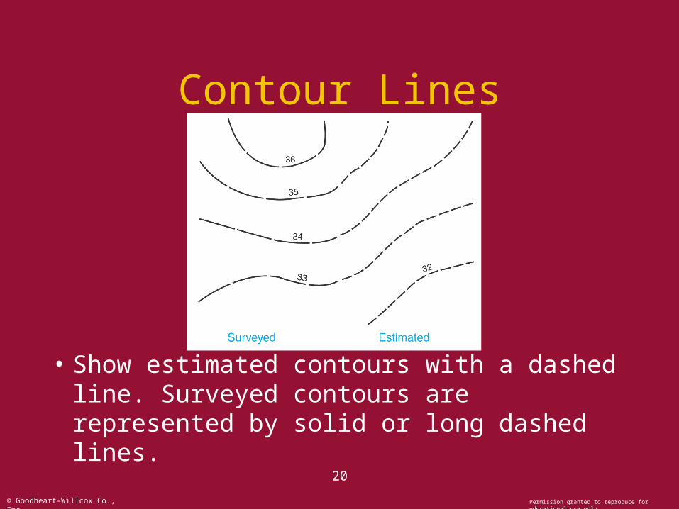
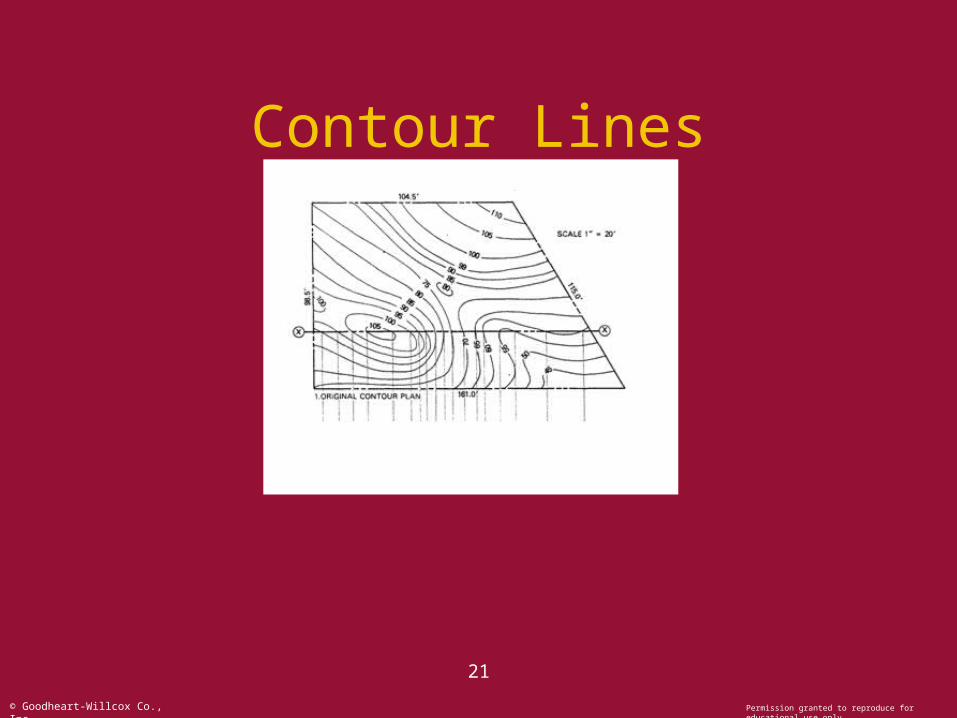
• Show estimated contours with a dashed line. Surveyed contours are represented by solid or long dashed lines.
21
© Goodheart-Willcox Co., Inc. Permission granted to reproduce for educational use only
Contour Lines
22
© Goodheart-Willcox Co., Inc. Permission granted to reproduce for educational use only
Contour Lines
23
© Goodheart-Willcox Co., Inc. Permission granted to reproduce for educational use only
Contour Lines
24
© Goodheart-Willcox Co., Inc. Permission granted to reproduce for educational use only
Contour Lines
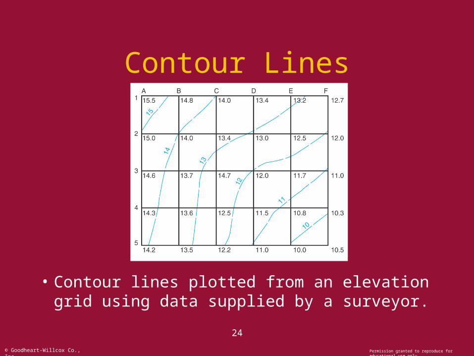
• Contour lines plotted from an elevation grid using data supplied by a surveyor.
25
© Goodheart-Willcox Co., Inc. Permission granted to reproduce for educational use only
Topographical Features
• Topographical features include:– Trees, shrubs, streams, roads, utilities,
fences, and similar features.
• These features are represented by symbols; most are standardized.
• Nonstandard symbols should appear with an explanation in a legend on the drawing.
26
© Goodheart-Willcox Co., Inc. Permission granted to reproduce for educational use only
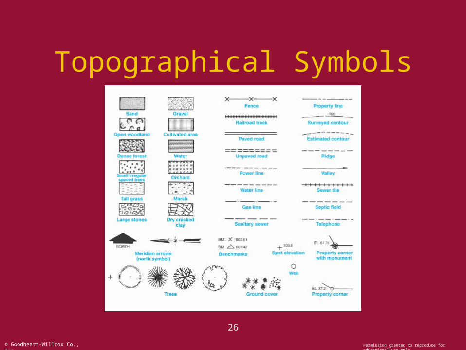
Topographical Symbols
27
© Goodheart-Willcox Co., Inc. Permission granted to reproduce for educational use only
Topographical Symbols
• When color is used with topographical symbols, follow these guidelines.– Black is used for lettering and human-built
works, such as roads, houses, etc.– Brown represents all land forms such as
contour lines.– Blue is used for water features.– Green is for vegetation.
28
© Goodheart-Willcox Co., Inc. Permission granted to reproduce for educational use only
Locating the Structure on Site
• Analyze the site to determine the ideal location for the structure.
• Analysis should include:– Natural contour, trees, view.– Surrounding houses, code restrictions.– Style of house to be built.– Solar orientation, winds.– Placement of well and septic system.– Size and shape of the site.
29
© Goodheart-Willcox Co., Inc. Permission granted to reproduce for educational use only
Locating the Structure on Site
• Once the location is decided on, the structure can be drawn on the plot plan.
• There are three commonly accepted methods of representing a house on the plot plan:– Lay out exterior walls and shade area.– Draw a typical roof plan.– Draw exterior walls thickened.
• Dimension the location of the structure on site.
30
© Goodheart-Willcox Co., Inc. Permission granted to reproduce for educational use only
Locating the Structure on Site
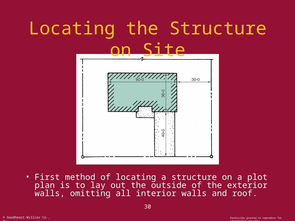
• First method of locating a structure on a plot plan is to lay out the outside of the exterior walls, omitting all interior walls and roof.
31
© Goodheart-Willcox Co., Inc. Permission granted to reproduce for educational use only
Locating the Structure on Site
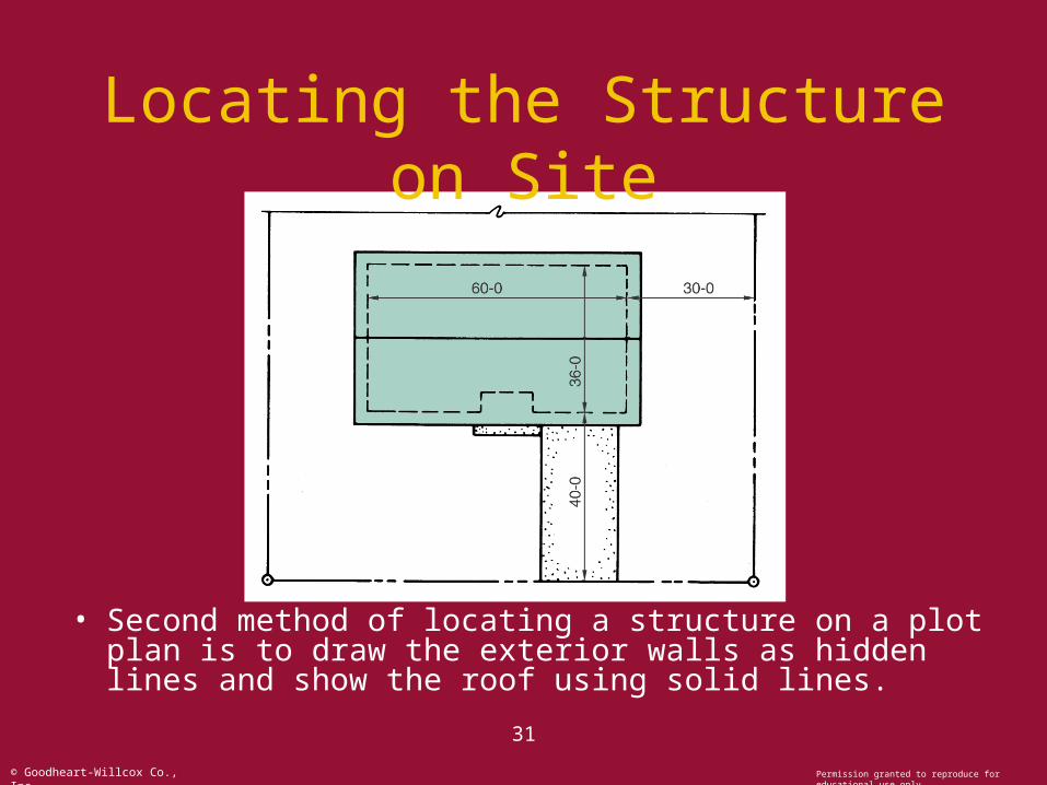
• Second method of locating a structure on a plot plan is to draw the exterior walls as hidden lines and show the roof using solid lines.
32
© Goodheart-Willcox Co., Inc. Permission granted to reproduce for educational use only
Locating the Structure on Site
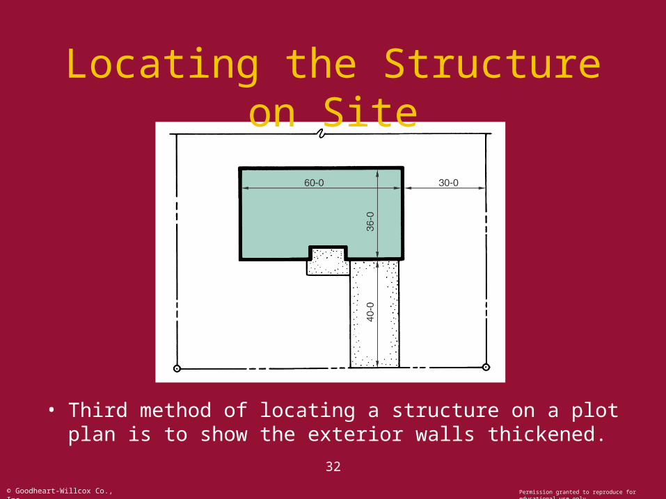
• Third method of locating a structure on a plot plan is to show the exterior walls thickened.
33
© Goodheart-Willcox Co., Inc. Permission granted to reproduce for educational use only
Locating the Structure on Site
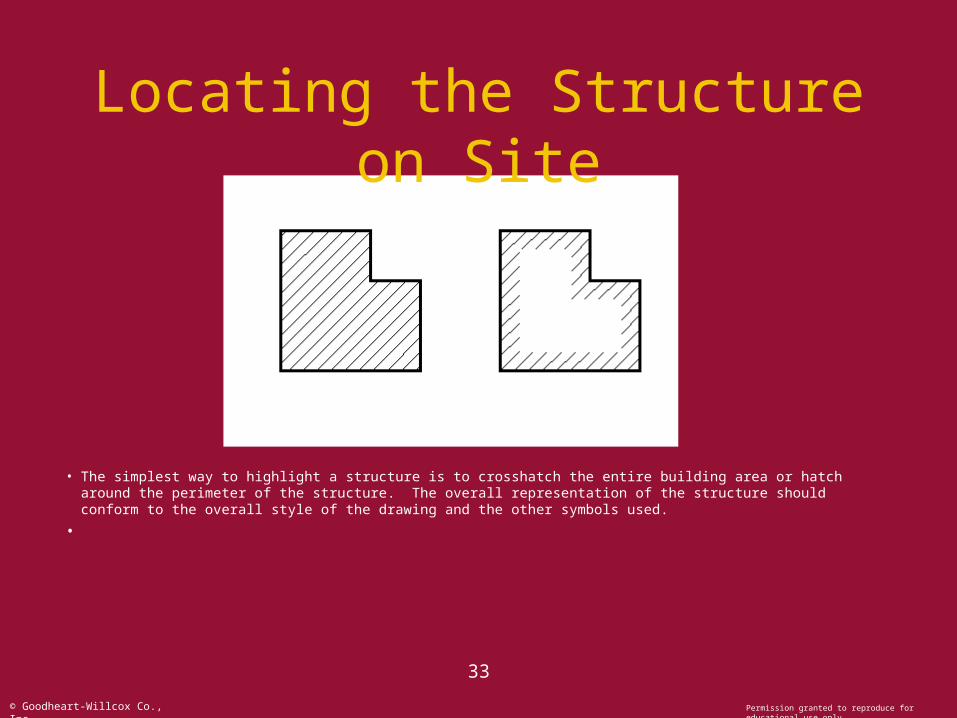
• The simplest way to highlight a structure is to crosshatch the entire building area or hatch around the perimeter of the structure. The overall representation of the structure should conform to the overall style of the drawing and the other symbols used.
•
34
© Goodheart-Willcox Co., Inc. Permission granted to reproduce for educational use only
Locating the Structure on Site
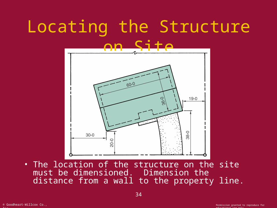
• The location of the structure on the site must be dimensioned. Dimension the distance from a wall to the property line.
35
© Goodheart-Willcox Co., Inc. Permission granted to reproduce for educational use only
The Site Plan