Embed Size (px)
Citation preview
CATALOGO 2011CATALOGUE 2011
www.futura-hnos.com

COMPROMISO COMMITMENT
CALIDAD & TECNOLOGIA QUALITY & TECNOLOGY
PROYECCION VISION
RESULTADOS RESULTS

IndiceContents
NOTA: Las medidas y datos de este catálogo están sujetos a revisión sin previo aviso, son solo a título informativo.NOTE: This catalogue contains data and sizes that may change without prior notice and are provided only for information only 03
NUESTRA EMPRESA OUR COMPANY04
CATALOGO DE PRODUCTOS CATALOGUE
TAPAS DE CIERRE RAPIDO QUICK OPENING CLOSURES
BRIDAS FLANGES
ACCESORIOS DE DERIVACION BRANCH FITTINGS
FIGURAS 8 FIGURES 8 BLANKS
FORJA GENERAL PARA LA INDUSTRIA GENERAL FORGING FOR THE INDUSTRY
07
39
07
19
31
35
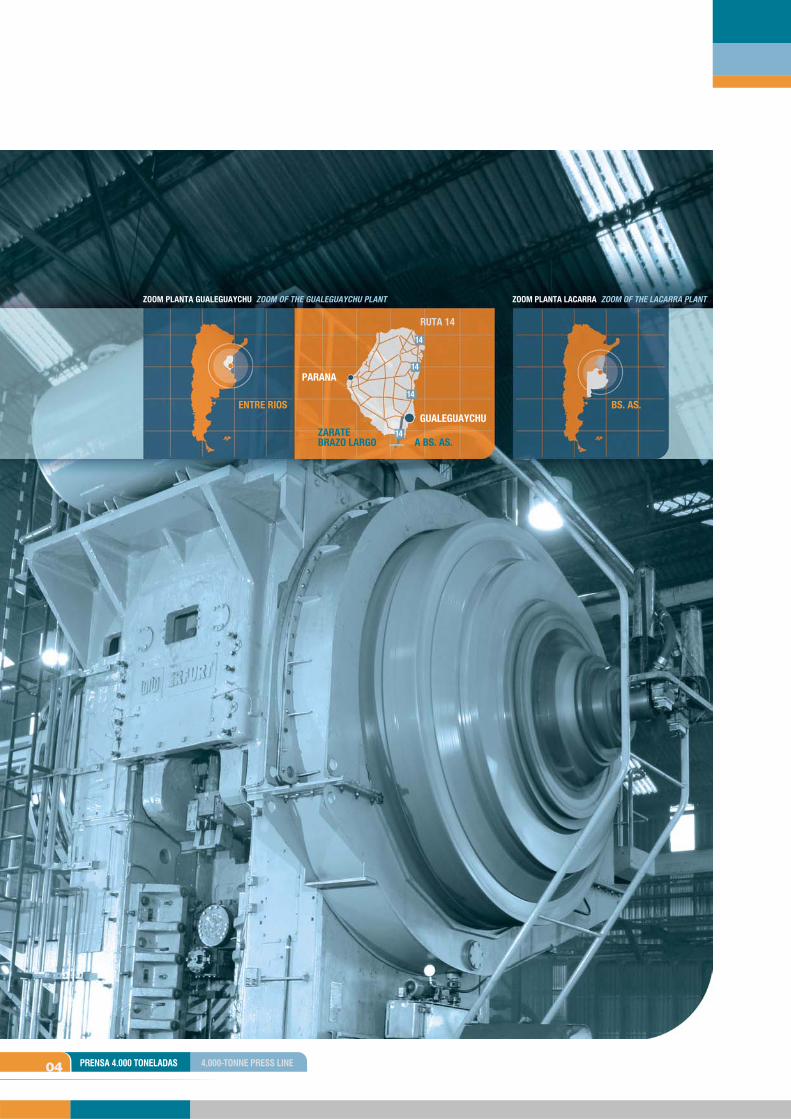
04 PRENSA 4.000 TONELADAS 4,000-TONNE PRESS LINE
ZOOM PLANTA GUALEGUAYCHU ZOOM OF THE GUALEGUAYCHU PLANT
BS. AS.ENTRE RIOS
RUTA 14
ZARATE BRAZO LARGO A BS. AS.
GUALEGUAYCHU
PARANA
ZOOM PLANTA LACARRA ZOOM OF THE LACARRA PLANT
Nuestra EmpresaOur Company
05
Planta de forja Gualeguaychú
La planta cuenta con los siguientes recursos:
Capacidad de producción de 1.000 toneladas por mes, 7.500 m2 y un equipamiento ideal para lograr costos competitivos.3 Líneas principales y completas de Forja compuestas por los Martillos UTA 25.000 y 16.000 Kgm., la prensa de 4.000 toneladas y por último la prensa de 1.300 toneladas. Estas tres líneas nos permiten abarcar todas las gamas de pesos y dimensiones con la maquinaria más adecuada. El área de matricería posee el diseño y la maquinaria para satisfacer el 100% de los desarrollos de la planta ya sean sencillos o de mayor complejidad como cigüeñales o puntas de ejes. Hornos de calentamiento de inducción y gas.Hornos de tratamiento térmico solamente para bridas.Laboratorio.Un staff comprometido y capacitado con un nivel de calificación exclusivo y propio de esta industria.
Planta Lacarra
Posee un rápido acceso a microcentro y a la zona de transporte de La Plata. Fue diseñada para establecer el centro logístico estratégico de Futura.
La planta cuenta con 3.000 m2 y permite distribuir de forma eficiente y coordinada el área de ventas, expedición, depósito y producción.
El área de producción, por una decisión estratégica, se divide en dos sectores: Bridas y Tapas de Cierre Rápido.
La logística de Futura permite distribuir los productos a todo el interior del país como así también al exterior.
Gualeguaychu forging plant
Features:
Production capacity of 1,000 tonnes per month in a surface of 7,500 m2 and top-line equipment to ensure competitive costs.The 3 complete forging lines include the UTA hammer line of 25,000 kg and 16,000 kg UTA hammer line, 4,000 and 1,300-ton press line. This ensures that the whole range of weights and sizes is covered with the most appropriate equipment.The die stamping section provides design and machinery to satisfy 100% of simple and high complexity plant developments such as crankshafts or CV joints.Induction and gas furnaces.Heat treatment furnaces exclusively for flanges.Laboratory.Committed and highly trained staff, with industry-specific skills and qualifications.
Lacarra Plant
The plant was designed to house Futura’s strategic logistics center, with easy access to the downtown and transportation areas.
The plant’s surface area of 3,000 m2 allows an efficient and coordinated layout of the sales, shipping, storage and production sections.
A strategic decision led to reorganization of the production section into two subsections: Flanges and Quick-Opening Closures.
Futura’s logistics organization enables nationwide and international product distribution.
06
Futura Hnos S.R.L.
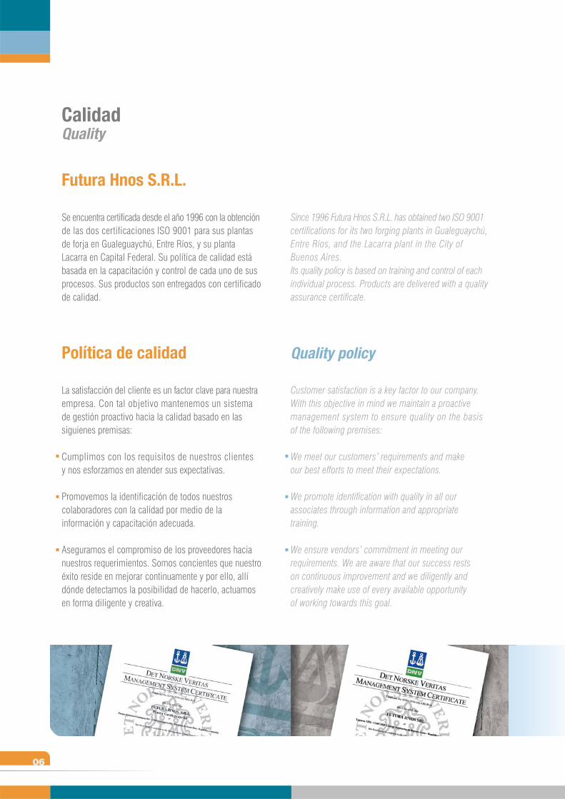
Se encuentra certificada desde el año 1996 con la obtención de las dos certificaciones ISO 9001 para sus plantas de forja en Gualeguaychú, Entre Ríos, y su planta Lacarra en Capital Federal. Su política de calidad está basada en la capacitación y control de cada uno de sus procesos. Sus productos son entregados con certificado de calidad.
Política de calidad
La satisfacción del cliente es un factor clave para nuestra empresa. Con tal objetivo mantenemos un sistema de gestión proactivo hacia la calidad basado en las siguienes premisas:
Cumplimos con los requisitos de nuestros clientes y nos esforzamos en atender sus expectativas.
Promovemos la identificación de todos nuestros colaboradores con la calidad por medio de la información y capacitación adecuada.
Aseguramos el compromiso de los proveedores hacia nuestros requerimientos. Somos concientes que nuestro éxito reside en mejorar continuamente y por ello, allí dónde detectamos la posibilidad de hacerlo, actuamos en forma diligente y creativa.
Since 1996 Futura Hnos S.R.L. has obtained two ISO 9001 certifications for its two forging plants in Gualeguaychú, Entre Ríos, and the Lacarra plant in the City of Buenos Aires.Its quality policy is based on training and control of each individual process. Products are delivered with a quality assurance certificate.
Quality policy
Customer satisfaction is a key factor to our company. With this objective in mind we maintain a proactive management system to ensure quality on the basis of the following premises:
We meet our customers’ requirements and make our best efforts to meet their expectations.
We promote identification with quality in all our associates through information and appropriate training.
We ensure vendors’ commitment in meeting our requirements. We are aware that our success rests on continuous improvement and we diligently and creatively make use of every available opportunity of working towards this goal.
CalidadQuality

Tapas de Cierre RápidoQuick Opening Closures
T
La innovación permanenteConstant Innovation
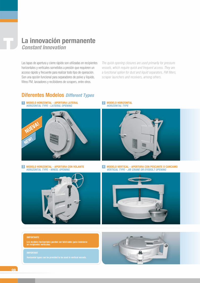
Diferentes Modelos Different Types
T
08
Las tapas de apertura y cierre rápido son utilizadas en recipientes horizontales y verticales sometidos a presión que requieren un acceso rápido y frecuente para realizar todo tipo de operación. Son una opción funcional para separadores de polvo y líquido, filtros FM, lanzadores y recibidores de scrapers, entre otros.
MODELO HORIZONTAL - APERTURA LATERALHORIZONTAL TYPE - LATERAL OPENING
MODELO VERTICAL - APERTURA CON PESCANTE O CANCAMOVERTICAL TYPE - JIB CRANE OR EYEBOLT OPENING
MODELO HORIZONTAL - APERTURA CON VOLANTEHORIZONTAL TYPE - WHEEL OPENING
MODELO HORIZONTALHORIZONTAL TYPE
The quick opening closures are used primarily for pressure vessels, which require quick and frequent access. They are a functional option for dust and liquid separators, FM filters, scraper launchers and receivers, among others.
1 2
3 4
NUEVA!
NEW!
Los modelos horizontales pueden ser fabricados para instalarse en recipientes verticales.
IMPORTANTE
Horizontal types can be provided to be used in vertical vessels.
IMPORTANT
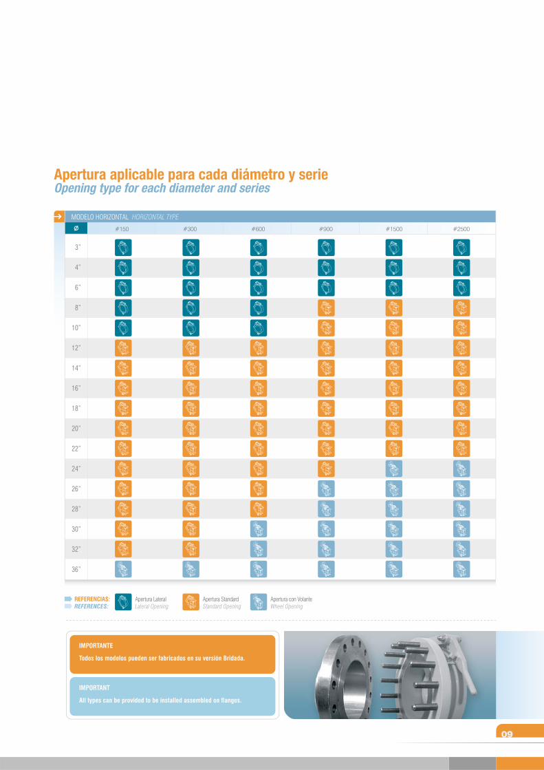
Apertura aplicable para cada diámetro y serieOpening type for each diameter and series
09
REFERENCIAS:REFERENCES:
Apertura LateralLateral Opening
Apertura StandardStandard Opening
Apertura con VolanteWheel Opening
MODELO HORIZONTAL HORIZONTAL TYPE
#2500#1500#600 #900#300#150
3”
4”
6”
8”
10”
12”
14”
16”
18”
20”
22”
24”
26”
28”
30”
32”
36”
Todos los modelos pueden ser fabricados en su versión Bridada.
IMPORTANTE
All types can be provided to be installed assembled on flanges.
IMPORTANT
T
10
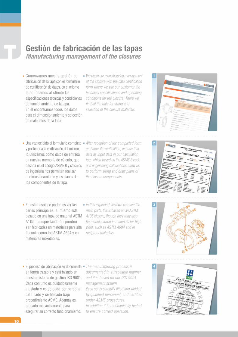
Comenzamos nuestra gestión de fabricación de la tapa con el formulario de certificación de datos, en el mismo le solicitamos al cliente lasespecificaciones técnicas y condiciones de funcionamiento de la tapa.En él encontramos todos los datos para el dimensionamiento y selección de materiales de la tapa.
Una vez recibido el formulario completo y posterior a la verificación del mismo, lo utilizamos como datos de entrada en nuestra memoria de cálculo, que basada en el código ASME 8 y cálculos de ingeniería nos permiten realizar el dimesionamiento y los planos de los componentes de la tapa.
En este despiece podemos ver las partes principales, el mismo está basado en una tapa de material ASTM A105, aunque también pueden ser fabricadas en materiales para alta fluencia como los ASTM A694 y en materiales inoxidables.
El proceso de fabricación se documenta en forma trazable y está basado en nuestro sistema de gestión ISO 9001. Cada conjunto es cuidadosamente ajustado y es soldado por personal calificado y certificado bajo procedimiento ASME. Además es probado mecánicamente para asegurar su correcto funcionamiento.
We begin our manufacturing management of the closure with the data certification form where we ask our customer the technical specifications and operating conditions for the closure. There we find all the data for sizing and selection of the closure materials.
After reception of the completed form and after its verification, we use that data as input data in our calculation log, which based on the ASME 8 code and engineering calculations allow us to perform sizing and draw plans of the closure components.
In this exploded view we can see the main parts; this is based on an ASTM A105 closure, though they may also be manufactured in materials for high yield, such as ASTM A694 and in rustproof materials.
The manufacturing process is documented in a traceable manner and it is based on our ISO 9001 management system. Each set is carefully fitted and welded by qualified personnel, and certified under ASME procedures. In addition it is mechanically tested to ensure correct operation.
Gestión de fabricación de las tapas Manufacturing management of the closures
1
2
3
4
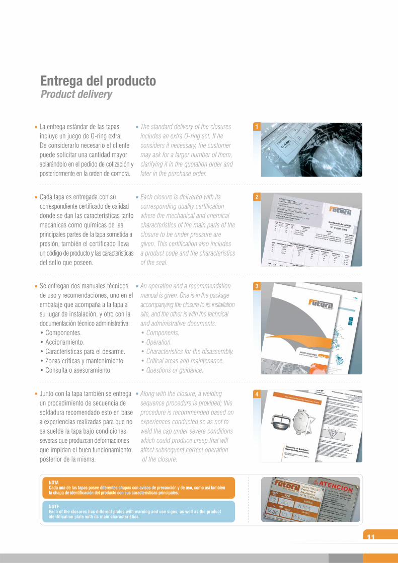
La entrega estándar de las tapas incluye un juego de O-ring extra. De considerarlo necesario el cliente puede solicitar una cantidad mayor aclarándolo en el pedido de cotización y posteriormente en la orden de compra.
Cada tapa es entregada con su correspondiente certificado de calidad donde se dan las características tanto mecánicas como químicas de las principales partes de la tapa sometida a presión, también el certificado lleva un código de producto y las características del sello que poseen.
Se entregan dos manuales técnicos de uso y recomendaciones, uno en el embalaje que acompaña a la tapa a su lugar de instalación, y otro con la documentación técnico administrativa:• Componentes. • Accionamiento. • Características para el desarme. • Zonas críticas y mantenimiento. • Consulta o asesoramiento.
Junto con la tapa también se entrega un procedimiento de secuencia de soldadura recomendado esto en base a experiencias realizadas para que no se suelde la tapa bajo condiciones severas que produzcan deformaciones que impidan el buen funcionamiento posterior de la misma.
The standard delivery of the closures includes an extra O-ring set. If he considers it necessary, the customer may ask for a larger number of them, clarifying it in the quotation order and later in the purchase order.
Each closure is delivered with its corresponding quality certification where the mechanical and chemical characteristics of the main parts of the closure to be under pressure are given. This certification also includes a product code and the characteristics of the seal.
An operation and a recommendation manual is given. One is in the package accompanying the closure to its installation site, and the other is with the technical and administrative documents:• Components.• Operation.• Characteristics for the disassembly.• Critical areas and maintenance.• Questions or guidance.
Along with the closure, a welding sequence procedure is provided; this procedure is recommended based on experiences conducted so as not to weld the cap under severe conditions which could produce creep that will affect subsequent correct operation of the closure.
1
2
3
4
11
Entrega del productoProduct delivery
NOTACada una de las tapas posee diferentes chapas con avisos de precaución y de uso, como así también la chapa de identificación del producto con sus características principales.
NOTEEach of the closures has different plates with warning and use signs, as well as the product identification plate with its main characteristics.
T
12
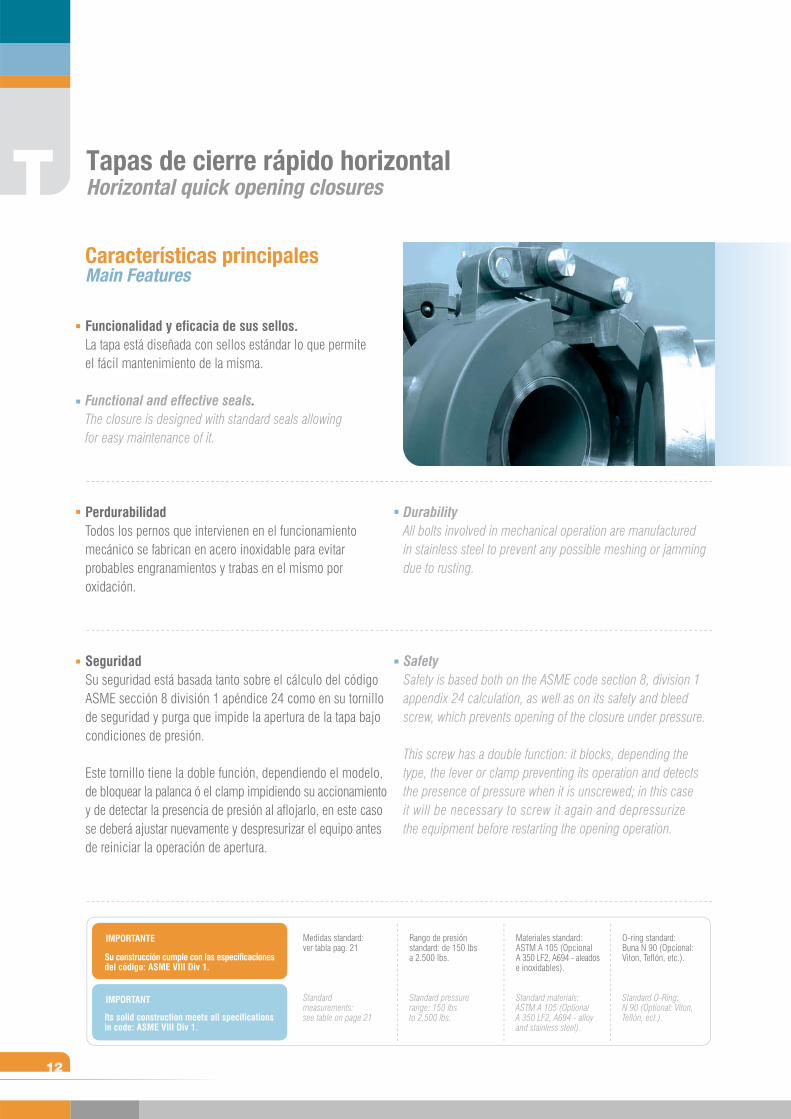
Funcionalidad y eficacia de sus sellos.La tapa está diseñada con sellos estándar lo que permite el fácil mantenimiento de la misma.
Functional and effective seals.The closure is designed with standard seals allowing for easy maintenance of it.
Perdurabilidad Todos los pernos que intervienen en el funcionamiento mecánico se fabrican en acero inoxidable para evitar probables engranamientos y trabas en el mismo por oxidación.
SeguridadSu seguridad está basada tanto sobre el cálculo del código ASME sección 8 división 1 apéndice 24 como en su tornillo de seguridad y purga que impide la apertura de la tapa bajo condiciones de presión.
Este tornillo tiene la doble función, dependiendo el modelo, de bloquear la palanca ó el clamp impidiendo su accionamiento y de detectar la presencia de presión al aflojarlo, en este caso se deberá ajustar nuevamente y despresurizar el equipo antes de reiniciar la operación de apertura.
Características principalesMain Features
DurabilityAll bolts involved in mechanical operation are manufactured in stainless steel to prevent any possible meshing or jamming due to rusting.
SafetySafety is based both on the ASME code section 8, division 1 appendix 24 calculation, as well as on its safety and bleed screw, which prevents opening of the closure under pressure.
This screw has a double function: it blocks, depending the type, the lever or clamp preventing its operation and detects the presence of pressure when it is unscrewed; in this case it will be necessary to screw it again and depressurize the equipment before restarting the opening operation.
IMPORTANTE
IMPORTANT
Tapas de cierre rápido horizontalHorizontal quick opening closures
Su construcción cumple con las especificaciones del código: ASME VIII Div 1.
Its solid construction meets all specifications in code: ASME VIII Div 1.
Medidas standard: ver tabla pag. 21
Standard measurements: see table on page 21
Rango de presión standard: de 150 lbs a 2.500 lbs.
Standard pressure range: 150 lbs to 2,500 lbs.
Materiales standard: ASTM A 105 (Opcional A 350 LF2, A694 - aleados e inoxidables).
Standard materials: ASTM A 105 (Optional A 350 LF2, A694 - alloy and stainless steel).
O-ring standard: Buna N 90 (Opcional: Viton, Teflón, etc.).
Standard O-Ring: N 90 (Optional: Viton, Teflón, ect.).
13
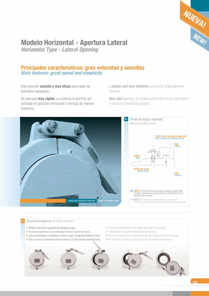
Una solución sencilla y muy eficaz para tapas de diámetros pequeños.
De apertura muy rápida, su sistema le permite ser utilizada en posición horizontal o vertical de manera indistinta.
A simple and very effective solution for small diameter closures.
Very fast opening, the system allows them to be used either in vertical or horizontal position.
Modelo Horizontal - Apertura LateralHorizontal Type - Lateral Opening
Principales características: gran velocidad y sencillezMain features: great speed and simplicity
Secuencia de apertura Actuation sequence
Aflojar el tornillo de seguridad que bloquea el yugo. Accionar la palanca lo suficiente para liberar el perno de cierre.Una vez destrabado el mecanismo volcar el yugo y la tapa para liberar el cierre.Para el cierre se procede de forma inversa a lo mencionado anteriormente.
First loosen the safety screw which will unblock the clamp.Pull the lever enough to release the locking bolt.Once the mechanism is unlocked dump the clamp and closure to open.To close the closure you should proceed in reverse to the above.
NOTA: El tornillo de purga bloquea la palanca cuando está cerrada, impidiendo su accionamiento si previamente no se despresuriza el equipo.
NOTE: The bleed screw blocks the lever when closed, preventing actuation unless equipment has been depressurized.
Tornillo de purga y seguridadBleed and safety screw
TapaClosure
YugoClamp
Tornillo inox. de purga y seguridadWell safety and drainage screw
Orificio de purgaDrain orifice
CuerpoBody
NUEVA!NEW!
DETAIL OF OPENING SYSTEMDETALLE DEL SISTEMA DE APERTURA
T
14
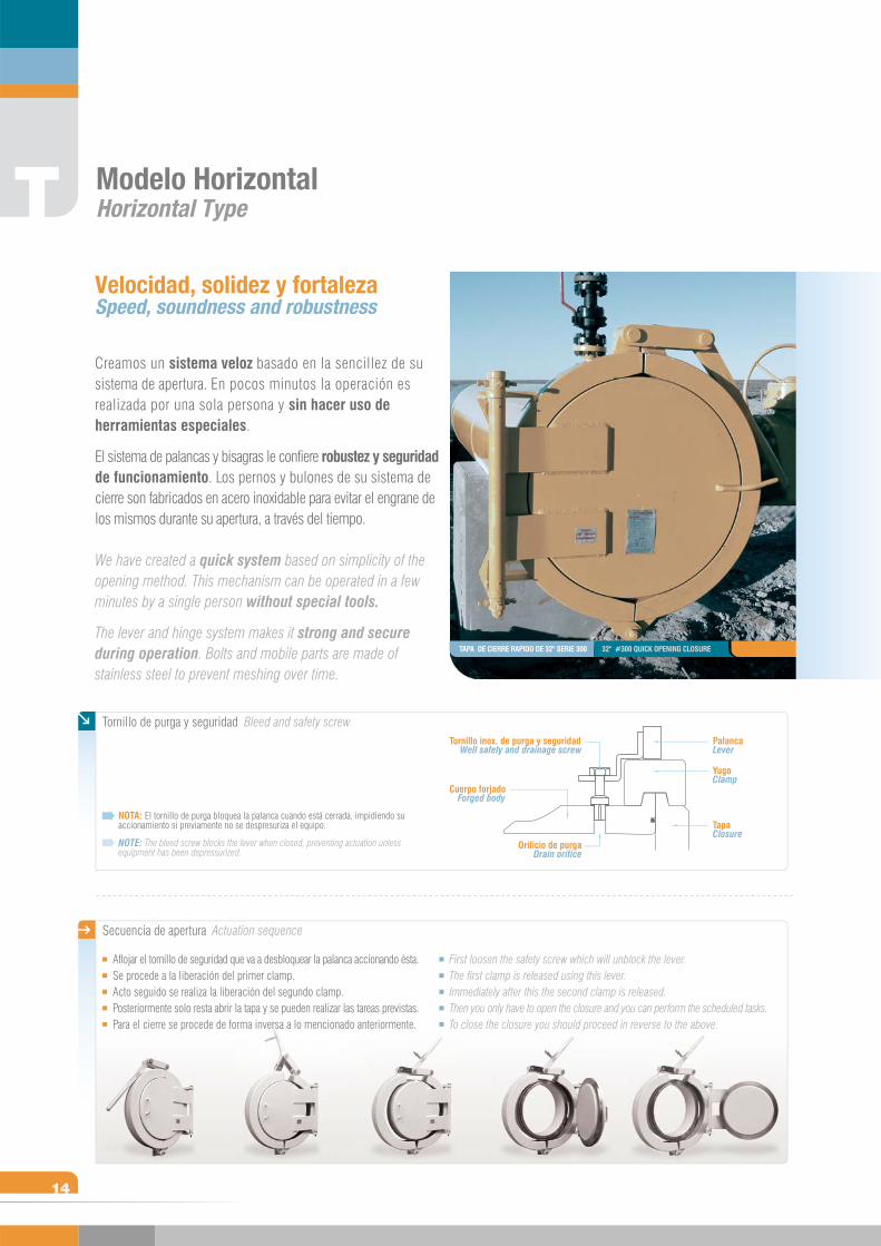
Creamos un sistema veloz basado en la sencillez de su sistema de apertura. En pocos minutos la operación es realizada por una sola persona y sin hacer uso de herramientas especiales.
El sistema de palancas y bisagras le confiere robustez y seguridad de funcionamiento. Los pernos y bulones de su sistema de cierre son fabricados en acero inoxidable para evitar el engrane de los mismos durante su apertura, a través del tiempo.
We have created a quick system based on simplicity of the opening method. This mechanism can be operated in a few minutes by a single person without special tools.
The lever and hinge system makes it strong and secure
during operation. Bolts and mobile parts are made of stainless steel to prevent meshing over time.
Modelo HorizontalHorizontal Type
Velocidad, solidez y fortaleza Speed, soundness and robustness
TapaClosure
Orificio de purgaDrain orifice
Cuerpo forjadoForged body
YugoClamp
Tornillo inox. de purga y seguridadWell safety and drainage screw
PalancaLever
NOTA: El tornillo de purga bloquea la palanca cuando está cerrada, impidiendo su accionamiento si previamente no se despresuriza el equipo.
NOTE: The bleed screw blocks the lever when closed, preventing actuation unless equipment has been depressurized.
Secuencia de apertura Actuation sequence
Tornillo de purga y seguridad Bleed and safety screw
Aflojar el tornillo de seguridad que va a desbloquear la palanca accionando ésta. Se procede a la liberación del primer clamp.Acto seguido se realiza la liberación del segundo clamp.Posteriormente solo resta abrir la tapa y se pueden realizar las tareas previstas.Para el cierre se procede de forma inversa a lo mencionado anteriormente.
First loosen the safety screw which will unblock the lever.The first clamp is released using this lever.Immediately after this the second clamp is released.Then you only have to open the closure and you can perform the scheduled tasks. To close the closure you should proceed in reverse to the above.
TAPA DE CIERRE RAPIDO DE 32" SERIE 300 32" #300 QUICK OPENING CLOSURE
15
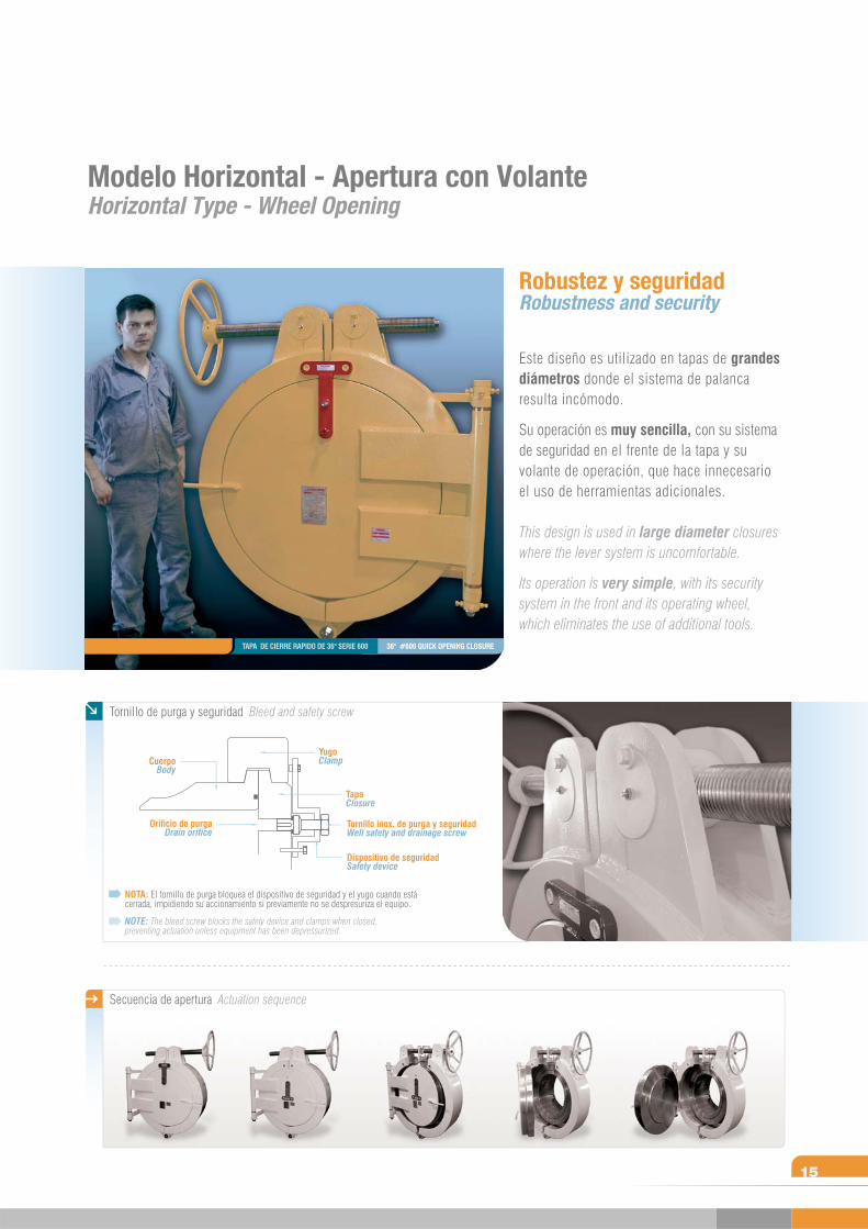
Este diseño es utilizado en tapas de grandes diámetros donde el sistema de palanca resulta incómodo.
Su operación es muy sencilla, con su sistema de seguridad en el frente de la tapa y su volante de operación, que hace innecesario el uso de herramientas adicionales.
This design is used in large diameter closures where the lever system is uncomfortable.
Its operation is very simple, with its security system in the front and its operating wheel, which eliminates the use of additional tools.
Modelo Horizontal - Apertura con VolanteHorizontal Type - Wheel Opening
Robustez y seguridadRobustness and security
36" #600 QUICK OPENING CLOSURETAPA DE CIERRE RAPIDO DE 36" SERIE 600
Tornillo de purga y seguridad Bleed and safety screw
NOTA: El tornillo de purga bloquea el dispositivo de seguridad y el yugo cuando está cerrada, impidiendo su accionamiento si previamente no se despresuriza el equipo.
NOTE: The bleed screw blocks the safety device and clamps when closed, preventing actuation unless equipment has been depressurized.
TapaClosure
YugoClamp
Tornillo inox. de purga y seguridadWell safety and drainage screw
Dispositivo de seguridadSafety device
Orificio de purgaDrain orifice
CuerpoBody
Secuencia de apertura Actuation sequence
T
16
Modelo VerticalVertical Type
Principales ventajas competitivas: robustez, seguridad y economía Main competitive advantages: robustness, safety and economy
Secuencia de apertura con volante Wheel actuation sequence
Tornillo de purga y seguridad Bleed and safety screw
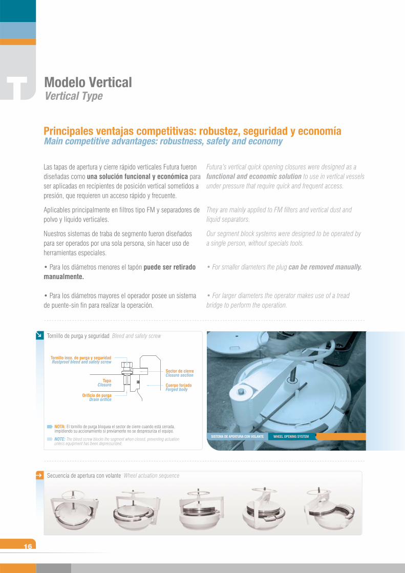
NOTA: El tornillo de purga bloquea el sector de cierre cuando está cerrada, impidiendo su accionamiento si previamente no se despresuriza el equipo.
NOTE: The bleed screw blocks the segment when closed, preventing actuation unless equipment has been depressurized.
TapaClosure Cuerpo forjado
Forged body
Orificio de purgaDrain orifice
Tornillo inox. de purga y seguridadRustproof bleed and safety screw
Sector de cierreClosure section
Las tapas de apertura y cierre rápido verticales Futura fueron diseñadas como una solución funcional y económica para ser aplicadas en recipientes de posición vertical sometidos a presión, que requieren un acceso rápido y frecuente.
Aplicables principalmente en filtros tipo FM y separadores de polvo y líquido verticales.
Nuestros sistemas de traba de segmento fueron diseñados para ser operados por una sola persona, sin hacer uso de herramientas especiales.
• Para los diámetros menores el tapón puede ser retirado manualmente.
• Para los diámetros mayores el operador posee un sistema de puente-sin fin para realizar la operación.
Futura’s vertical quick opening closures were designed as a functional and economic solution to use in vertical vessels under pressure that require quick and frequent access.
They are mainly applied to FM filters and vertical dust and liquid separators.
Our segment block systems were designed to be operated by a single person, without specials tools.
• For smaller diameters the plug can be removed manually.
• For larger diameters the operator makes use of a tread bridge to perform the operation.
SISTEMA DE APERTURA CON VOLANTE WHEEL OPENING SYSTEM
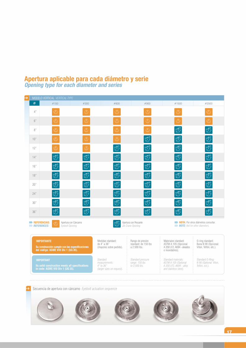
NOTA: Por otros diámetros consultar.NOTE: Ask for other diameters.
Secuencia de apertura con cáncamo Eyebolt actuation sequence
Apertura aplicable para cada diámetro y serieOpening type for each diameter and series
17
REFERENCIAS:REFERENCES:
Apertura con CáncamoEyebolt Opening
Apertura con PescanteJib Crane Opening
MODELO VERTICAL VERTICAL TYPE
#2500#1500#600 #900#300#150
4”
6”
8”
10”
12”
14”
16”
18”
20”
24”
30”
36”
IMPORTANTE
IMPORTANT
Su construcción cumple con las especificaciones del código: ASME VIII Div 1 (UG 35).
Its solid construction meets all specifications in code: ASME VIII Div 1 (UG 35).
Medidas standard: de 4” a 36” (mayores sobre pedido).
Standard measurements: 4“ to 36”(larger sizes on request).
Rango de presión standard: de 150 lbs a 2.500 lbs.
Standard pressure range: 150 lbs to 2,500 lbs.
Materiales standard: ASTM A 105 (Opcional A 350 LF2, A694 - aleados e inoxidables).
Standard materials: ASTM A 105 (Optional A 350 LF2, A694 - alloy and stainless steel).
O-ring standard: Buna N 90 (Opcional: Viton, Teflón, etc.).
Standard O-Ring: N 90 (Optional: Viton, Teflón, ect.).
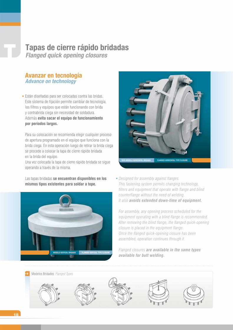
Modelos Bridados Flanged Types
T
18
Están diseñadas para ser colocadas contra las bridas. Este sistema de fijación permite cambiar de tecnología, los filtros y equipos que están funcionando con brida y contrabrida ciega sin necesidad de soldadura. Además evita sacar el equipo de funcionamiento por períodos largos.
Para su colocación se recomienda elegir cualquier proceso de apertura programado en el equipo que funciona con la brida ciega. En esta operación luego de retirar la brida ciega se procede a colocar la tapa de cierre rápido bridada en la brida del equipo.Una vez colocada la tapa de cierre rápido bridada se sigue operando a través de la misma.
Las tapas bridadas se encuentran disponibles en los mismos tipos existentes para soldar a tope.
Avanzar en tecnologíaAdvance on technology
Designed for assembly against flanges. This fastening system permits changing technology, filters and equipment that operate with flange and blind counterflange without the need of welding.It also avoids extended down-time of equipment.
For assembly, any opening process scheduled for the equipment operating with a blind flange is recommended. After removing the blind flange, the flanged quick-opening closure is placed in the equipment flange.Once the flanged quick-opening closure has been assembled, operation continues through it.
Flanged closures are available in the same types available for butt welding.
Tapas de cierre rápido bridadasFlanged quick opening closures
FLANGED VERTICAL TYPE CLOSUREMODELO VERTICAL BRIDADO
TAPA MODELO HORIZONTAL BRIDADA FLANGED HORIZONTAL TYPE CLOSURE
BridasFlanges
B
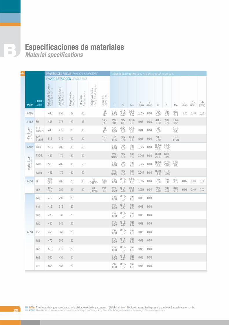
Especificaciones de materiales Material specifications
GRADEGRADO
Resis
tenc
ia Tra
cció
n (1)
Tens
ile S
treng
th (1
)
Lím
ite d
e El
ástic
o (1
)Yie
ld S
tress
(1)
Alar
gam
iento
%Elo
ngati
on%
Estri
cció
n%Ar
ea re
ducti
on%
Char
py Jo
ule
(min
.)Ch
arpy
test
Joule
s (m
in.)
Dure
za H
BHa
rdne
ss H
B
COMPOSICION QUIMICA % CHEMICAL COMPOSITION %
ENSAYO DE TRACCION TENSILE TEST
PROPIEDADES FISICAS PHYSICAL PROPERTIES
F5
F11Clase2
F22Clase3
F304
F304L
F316
F316L
LF1
LF2
F42
F46
F48
F50
F52
F56
F60
F65
F70
250
275
275
310
205
170
205
170
205
250
290
315
330
345
360
385
415
450
485
22
20
20
20
30
30
30
30
25
22
20
20
20
20
20
20
20
20
20
30
35
30
30
50
50
50
50
38
30
18 (-29ºC)
20 (-46ºC)
137-187
143-217
143-207
156-207
max.197
max.197
C
max.0,35
max.015
0,10-0,20
0,05-0,15
max.0,08
max.0,030
max.0,08
max.0,030
max.0,30
max.0,30
max.0,30
max.0,30
max.0,30
max.0,30
max.0,30
max.0,30
max.0,30
max.0,30
max.0,30
Si
0,10-0,35
max.050
0,50-1,00
max.0,50
max.1,00
max.1,00
max.1,00
max.1,00
0,15-0,30
0,15-0,30
0,13-0,37
0,13-0,37
0,13-0,37
0,13-0,37
0,13-0,37
0,13-0,37
0,13-0,37
0,13-0,37
0,13-0,37
Mn
0,60-1,05
0,30-0,60
0,30-0,80
0,30-0,60
max.2,00
max.2,00
max.2,00
max.2,00
0,60-1,35
0,60-1,35
max.1,50
max.1,50
max.1,50
max.1,50
max.1,50
max.1,50
max.1,50
max.1,50
max.1,50
0,035
0,03
0,04
0,04
0,045
0,045
0,045
0,045
0,035
0,035
0,03
0,03
0,03
0,03
0,03
0,03
0,03
0,03
0,03
P(max)
S(max)
V(max)
Cu(max)
Nb(max)
0,04
0,03
0,04
0,04
0,03
0,03
0,03
0,03
0,04
0,04
0,03
0,03
0,03
0,03
0,03
0,03
0,03
0,03
0,03
Cr
max.0,30
4,00-6,00
1,00-1,50
2,00-2,50
18,00-20,00
18,00-20,00
16,00-18,00
16,00-18,00
max.0,30
max.0,30
Ni
max.0,40
max.0,50
8,00-11,00
8,00-13,00
10,00-14,00
10,00-15,00
max.0,40
max.0,40
Mo
max.0,12
0,44-0,65
0,44-0,65
0,87-11,30
2,00-3,00
max.0,12
max.0,12
0,05
0,05
0,05
0,40
0,40
0,40
0,02
0,02
0,02
485
485
485
515
515
485
515
485
415-585 485-655
415
415
425
440
455
470
515
530
565
NOTA: Tipo de materiales para uso estandard en la fabricación de bridas y accesorios. I (1) MPol mínimo. I El valor del ensayo de charpy es el promedio de 3 especímenes ensayados.NOTE: Materials for standard use in the manufacture of flanges and fittings. I (1) Min. MPa. I Charpy test value is the average of three test specimens.
ASTM
A-105
A-182
A-182
A-350
A-694
- Fer
ritic
os -
- Fer
ritic
-- A
uste
nitic
os -
- Aus
tenit
ic -
20
B
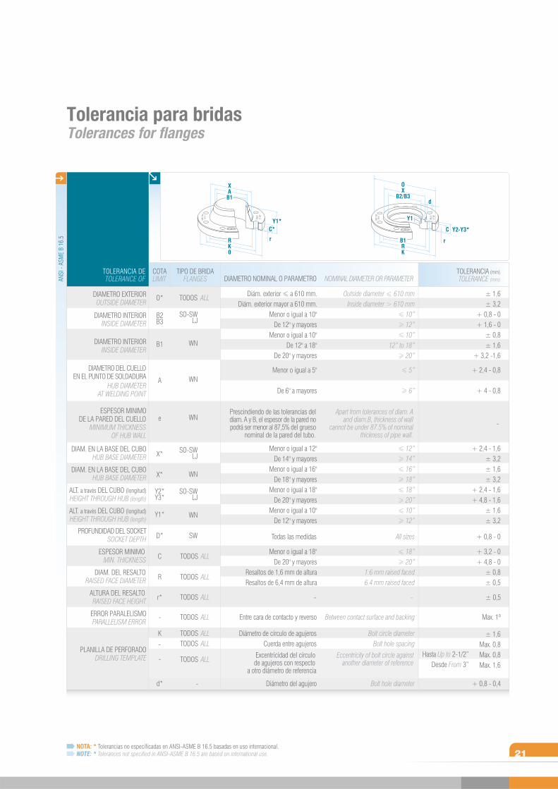
Tolerancia para bridas Tolerances for flanges
C*
rRK0
Y1*
OX
B2/B3
B1RK
r
Y3*C
d
-
Hasta Up to 2-1/2”Desde From 3”
± 1,6± 3,2
+ 0,8 - 0 + 1,6 - 0
± 0,8± 1,6
+ 3,2 -1,6 + 2,4 - 0,8
+ 4 - 0,8
TOLERANCE (mm).TOLERANCIA (mm).
+ 2,4 - 1,6± 3,2± 1,6± 3,2
+ 2,4 - 1,6+ 4,8 - 1,6
± 1,6± 3,2
+ 3,2 - 0+ 4,8 - 0
± 0,8± 0,5
± 1,6Max. 0,8Max. 0,8Max. 1,6
TOLERANCE OFTOLERANCIA DE
DIAMETRO EXTERIOR
DIAMETRO INTERIOR
DIAMETRO INTERIOR
ESPESOR MINIMODE LA PARED DEL CUELLO
DIAM. EN LA BASE DEL CUBO
DIAMETRO DEL CUELLOEN EL PUNTO DE SOLDADURA
DIAM. EN LA BASE DEL CUBO
ALT. a través DEL CUBO (longitud)
ESPESOR MINIMO
PLANILLA DE PERFORADO
DIAM. DEL RESALTO
ERROR PARALELISMO
ALTURA DEL RESALTO
ALT. a través DEL CUBO (longitud)
PROFUNDIDAD DEL SOCKET
OUTSIDE DIAMETER
INSIDE DIAMETER
INSIDE DIAMETER
MINIMUM THICKNESSOF HUB WALL
HUB BASE DIAMETER
HUB DIAMETERAT WELDING POINT
HUB BASE DIAMETER
HEIGHT THROUGH HUB (length)
MIN. THICKNESS
DRILLING TEMPLATE
RAISED FACE DIAMETER
PARALLELISM ERROR
RAISED FACE HEIGHT
HEIGHT THROUGH HUB (length)
SOCKET DEPTH
FLANGESTIPO DE BRIDA
DIAMETRO NOMINAL O PARAMETRO
-
LIMITCOTA
O*
B2B3
B1
A
e
X*
X*
Y2*Y3*
Y1*
D*
C
R
K
d*
r*
-
-
ALL
ALL
ALL
ALL
ALL
ALLALL
ALL
SO-SWLJ
WN
WN
WN
TODOS
TODOS
WN
WN
SW
SO-SWLJ
SO-SWLJ
TODOS
TODOS
TODOS
TODOSTODOS
TODOS
-
+ 0,8 - 0
+ 0,8 - 0,4
Max. 1º
ANSI
- AS
ME
B 16
.5
NOTA: * Tolerancias no especificadas en ANSI-ASME B 16.5 basadas en uso internacional. NOTE: * Tolerances not specified in ANSI-ASME B 16.5 are based on international use.
NOMINAL DIAMETER OR PARAMETER
-
Outside diameter 610 mmInside diameter 610 mm
10” 12” 10”
12” to 18” 20” 5”
6”
12” 14” 16” 18” 18” 20” 10” 12”
All sizes
Bolt circle diameterBolt hole spacing
Bolt hole diameter
18” 20”
1.6 mm raised faced6.4 mm raised faced
Between contact surface and backing
Eccentricity of bolt circle againstanother diameter of reference
Apart from tolerances of diam. A and diam.B, thickness of wall
cannot be under 87.5% of nominal thickness of pipe wall.
-
Diám. exterior a 610 mm.Diám. exterior mayor a 610 mm.
Menor o igual a 10"De 12" y mayores
Menor o igual a 10"De 12" a 18"
De 20" y mayores
Menor o igual a 5"
De 6" a mayores
Menor o igual a 12"De 14" y mayores
Menor o igual a 16"De 18" y mayores
Menor o igual a 18"De 20" y mayores
Menor o igual a 10"De 12" y mayores
Todas las medidas
Diámetro de círculo de agujerosCuerda entre agujeros
Excentricidad del círculo de agujeros con respecto
a otro diámetro de referencia
Diámetro del agujero
Menor o igual a 18"De 20" y mayores
Resaltos de 1,6 mm de alturaResaltos de 6,4 mm de altura
Entre cara de contacto y reverso
Prescindiendo de las tolerancias del diam. A y B, el espesor de la pared no podrá ser menor al 87,5% del grueso
nominal de la pared del tubo.
± 0,5
Y1
Y2-
XAB1
21
SERI
E / c
lass
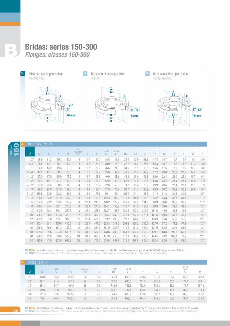
Bridas: series 150-300Flanges: classes 150-300
C B1sch 40
B1sch 80
ANSI B 16.5 1/2” - 24”
d A Y2 Y3Y1 T DR K B2 B3X rAGUJERO
HOLE
N
N
O
B
22
150
ASME B 16.47 “A”
NOTA: Las medidas son en milímetros. I Las tablas corresponden a bridas de cara c/ resalte. I La medida de espesor (c) y la altura total (Y1-Y2) incluye resalte de 1.6 mm.NOTE: Sizes stated in millimeters. I The tables correspond to raised face flanges. I Thickness (c) and total height (Y1 and Y2) include 1.6 mm raised face.
NOTA: Las medidas son en milímetros. I Las tablas corresponden a bridas de cara c/ resalte. I La medida de espesor (c) y la altura total (Y1) incluye resalte de 1.6 mm. I Por bridas SLIP-ON, consultar.NOTE: Sizes stated in millimeters. I The tables correspond to raised face flanges. I Thickness (c) and total height (Y1) include 1.6 mm raised face. I Please enquire about SLIP-ON flanges.
1/2”3/4”
1”1-1/4”1-1/2”
2”2-1/2”
3”3-1/2”
4”5”6”8”
10”12”14”16”18”20”24”
26”28”30”32”34”36”
O
870,0927,1984,3
1060,51111,31168,4
CWN
68,371,474,781,082,690,4
K
806,5863,6914,4977,9
1028,71085,4
AGUJEROHOLE
242828283232
d
35,135,135,141,141,141,1
B1sch STD
641,3692,2742,9793,7844,5895,3
B1sch XS
635,0685,8736,6787,4838,2889,0
A
660,4711,2762,0812,8863,6914,4
X
676,1726,9781,1831,9882,7933,5
Y1
120,7125,5136,2144,5149,4157,2
C
CIEGABLIND
68,371,474,781,082,690,4
R
749,3800,1857,3914,4965,2
1022,4
88,998,6
108,0117,3127,0152,4177,8190,5215,9228,6254,0279,4342,9406,4482,6533,4596,9635,0698,5812,8
11,212,714,215,717,519,122,423,923,923,923,925,428,430,231,835,136,639,642,947,8
30,238,149,358,765,077,790,5
107,9122,2134,9163,5192,1246,1304,8365,1400,0457,2504,8558,8663,6
35,142,950,863,573,291,9
104,6127,0139,7157,2185,7215,9269,7323,9381,0412,8469,9533,4584,2692,2
4444444488888
12121216162020
15,715,715,715,715,719,119,119,119,119,122,422,422,425,425,428,428,431,831,835,1
60,569,979,288,998,6
120,7139,7152,4177,8190,5215,9241,3298,5362,0431,8476,3539,8577,9635,0749,3
3,03,03,04,86,47,97,99,79,7
11,211,212,712,712,712,712,712,712,712,712,7
9,711,212,714,215,717,519,120,6
------------
15,715,717,520,622,425,428,430,231,833,336,639,644,549,355,657,263,568,373,282,6
15,715,717,520,622,425,428,430,231,833,336,639,644,549,355,657,263,568,373,282,6
15,715,717,520,622,425,428,430,231,833,336,639,644,549,355,679,287,496,8
103,1111,3
47,852,355,657,262,063,569,969,971,476,288,988,9
101,6101,6114,3127,0127,0139,7144,5152,4
21,326,733,542,248,360,573,288,9
101,6114,3141,2168,4219,2273,1323,9355,6406,4457,2508,0609,6
22,928,235,143,750,062,575,491,4
104,1116,8144,5171,5222,3277,4328,2360,2411,2462,3514,4616,0
22,427,734,543,549,562,074,790,7
103,4116,1143,8170,7221,5276,4327,2359,2410,5461,8513,1616,0
13,818,924,332,438,149,259,073,785,497,2
122,2146,3193,7242,8288,9317,5363,5409,5455,6547,7
15,820,926,635,040,952,562,677,990,1
102,3128,2154,1202,7254,4303,2333,3381,0428,6477,8574,6
Brida con cuello para soldar Welding neck
Brida con cubo para soldar Slip on
Brida con asiento para soldar Socket welding
XAB1
d
C*
6,4 mmRK0
Y1*
XB2
RK0
6,4 mm
Y2*C*
d
XB2
B1RK0
6,4 mm
Y2*
d
C*
D
23
SERI
E / c
lass
C
ANSI B 16.5 1/2” - 24”
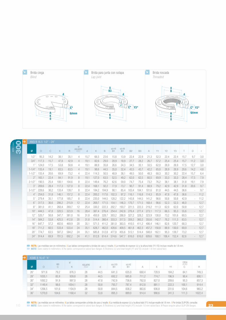
NOTA: Las medidas son en milímetros. I Las tablas corresponden a bridas de cara c/ resalte. I La medida de espesor (c) y la altura total (Y1-Y2) incluye resalte de 1.6 mm.NOTE: Sizes stated in millimeters. I The tables correspond to raised face flanges. I Thickness (c) and total height (Y1 and Y2) include 1.6 mm raised face.
NOTA: Las medidas son en milímetros. I Las tablas corresponden a bridas de cara c/ resalte. I La medida de espesor (c) y la altura total (Y1) incluye resalte de 1.6 mm. I Por bridas SLIP-ON, consultar.NOTE: Sizes stated in millimeters. I The tables correspond to raised face flanges. I Thickness (c) and total height (Y1) include 1.6 mm raised face. I Please enquire about SLIP-ON flanges.
O
10
300
AGUJEROHOLE
N
d B1sch 40
B1sch 80
X DBR TK B2 B3 A Y2 Y3Y1 r
1/2”3/4”
1”1-1/4”1-1/2”
2”2-1/2”
3”3-1/2”
4”5”6”8”
10”12”14”16”18”20”24”
N
ASME B 16.47 “A”
26”28”30”32”34”36”
O
971,61035,11092,21149,41206,51270,0
CWN
79,285,991,998,6
101,6104,6
K
876,3939,8997,0
1054,11104,91168,4
AGUJEROHOLE
282828282832
d
44,544,547,850,850,853,8
B1sch STD
641,3692,2742,9793,7844,5895,3
B1sch XS
635,0685,8736,6787,4838,2889,0
A
660,4711,2762,0812,8863,6914,4
X
720,9774,7827,0881,1936,8990,6
Y1
184,2196,9209,6222,3231,6241,3
C
CIEGABLIND
84,190,495,3
100,1104,6111,3
R
749,3800,1857,3914,4965,2
1022,4
38,147,853,863,569,984,1
100,1117,3133,4146,1177,8206,2260,4320,5347,7425,5482,6533,4587,2701,5
14,215,717,519,120,622,425,428,430,231,835,136,641,147,850,853,857,260,563,569,9
95,3117,3124,0133,4155,4165,1190,5209,6228,6254,0279,4317,5381,0444,5520,7584,2647,7711,2774,7914,4
35,142,950,863,573,291,9
104,6127,0139,7157,2185,7215,9269,7323,9381,0412,8469,9533,4584,2692,2
44444888888
121216162020242424
15,719,119,119,122,419,122,422,422,422,422,422,425,428,431,831,835,135,135,141,1
23.629,035,844,550,563,576,292,2
104,9117,6144,5171,5222,3276,4328,7360,4411,2462,0512,8614,4
66,582,688,998,6
114,3127,0149,4168,1184,2200,2235,0269,7330,2387,4450,9514,4571,5628,7685,8812,8
3,03,03,04,86,47,97,99,79,7
11,211,212,712,712,712,712,712,712,712,712,7
9,711,212,714,215,717,519,120,6
------------
15,715,717,520,622,428,431,831,836,636,642,946,050,855,660,563,568,369,973,282,6
22,425,426,926,930,233,338,142,944,547,850,852,362,095,3
101,6111,3120,7130,0139,7152,4
22,425,426,926,930,233,338,142,944,547,850,852,362,066,573,276,282,688,995,3
106,4
52,357,262,065,068,369,976,279,281,085,998,698,6
111,3117,3130,0142,7146,1158,8162,1168,1
21,326,733,542,248,360,573,288,9
101,6114,3141,2168,4219,2273,1323,9355,6406,4457,2508,0609,6
22,928,235,143,750,062,575,491,4
104,1116,8144,5171,5222,3277,4328,2360,2411,2462,3514,4616,0
22,427,734,543,549,562,074,790,7
103,4116,1143,8170,7221,5276,4327,2359,2410,5461,8513,1616,0
13,918,924,332,438,149,259,073,785,497,2
122,2146,3193,7242,8288,9317,5363,5409,5455,6547,7
15,820,926,635,040,952,562,677,990,1
102,3128,2154,1202,7254,4303,2333,3381,0428,6477,8574,6
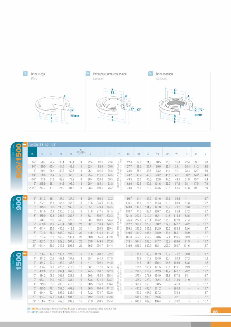
Brida ciegaBlind
6,4 mmRK0
C*
d
Brida para junta con solapa Lap joint
Brida roscada Threaded
XB3
K0
r
d
C* Y3*
6,4 mm
Y2*
XB
RK0
d
TC*
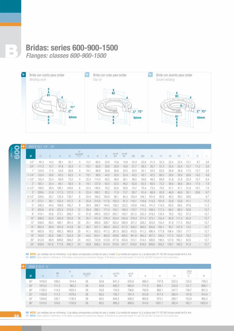
Bridas: series 600-900-1500Flanges: classes 600-900-1500
NOTA: Las medidas son en milímetros. I Las tablas corresponden a bridas de cara c/ resalte. I La medida de espesor (c) y la altura total (Y1-Y2) NO incluye resalte de 6.4 mm.NOTE: Sizes stated in millimeters. I The tables correspond to raised face flanges. I Thickness (c) and total height (Y1 and Y2) DO NOT include 6.4 mm raised face.
NOTA: Las medidas son en milímetros. I Las tablas corresponden a bridas de cara c/ resalte. I La medida de espesor (c) y la altura total (Y1-Y2) NO incluye resalte de 6.4 mm.NOTE: Sizes stated in millimeters. I The tables correspond to raised face flanges. I Thickness (c) and total height (Y1 and Y2) DO NOT include 6.4 mm raised face.
B
24
SERI
E / c
lass
Y1
ANSI B 16.5 1/2” - 24”
600
CAGUJERO
HOLE
N
d B1sch 40
Y3 DB B1sch 80
Y2RO K B2 B3 AX T r
3,03,03,04,86,47,97,99,79,7
11,211,212,712,712,712,712,712,712,712,712,7
1/2”3/4”
1”1-1/4”1-1/2”
2”2-1/2”
3”3-1/2”
4”5”6”8”
10”12”14”16”18”20”24”
N
ASME B 16.47 “A”
26”28”30”32”34”36”
O
1016,01073,21130,31193,81244,61314,5
CWN
108,0111,3114,3117,3120,7124,0
K
914,4965,2
1022,41079,51130,31193,8
AGUJEROHOLE
282828282828
d
50,853,853,860,560,566,5
B1sch STD
641,3692,2742,9793,7844,5895,3
B1sch XS
635,0685,8736,6787,4838,2889,0
A
660,4711,2762,0812,8863,6914,4
X
747,8803,1862,1917,4973,1
1031,7
Y1
222,3235,0247,7260,4269,7282,4
C
CIEGABLIND
125,5131,7139,7147,6153,9162,1
R
749,3800,1857,3914,4965,2
1022,4
38,147,853,863,569,984,1
100,1117,3133,4152,4189,0222,3273,1342,9400,1431,8495,3546,1609,6717,6
14,215,717,520,622,425,428,431,835,138,144,547,855,663,566,569,976,282,688,9
101,6
95,3117,3124,0133,4155,4165,1190,5209,6228,6273,1330,2355,6419,1508,0558,8603,3685,8743,0812,8939,8
35,142,950,863,573,292,0
104,6127,0139,7157,2185,7215,9269,7323,9381,0412,8469,9533,4584,2692,2
44444888888
121216202020202424
15,719,119,119,122,419,122,422,425,425,428,428,431,835,135,138,141,144,544,550,8
23.629,035,844,550,563,576,292,2
104,9117,6144,5171,5222,3276,4328,7360,4411,2462,0512,8614,4
66,582,688,998,6
114,3127,0149,4168,1184,2215,9266,7292,1349,3431,8489,0527,1603,3654,1723,9838,2
9,711,212,714,215,717,519,120,6
------------
15,715,717,520,622,428,431,835,139,641,147,850,857,265,069,973,277,779,282,691,9
22,425,426,928,431,836,641,146,049,353,860,566,576,2
111,3117,3127,0139,7152,4165,1184,2
22,425,426,928,431,836,641,146,049,353,860,566,576,285,991,993,7
106,4117,3127,0139,7
52,357,262,066,569,973,279,282,685,9
101,6114,3117,3133,4152,4155,4165,1177,8184,2190,5203,2
21,326,733,542,248,360,573,288,9
101,6114,3141,2168,4219,2273,1323,9355,6406,4457,2508,0609,6
22,928,235,143,750,062,575,491,4
104,1116,8144,5171,5222,3277,4328,2360,2411,2462,3514,4616,0
22,427,734,543,549,562,074,790,7
103,4116,1143,8170,7221,5276,4327,2359,2410,5461,8513,1616,0
13,918,924,332,438,149,259,073,785,497,2
122,2146,3193,7242,8288,9317,5363,5409,5455,6547,7
15,820,926,635,040,952,562,677,990,1
102,3128,2154,1202,7254,4303,2333,3381,0428,6477,8574,6
Brida con cuello para soldar Welding neck
Brida con cubo para soldar Slip on
Brida con asiento para soldar Socket welding
XAB1
d
C*
6,4 mmRK0
Y1*
XB2
RK0
6,4 mm
Y2*C*
d
XB2
B1RK0
6,4 mm
Y2*
d
C*
D
SERI
E / c
lass
1500
SEG
UN
TAB
LA D
E SC
HED
ULE
ACC
ORD
ING
TO
SC
HED
ULE
TAB
LE
SERI
E / c
lass
900
SERI
E / c
lass
B1
ANSI B 16.5 1/2” - 24”
900/1500
25NOTA: Las medidas son en milímetros. I La altura del resalte para estas series es de 6,4 mm.NOTE: Sizes stated in millimeters. I Raised face of 6.4 mm for this classes.
rO C X RAGUJERO
HOLE
N
d K B B2 B3 A Y1 Y2 Y3 T D
SEG
UN
TAB
LA D
E SC
HED
ULE
ACC
ORD
ING
TO
SC
HED
ULE
TAB
LESE
GU
N T
ABLA
DE
SCH
EDU
LEAC
CO
RDIN
G T
O
SCH
EDU
LE T
ABLE
Brida ciegaBlind
6,4 mmRK0
C*
d
Brida para junta con solapa Lap joint
Brida roscada Threaded
XB3
K0
r
d
C* Y3*
6,4 mm
Y2*
XB
RK0
d
TC*
3,03,03,04,86,47,97,9
9,711,211,212,712,712,712,712,712,712,712,712,7
9,711,211,212,712,712,712,712,712,712,712,712,7
1/2”3/4”
1”1-1/4”1-1/2”
2”2-1/2”
3”4”5”6”8”
10”12”14”16”18”20”24”
3”4”5”6”8”
10”12”14”16”18”20”24”
120,7130,0149,4158,8177,8215,9244,3
241,3292,1349,3381,0469,9546,1609,6641,4704,9787,4857,3
1041,4
266,7311,2374,7393,7482,6584,2673,1749,3825,5914,4984,3
1168,4
22,425,428,428,431,838,141,1
38,144,550,855,663,569,979,285,988,9
101,6108,0139,7
47,853,873,282,691,9
108,0124,0133,3146,1162,1177,8203,2
38,144,552,363,569,9
104,6124,0
127,0158,8190,5235,0298,5368,3419,1450,9508,0565,2622,3749,3
133,4162,1196,9228,6292,1368,3450,9495,3552,5596,9641,4762,0
35,142,950,863,573,292,0
104,6
127,0157,2185,7215,9269,7323,9381,0412,8469,9533,4584,2692,2
127,0157,2185,7215,9269,7323,9381,0412,8469,9533,4584,2692,2
4444488
888
121216202020202020
888
121212161616161616
22,422,425,425,428,425,428,4
25,431,835,131,838,138,138,141,144,550,853,866,5
31,835,141,138,144,550,853,860,566,573,279,291,9
82,688,9
101,6111,3124,0165,1190,5
190,5235,0279,4317,5393,7469,9533,4558,8616,0685,8749,3901,7
203,2241,3292,1317,5393,7482,6571,5635,0704,9774,7831,9990,6
23.629,035,844,550,563,576,2
92,2117,6144,5171,5222,3276,4328,7360,4411,2462,0512,8614,4
92,2117,6144,5171,5222,3276,4328,7360,4411,2462,0512,8614,4
22,427,734,543,249,562,074,8
90,7116,1143,8170,7221,5276,4327,2359,2410,5461,8513,1616,0
------------
22,928,235,143,750,062,575,4
91,4116,8144,5171,5222,3277,4328,2360,2411,2462,3514,4616,0
91,4116,8144,5171,5222,3277,4328,2360,2411,2462,3514,4616,0
21,326,733,542,248,360,573,2
88,9114,3141,2168,4219,2273,1323,9355,6406,4457,2508,0609,6
88,9114,3141,2168,4219,2273,1323,9355,6406,4457,2508,0609,6
60,569,973,273,282,6
101,6104,6
101,6114,3127,0139,7162,1184,2200,2212,9215,9228,6247,7292,1
117,3124,0155,4171,5212,9254,0282,4298,5311,2327,2355,6406,4
31,835,141,141,144,557,263,5
53,869,979,285,9
101,6108,0117,3130,0133,4152,4158,8203,2
73,290,4
104,6119,1142,7158,8180,8
-----
31,835,141,141,144,557,263,5
53,869,979,285,9
114,3127,0142,7155,4165,1190,5209,6266,7
73,290,4
104,6119,1142,7177,8218,9241,3260,4276,4292,1330,2
22,425,428,430,231,838,147,8
41,147,853,857,263,571,476,282,685,988,991,9
101,6
50,857,263,569,976,284,191,9
-----
9,711,212,714,215,717,519,1
------------
------------
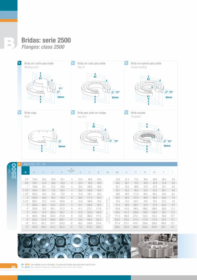
Bridas: serie 2500Flanges: class 2500
Brida con cuello para soldar Welding neck
Brida con cubo para soldar Slip on
Brida con asiento para soldar Socket welding
XAB1
d
C*
6,4 mmRK0
Y1*
XB2
RK0
6,4 mm
Y2*C*
d
XB2
B1RK0
6,4 mm
Y2*
d
C*
D
B
26NOTA: Las medidas son en milímetros. I La altura del resalte para esta serie es de 6,4 mm.NOTE: Sizes stated in millimeters. I Raised face of 6.4 mm for this classes.
Brida ciegaBlind
6,4 mmRK0
C*
d
Brida para junta con solapa Lap joint
Brida roscada Threaded
XB3
K0
r
d
C* Y3*
6,4 mm
Y2*
XB
RK0
d
TC*
SERI
E / c
lass
B1
ANSI B 16.5 1/2” - 12”
2500
rO C X RAGUJERO
HOLE
N
d K B B3 A Y1 Y2 Y3 T
SEG
UN
TAB
LA D
E SC
HED
ULE
ACC
ORD
ING
TO
SC
HED
ULE
TAB
LE
22,422,425,428,431,828,431,835,141,147,853,853,866,573,2
35,142,950,863,573,292,0
104,6127,0157,2185,7215,9269,7323,9381,0
44444888888
121212
42,950,857,273,279,295,3
114,3133,4165,1203,2235,0304,8374,7441,5
30,231,835,138,144,550,857,266,576,291,9
108,0127,0165,1184,2
133,4139,7158,8184,2203,2235,0266,7304,8355,6419,1482,6552,5673,1762,0
1/2”3/4”
1”1-1/4”1-1/2”
2”2-1/2”
3”4”5”6”8”
10”12”
3,03,03,04,86,47,97,99,7
11,211,212,712,712,712,7
28,431,835,138,144,550,857,263,569,976,282,695,3
108,0120,7
21,326,733,542,248,360,573,288,9
114,3141,2168,4219,2273,1323,9
39,642,947,852,360,569,979,291,9
108,0130,0152,4177,8228,6254,0
39,642,947,852,360,569,979,291,9
108,0130,0152,4177,8228,6254,0
73,279,288,995,3
111,3127,0142,7168,1190,5228,6273,1317,5419,1463,6
22,928,235,143,750,062,575,491,4
116,8144,5171,5222,3277,4328,2
23,629,035,844,550,563,576,292,2
117,6144,5171,5222,3276,4328,7
88,995,3
108,0130,0146,1171,5196,9228,6273,1323,9368,3438,2539,8619,3
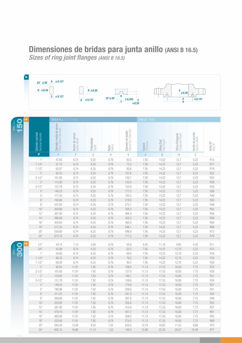
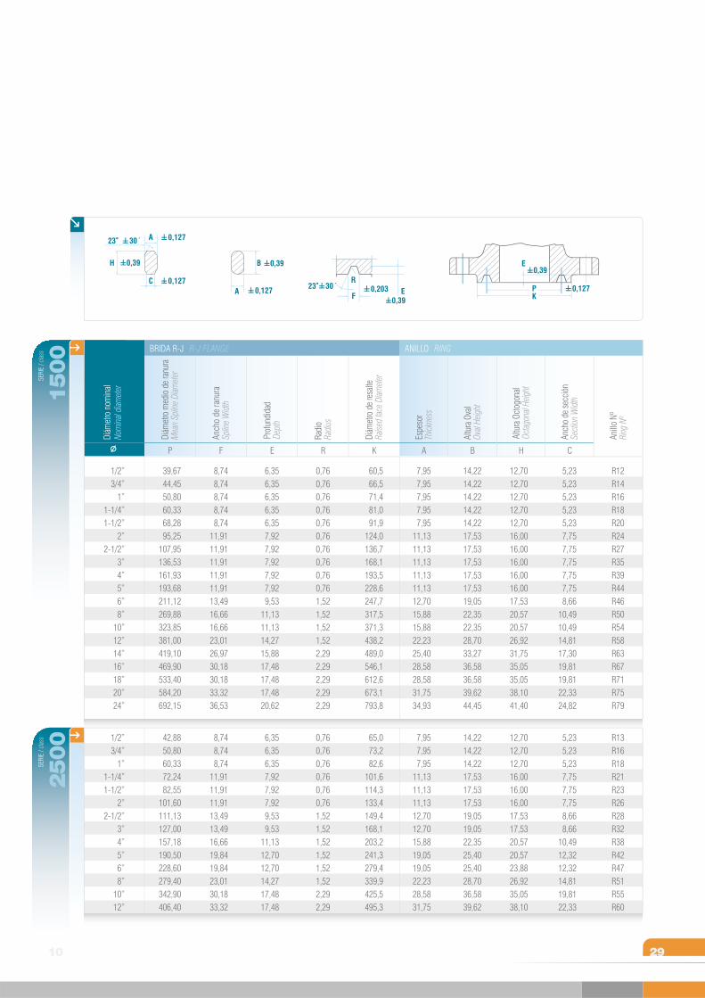
Dimensiones de bridas para junta anillo (ANSI B 16.5)Sizes of ring joint flanges (ANSI B 16.5)
1/2”3/4”
1”1-1/4”1-1/2”
2”2-1/2”
3”3-1/2”
4”5”6”8”
10”12”14”16”18”20”24”
34,1442,8850,8060,3368,2882,55
101,60123,83131,78149,23180,98211,25269,88323,85381,00419,10469,90533,40584,20692,15
R11R13R16R18R20R23R26R31R34R37R41R45R49R53R57R61R65R69R73R77
7,148,748,748,748,74
11,9111,9111,9111,9111,9111,9111,9111,9111,9111,9111,9111,9111,9113,4916,66
5,566,356,356,356,357,927,927,927,927,927,927,927,927,927,927,927,927,929,53
11,13
6,357,957,957,957,95
11,1311,1311,1311,1311,1311,1311,1311,1311,1311,1311,1311,1311,1312,7015,88
0,760,760,760,760,760,760,760,760,760,760,760,760,760,760,760,760,760,761,521,52
50,863,569,979,290,4
108,0127,0146,1158,8174,8209,6241,3301,8355,6412,8457,2508,0574,5635,0749,3
11,1814,2214,2214,2214,2217,5317,5317,5317,5317,5317,5317,5317,5317,5317,5317,5317,5317,5319,0522,35
9,6512,7012,7012,7012,7016,0016,0016,0016,0016,0016,0016,0016,0016,0016,0016,0016,0016,0017,5320,57
4,325,235,235,235,237,757,757,757,757,757,757,757,757,757,757,757,757,758,66
10,49
0,127
0,127
C
A
H 0,39
23 30´
0,127A
B 0,39
PK
E
0,127
0,39
0,39E
F
R23 30´ 0,203
10
SERI
E / c
lass
150
SERI
E / c
lass
300
1”1-1/4”1-1/2”
2”2-1/2”
3”3-1/2”
4”5”6”8”
10”12”14”16”18”20”24”
A B H C
Nom
inal d
iamet
erDi
ámet
ro n
omin
al
Diám
etro
med
io d
e ra
nura
Mea
n Sp
line
Diam
eter
Anch
o de
ranu
raSp
line
Wid
th
Prof
undi
dad
Dept
h
Radi
oRa
dius
Diám
etro
de
resa
lteRa
ised
face
Diam
eter
Espe
sor
Thick
ness
Altu
ra O
val
Oval
Heig
ht
Altu
ra O
ctog
onal
Octag
onal
Heig
ht
Anch
o de
secc
ión
Secti
on W
idth
Anill
o Nº
Ring
Nº
ANILLO RINGBRIDA R-J R-J FLANGE
P F E R K
47,6357,1565,0782,55
101,60114,30131,78149,23171,45193,68247,65304,80381,00396,68454,03517,53558,80673,10
R15R17R19R22R25R29R33R36R40R43R48R52R56R59R64R68R72R76
8,748,748,748,748,748,748,748,748,748,748,748,748,748,748,748,748,748,74
6,356,356,356,356,356,356,356,356,356,356,356,356,356,356,356,356,356,35
7,957,957,957,957,957,957,957,957,957,957,957,957,957,957,957,957,957,95
0,760,760,760,760,760,760,760,760,760,760,760,760,760,760,760,760,760,76
63,573,282,6
101,6120,7133,4153,9171,5193,5218,9273,1330,2406,4425,5482,6546,1596,9711,2
14,2214,2214,2214,2214,2214,2214,2214,2214,2214,2214,2214,2214,2214,2214,2214,2214,2214,22
12,712,712,712,712,712,712,712,712,712,712,712,712,712,712,712,712,712,7
5,235,235,235,235,235,235,235,235,235,235,235,235,235,235,235,235,235,23
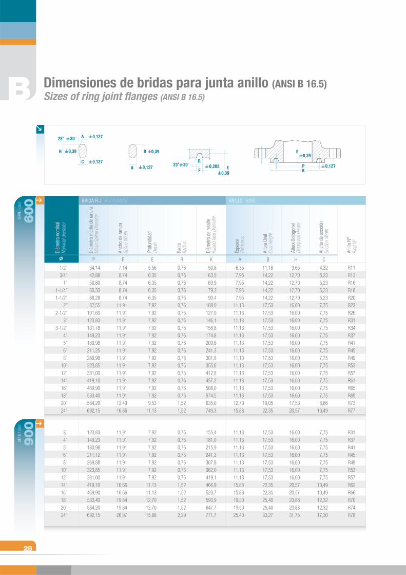
Dimensiones de bridas para junta anillo (ANSI B 16.5)Sizes of ring joint flanges (ANSI B 16.5)
0,127
0,127
C
A
H 0,39
23 30´
0,127A
B 0,39
PK
E
0,127
0,39
0,39E
F
R23 30´ 0,203
SERI
E / c
lass
600
SERI
E / c
lass
900
A B H C
Nom
inal d
iamet
erDi
ámet
ro n
omin
al
Diám
etro
med
io d
e ra
nura
Mea
n Sp
line
Diam
eter
Anch
o de
ranu
raSp
line
Wid
th
Prof
undi
dad
Dept
h
Radi
oRa
dius
Diám
etro
de
resa
lteRa
ised
face
Diam
eter
Espe
sor
Thick
ness
Altu
ra O
val
Oval
Heig
ht
Altu
ra O
ctog
onal
Octag
onal
Heig
ht
Anch
o de
secc
ión
Secti
on W
idth
Anill
o Nº
Ring
Nº
ANILLO RINGBRIDA R-J R-J FLANGE
P F E R K
B
28
34,1442,8850,8060,3368,2882,55
101,60123,83131,78149,23180,98211,25269,98323,85381,00419,10469,90533,40584,20692,15
R11R13R16R18R20R23R26R31R34R37R41R45R49R53R57R61R65R69R73R77
7,148,748,748,748,74
11,9111,9111,9111,9111,9111,9111,9111,9111,9111,9111,9111,9111,9113,4916,66
5,566,356,356,356,357,927,927,927,927,927,927,927,927,927,927,927,927,929,53
11,13
6,357,957,957,957,95
11,1311,1311,1311,1311,1311,1311,1311,1311,1311,1311,1311,1311,1312,7015,88
0,760,760,760,760,760,760,760,760,760,760,760,760,760,760,760,760,760,761,521,52
50,863,569,979,290,4
108,0127,0146,1158,8174,8209,6241,3301,8355,6412,8457,2508,0574,5635,0749,3
11,1814,2214,2214,2214,2217,5317,5317,5317,5317,5317,5317,5317,5317,5317,5317,5317,5317,5319,0522,35
9,6512,7012,7012,7012,7016,0016,0016,0016,0016,0016,0016,0016,0016,0016,0016,0016,0016,0017,5320,57
4,325,235,235,235,237,757,757,757,757,757,757,757,757,757,757,757,757,758,66
10,49
1/2”3/4”
1”1-1/4”1-1/2”
2”2-1/2”
3”3-1/2”
4”5”6”8”
10”12”14”16”18”20”24”
3”4”5”6”8”
10”12”14”16”18”20”24”
123,83149,23180,98211,12269,88323,85381,00419,10469,90533,40584,20692,15
R31R37R41R45R49R53R57R62R66R70R74R78
11,9111,9111,9111,9111,9111,9111,9116,6616,6619,8419,8426,97
7,927,927,927,927,927,927,92
11,1311,1312,7012,7015,88
11,1311,1311,1311,1311,1311,1311,1315,8815,8819,5019,5025,40
0,760,760,760,760,760,760,761,521,521,521,522,29
155,4181,0215,9241,3307,8362,0419,1466,9523,7593,9647,7771,7
17,5317,5317,5317,5317,5317,5317,5322,3522,3525,4025,4033,27
16,0016,0016,0016,0016,0016,0016,0020,5720,5723,8823,8831,75
7,757,757,757,757,757,757,75
10,4910,4912,3212,3217,30
0,127
0,127
C
A
H 0,39
23 30´
0,127A
B 0,39
PK
E
0,127
0,39
0,39E
F
R23 30´ 0,203
2910
SERI
E / c
lass
1500
SERI
E / c
lass
2500
A B H C
Nom
inal d
iamet
erDi
ámet
ro n
omin
al
Diám
etro
med
io d
e ra
nura
Mea
n Sp
line
Diam
eter
Anch
o de
ranu
raSp
line
Wid
th
Prof
undi
dad
Dept
h
Radi
oRa
dius
Diám
etro
de
resa
lteRa
ised
face
Diam
eter
Espe
sor
Thick
ness
Altu
ra O
val
Oval
Heig
ht
Altu
ra O
ctog
onal
Octag
onal
Heig
ht
Anch
o de
secc
ión
Secti
on W
idth
Anill
o Nº
Ring
Nº
ANILLO RINGBRIDA R-J R-J FLANGE
P F E R K
1/2”3/4”
1”1-1/4”1-1/2”
2”2-1/2”
3”4”5”6”8”
10”12”14”16”18”20”24”
39,6744,4550,8060,3368,2895,25
107,95136,53161,93193,68211,12269,88323,85381,00419,10469,90533,40584,20692,15
R12R14R16R18R20R24R27R35R39R44R46R50R54R58R63R67R71R75R79
8,748,748,748,748,74
11,9111,9111,9111,9111,9113,4916,6616,6623,0126,9730,1830,1833,3236,53
6,356,356,356,356,357,927,927,927,927,929,53
11,1311,1314,2715,8817,4817,4817,4820,62
7,957,957,957,957,95
11,1311,1311,1311,1311,1312,7015,8815,8822,2325,4028,5828,5831,7534,93
0,760,760,760,760,760,760,760,760,760,761,521,521,521,522,292,292,292,292,29
60,566,571,481,091,9
124,0136,7168,1193,5228,6247,7317,5371,3438,2489,0546,1612,6673,1793,8
14,2214,2214,2214,2214,2217,5317,5317,5317,5317,5319,0522,3522,3528,7033,2736,5836,5839,6244,45
12,7012,7012,7012,7012,7016,0016,0016,0016,0016,0017,5320,5720,5726,9231,7535,0535,0538,1041,40
5,235,235,235,235,237,757,757,757,757,758,66
10,4910,4914,8117,3019,8119,8122,3324,82
1/2”3/4”
1”1-1/4”1-1/2”
2”2-1/2”
3”4”5”6”8”
10”12”
42,8850,8060,3372,2482,55
101,60111,13127,00157,18190,50228,60279,40342,90406,40
R13R16R18R21R23R26R28R32R38R42R47R51R55R60
8,748,748,74
11,9111,9111,9113,4913,4916,6619,8419,8423,0130,1833,32
6,356,356,357,927,927,929,539,53
11,1312,7012,7014,2717,4817,48
7,957,957,95
11,1311,1311,1312,7012,7015,8819,0519,0522,2328,5831,75
0,760,760,760,760,760,761,521,521,521,521,521,522,292,29
65,073,282,6
101,6114,3133,4149,4168,1203,2241,3279,4339,9425,5495,3
14,2214,2214,2217,5317,5317,5319,0519,0522,3525,4025,4028,7036,5839,62
12,7012,7012,7016,0016,0016,0017,5317,5320,5720,5723,8826,9235,0538,10
5,235,235,237,757,757,758,668,66
10,4912,3212,3214,8119,8122,33
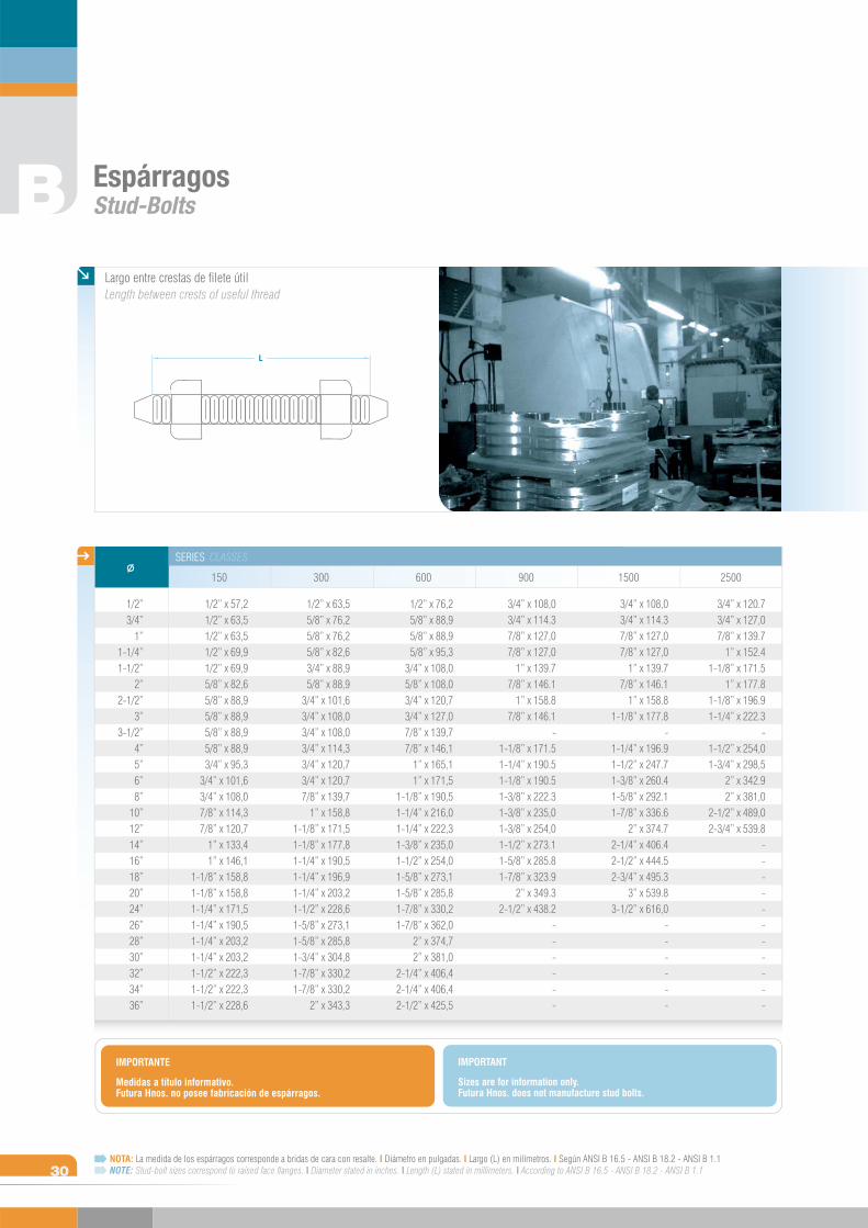
NOTA: La medida de los espárragos corresponde a bridas de cara con resalte. I Diámetro en pulgadas. I Largo (L) en milímetros. I Según ANSI B 16.5 - ANSI B 18.2 - ANSI B 1.1NOTE: Stud-bolt sizes correspond to raised face flanges. I Diameter stated in inches. I Length (L) stated in millimeters. I According to ANSI B 16.5 - ANSI B 18.2 - ANSI B 1.1
EspárragosStud-Bolts
Largo entre crestas de filete útilLength between crests of useful thread
SERIES CLASSES
150 300 600 900 1500 2500
B
30
3/4” x 108,03/4” x 114.37/8” x 127,07/8” x 127,0
1” x 139.77/8” x 146.1
1” x 158.81-1/8” x 177.8
-1-1/4” x 196.91-1/2” x 247.71-3/8” x 260.41-5/8” x 292.11-7/8” x 336.6
2” x 374.72-1/4” x 406.42-1/2” x 444.52-3/4” x 495.3
3” x 539.83-1/2” x 616,0
------
3/4” x 108,03/4” x 114.37/8” x 127,07/8” x 127,0
1” x 139.77/8” x 146.1
1” x 158.87/8” x 146.1
-1-1/8” x 171.51-1/4” x 190.51-1/8” x 190.51-3/8” x 222.31-3/8” x 235,01-3/8” x 254,01-1/2” x 273.11-5/8” x 285.81-7/8” x 323.9
2” x 349.32-1/2” x 438.2
------
3/4” x 120.73/4” x 127,07/8” x 139.7
1” x 152.41-1/8” x 171.5
1” x 177.81-1/8” x 196.91-1/4” x 222.3
-1-1/2” x 254,01-3/4” x 298,5
2” x 342.92” x 381,0
2-1/2” x 489,02-3/4” x 539.8
-----------
1/2”3/4”
1”1-1/4”1-1/2”
2”2-1/2”
3”3-1/2”
4”5”6”8”
10”12”14”16”18”20”24”26”28”30”32”34”36”
1/2” x 57,21/2” x 63,51/2” x 63,51/2” x 69,91/2” x 69,95/8” x 82,65/8” x 88,95/8” x 88,95/8” x 88,95/8” x 88,93/4” x 95,3
3/4” x 101,63/4” x 108,07/8” x 114,37/8” x 120,7
1” x 133,41” x 146,1
1-1/8” x 158,81-1/8” x 158,81-1/4” x 171,51-1/4” x 190,51-1/4” x 203,21-1/4” x 203,21-1/2” x 222,31-1/2” x 222,31-1/2” x 228,6
1/2” x 63,55/8” x 76,25/8” x 76,25/8” x 82,63/4” x 88,95/8” x 88,9
3/4” x 101,63/4” x 108,03/4” x 108,03/4” x 114,33/4” x 120,73/4” x 120,77/8” x 139,7
1” x 158,81-1/8” x 171,51-1/8” x 177,81-1/4” x 190,51-1/4” x 196,91-1/4” x 203,21-1/2” x 228,61-5/8” x 273,11-5/8” x 285,81-3/4” x 304,81-7/8” x 330,21-7/8” x 330,2
2” x 343,3
1/2” x 76,25/8” x 88,95/8” x 88,95/8” x 95,3
3/4” x 108,05/8” x 108,03/4” x 120,73/4” x 127,07/8” x 139,77/8” x 146,1
1” x 165,11” x 171,5
1-1/8” x 190,51-1/4” x 216,01-1/4” x 222,31-3/8” x 235,01-1/2” x 254,01-5/8” x 273,11-5/8” x 285,81-7/8” x 330,21-7/8” x 362,0
2” x 374,72” x 381,0
2-1/4” x 406,42-1/4” x 406,42-1/2” x 425,5
Medidas a título informativo. Futura Hnos. no posee fabricación de espárragos.
IMPORTANTE
Sizes are for information only. Futura Hnos. does not manufacture stud bolts.
IMPORTANT
Accesorios de DerivaciónBranch Fittings
AD
SCH 80
WELDINSERT
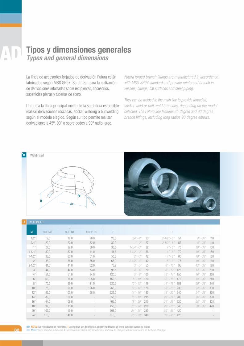
NOTA: Las medidas son en milímetros. I Las medidas son de referencia, pueden modificarse sin previo aviso por razones de diseño. NOTE: Sizes stated in millimeters. I Dimensions are stated only for reference and may be changed without prior notice on the basis of design.
SCH 40 SCH 160 F R
D
1/2”3/4”
1”1-1/4”1-1/2”
2”2-1/2”
3”4”6”8”
10”12”14”16”18”20”24”
Weldinsert
Tipos y dimensiones generalesTypes and general dimensions
Futura forged branch fittings are manufactured in accordance with MSS SP97 standard and provide reinforced branch in vessels, fittings, flat surfaces and steel piping.
They can be welded to the main line to provide threaded, socket-weld or butt-weld branches, depending on the model selected. The Futura line features 45 degree and 90 degree branch fittings, including long radius 90 degree elbows.
La línea de accesorios forjados de derivación Futura están fabricados según MSS SP97. Se utilizan para la realización de derivaciones reforzadas sobre recipientes, accesorios, superficies planas y tuberías de acero.
Unidos a la línea principal mediante la soldadura es posible realizar derivaciones roscadas, socket-welding o buttwelding según el modelo elegido. Según su tipo permite realizar derivaciones a 45º, 90º o sobre codos a 90º radio largo.
3/4” - 2”1” - 2”
1-1/4” - 3”1-1/2” - 3”
2” - 3”2-1/2” - 4”
3” - 5”4” - 6”5” - 8”
8” - 10”10” - 12”12” - 14”14” - 16”16” - 18”18” - 20”20” - 24”24” - 28”26” - 28”
2327323842425570
100120146178190215240280330340
23,830,236,544,550,865,076,293,5
120,6169,8220,6266,0325,0355,0405,0455,0508,0610,0
28,032,038,044,051,055,062,073,084,0
105,0111,0126,0158,0
-----
19,022,027,032,033,038,041,044,051,078,099,094,0
103,0100,0106,0111,0119,0140,0
19,022,027,032,033,038,041,044,051,066,070,078,086,089,094,097,0
102,0116,0
2-1/2” - 6”2-1/2“ - 6”
4” - 8”4” - 8”4” - 8”5” - 8”
6” - 10”8“ - 12”
10” - 14”12” - 16”14” - 18”16” - 20”18” - 20”20” - 24”24” - 26”26” - 28”30” - 36”30” - 36”
57577070807595
125150175183230240280320340420420
8“ - 36”8” - 36”
10” - 36”10” - 36”10” - 36”10” - 36”12” - 36”14” - 36”16” - 36”18” - 36”20” - 36”24” - 36”24” - 36”26” - 36”28” - 36”30” - 36”
110110130150160160180210220240240330330390405420
--
DF
R
AD
32
SERI
E / c
lass
6000
33NOTA: Las medidas son en milímetros. I Las medidas son de referencia, pueden modificarse sin previo aviso por razones de diseño. NOTE: Sizes stated in millimeters. I Dimensions are stated only for reference and may be changed without prior notice on the basis of design.
Sockinsert Threadinsert
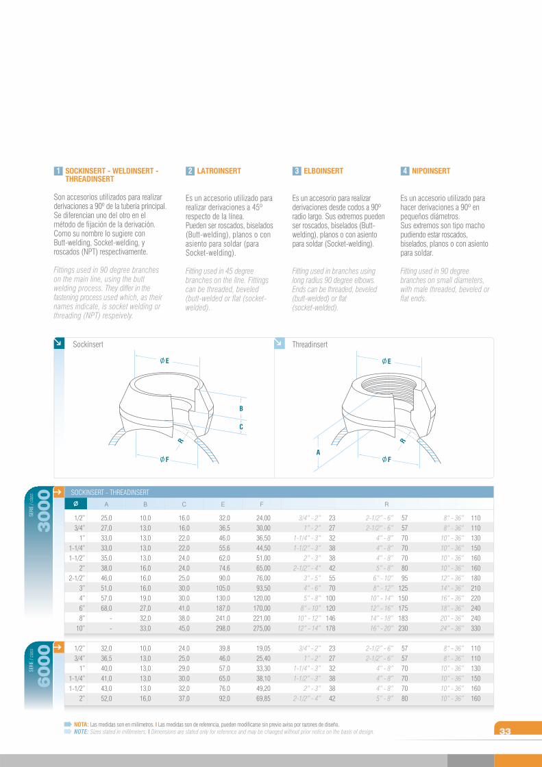
1 2 SOCKINSERT - WELDINSERT - THREADINSERT
Son accesorios utilizados para realizar derivaciones a 90º de la tubería principal. Se diferencian uno del otro en el método de fijación de la derivación. Como su nombre lo sugiere con Butt-welding, Socket-welding, y roscados (NPT) respectivamente.
Fittings used in 90 degree branches on the main line, using the butt welding process. They differ in the fastening process used which, as their names indicate, is socket welding or threading (NPT) respeively.
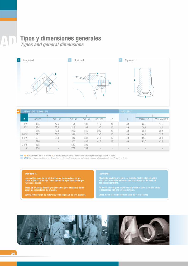
LATROINSERT
Es un accesorio utilizado para realizar derivaciones a 45º respecto de la línea. Pueden ser roscados, biselados (Butt-welding), planos o con asiento para soldar (para Socket-welding).
Fitting used in 45 degree branches on the line. Fittings can be threaded, beveled (butt-welded or flat (socket-welded).
3 ELBOINSERT
Es un accesorio para realizar derivaciones desde codos a 90º radio largo. Sus extremos pueden ser roscados, biselados (Butt- welding), planos o con asiento para soldar (Socket-welding).
Fitting used in branches using long radius 90 degree elbows. Ends can be threaded, beveled (butt-welded) or flat (socket-welded).
4 NIPOINSERT
Es un accesorio utilizado para hacer derivaciones a 90º en pequeños diámetros. Sus extremos son tipo macho pudiendo estar roscados, biselados, planos o con asiento para soldar.
Fitting used in 90 degree branches on small diameters, with male threaded, beveled or flat ends.
SERI
E / c
lass SOCKINSERT - THREADINSERT
3000
R
3/4” - 2”1” - 2”
1-1/4” - 3”1-1/2” - 3”
2” - 3”2-1/2” - 4”
3” - 5”4” - 6”5” - 8”
8” - 10”10” - 12”12” - 14”
3/4” - 2”1” - 2”
1-1/4” - 3”1-1/2” - 3”
2” - 3”2-1/2” - 4”
2327323838425570
100120146178
232732383842
2-1/2” - 6”2-1/2“ - 6”
4” - 8”4” - 8”4” - 8”5” - 8”
6” - 10”8“ - 12”
10” - 14”12” - 16”14” - 18”16” - 20”
2-1/2” - 6”2-1/2“ - 6”
4” - 8”4” - 8”4” - 8”5” - 8”
57577070708095
125150175183230
575770707080
8“ - 36”8” - 36”
10” - 36”10” - 36”10” - 36”10” - 36”12” - 36”14” - 36”16” - 36”18” - 36”20” - 36”24” - 36”
8“ - 36”8” - 36”
10” - 36”10” - 36”10” - 36”10” - 36”
110110130150160160180210220240240330
110110130150160160
F
24,0030,0036,5044,5051,0065,0076,0093,50
120,00170,00221,00275,00
19,0525,4033,3038,1049,2069,85
C
16,016,022,022,024,024,025,030,030,041,038,045,0
24,025,029,030,032,037,0
E
32,036,546,055,662,074,690,0
105,0130,0187,0241,0298,0
39,846,057,065,076,092,0
B
10,013,013,013,013,016,016,016,019,027,032,033,0
10,013,013,013,013,016,0
A
25,027,033,033,035,038,046,051,057,068,0
--
32,036,540,041,043,052,0
1/2”3/4”
1”1-1/4”1-1/2”
2”2-1/2”
3”4”6”8”
10”
1/2”3/4”
1”1-1/4”1-1/2”
2”
AF
RB
F
C
E
R
E
AD
34
NOTA: Las medidas son en milímetros. I Las medidas son de referencia, pueden modificarse sin previo aviso por razones de diseño. NOTE: Sizes stated in millimeters. I Dimensions are stated only for reference and may be changed without prior notice on the basis of design.
Las medidas estandar de fabricación son las descriptas en las tablas adjuntas las cuales son de referencia y pueden cambiar por razones de diseño.
Todas las piezas se diseñan y/o fabrican en otras medidas y series según las necesidades del proyecto.
Ver especificaciones de materiales en la página 20 de éste catálogo.
IMPORTANTE
Standard manufacturing sizes are described in the attached tables, which are provided for reference and may change on the basis of design considerations.
All pieces are designed and/or manufactured in other sizes and series in accordance with project requirements.
Check material specifications on page 20 of this catalog.
IMPORTANT
Tipos y dimensiones generalesTypes and general dimensions
A
B
C
A
B
C
A
B
SCH 80
LATROINSERT - ELBOINSERT NIPOINSERT
SCH 160 SCH 80SCH 40 SCH 160 C
A B B
1/2”3/4”
1”1-1/4”1-1/2”
2”2-1/2”
3”
Latroinsert Elboinsert Nipoinsert
11,715,520,729,534,042,8
--
15,821,024,335,040,952,562,777,9
47,655,660,366,781,0
---
40,548,655,662,766,781,086,596,0
A
898989898989
--
SCH 160 / XXS
14,219,125,433,338,142,9
--
SCH 80 / XS
23,830,136,544,450,865,0
--
101313131316
--
13,818,924,332,538,149,259,073,7

Figuras 8Figures 8 Blanks
F8
F8
36
A
W
*
O
t*Wt*
* Ver Notas / See Notes
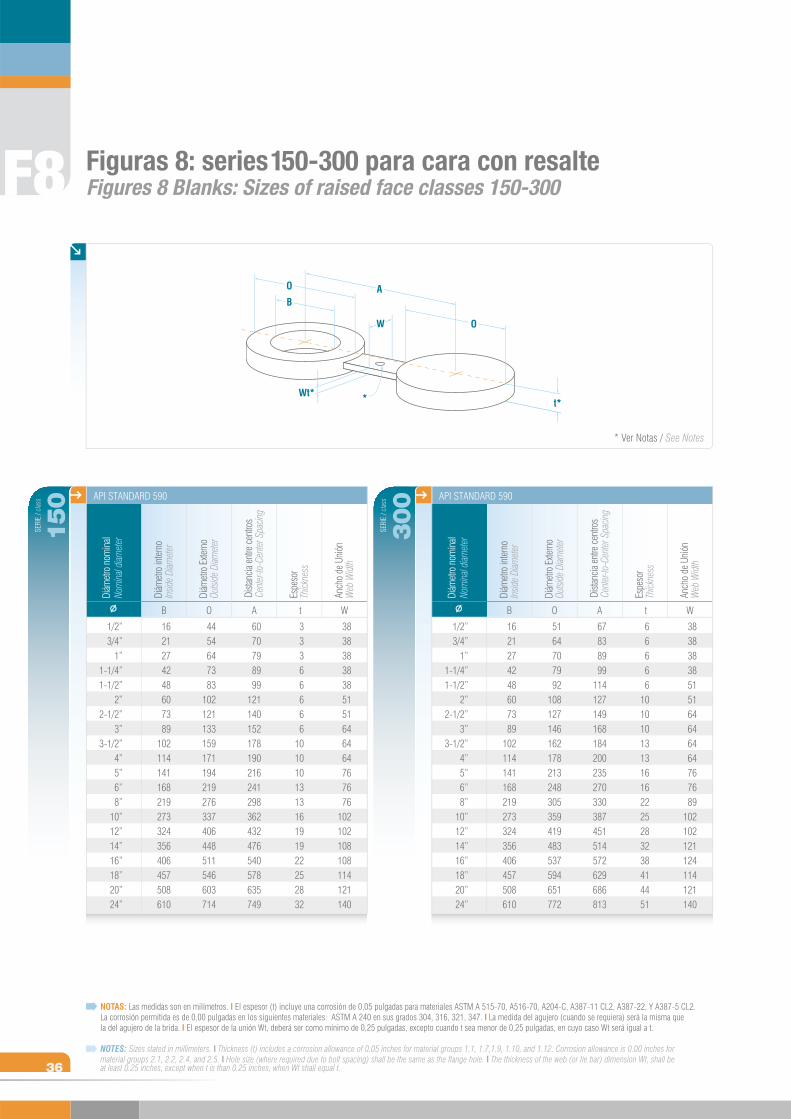
Figuras 8: series 150-300 para cara con resalte Figures 8 Blanks: Sizes of raised face classes 150-300
1/2” 3/4”
1”1-1/4”1-1/2”
2”2-1/2”
3”3-1/2”
4”5”6”8”
10”12”14”16”18”20”24”
SERI
E / c
lass
150
Nom
inal d
iamet
erDi
ámet
ro n
omin
al
API STANDARD 590
Diám
etro
inte
rno
Insid
e Di
amet
er
B
1621274248607389
102114141168219273324356406457508610
Diám
etro
Exte
rno
Outsi
de D
iamet
er
O
4454647383
102121133159171194219276337406448511546603714
Dista
ncia
entre
cen
tros
Cent
er-to
-Cen
ter S
pacin
g
A
6070798999
121140152178190216241298362432476540578635749
Espe
sor
Thick
ness
t
33366666
101010131316191922252832
Anch
o de
Uni
ónW
eb W
idth
W
38383838385151646464767676
102102108108114121140
1/2” 3/4”
1”1-1/4”1-1/2”
2”2-1/2”
3”3-1/2”
4”5”6”8”
10”12”14”16”18”20”24”
SERI
E / c
lass
300
Nom
inal d
iamet
erDi
ámet
ro n
omin
al
API STANDARD 590Di
ámet
ro in
tern
oIn
side
Diam
eter
B
Diám
etro
Exte
rno
Outsi
de D
iamet
er
O
Dista
ncia
entre
cen
tros
Cent
er-to
-Cen
ter S
pacin
gA
Espe
sor
Thick
ness
t
Anch
o de
Uni
ónW
eb W
idth
W
1621274248607389
102114141168219273324356406457508610
5164707992
108127146162178213248305359419483537594651772
67838999
114127149168184200235270330387451514572629686813
66666
101010131316162225283238414451
38383838515164646464767689
102102121124114121140
O
B
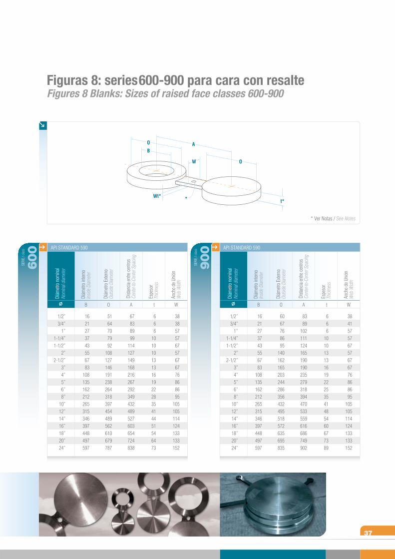
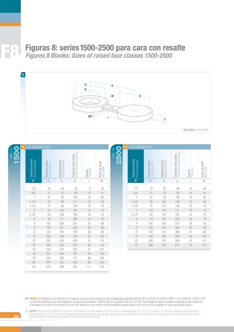
NOTAS: Las medidas son en milímetros. I El espesor (t) incluye una corrosión de 0,05 pulgadas para materiales ASTM A 515-70, A516-70, A204-C, A387-11 CL2, A387-22, Y A387-5 CL2. La corrosión permitida es de 0,00 pulgadas en los siguientes materiales: ASTM A 240 en sus grados 304, 316, 321, 347. I La medida del agujero (cuando se requiera) será la misma que la del agujero de la brida. I El espesor de la unión Wt, deberá ser como mínimo de 0,25 pulgadas, excepto cuando t sea menor de 0,25 pulgadas, en cuyo caso Wt será igual a t.
NOTES: Sizes stated in millimeters. I Thickness (t) includes a corrosion allowance of 0.05 inches for material groups 1.1, 1.7,1.9, 1.10, and 1.12. Corrosion allowance is 0.00 inches for material groups 2.1, 2.2, 2.4, and 2.5. I Hole size (where required due to bolt spacing) shall be the same as the flange hole. I The thickness of the web (or tie bar) dimension Wt, shall be at least 0.25 inches, except when t is than 0.25 inches, when Wt shall equal t.
37
Figuras 8: series 600-900 para cara con resalte Figures 8 Blanks: Sizes of raised face classes 600-900
1/2” 3/4”
1”1-1/4”1-1/2”
2”2-1/2”
3”4”5”6”8”
10”12”14”16”18”20”24”
SERI
E / c
lass
600
Nom
inal d
iamet
erDi
ámet
ro n
omin
al
API STANDARD 590
Diám
etro
inte
rno
Insid
e Di
amet
er
B
Diám
etro
Exte
rno
Outsi
de D
iamet
er
O
Dista
ncia
entre
cen
tros
Cent
er-to
-Cen
ter S
pacin
g
A
Espe
sor
Thick
ness
t
Anch
o de
Uni
ónW
eb W
idth
W
1/2” 3/4”
1”1-1/4”1-1/2”
2”2-1/2”
3”4”5”6”8”
10”12”14”16”18”20”24”
SERI
E / c
lass
900
Nom
inal d
iamet
erDi
ámet
ro n
omin
al
API STANDARD 590
Diám
etro
inte
rno
Insid
e Di
amet
er
B
Diám
etro
Exte
rno
Outsi
de D
iamet
er
ODi
stanc
ia en
tre c
entro
sCe
nter-
to-C
ente
r Spa
cingA
Espe
sor
Thick
ness
t
Anch
o de
Uni
ónW
eb W
idth
W
67838999
114127149168216267292349432489527603654724838
666
10101013131619222835414451546473
383857576757676776868695
105105114124133133152
1621273743556783
108135162212265315346397448497597
5164707992
108127146191238264318397454489562610679787
1621273743556783
108135162212265315346397448497597
6067768695
140162165203244286356432495518572635695835
8389
102111124165190190235279318394470533559616686749902
666
10101313161922253541485460677389
384157576757676776868695
105105114124133133152
A
W
*
O
t*Wt*
* Ver Notas / See Notes
O
B
38
F8 Figuras 8: series 1500-2500 para cara con resalte Figures 8 Blanks: Sizes of raised face classes 1500-2500
1/2” 3/4”
1”1-1/4”1-1/2”
2”2-1/2”
3”4”5”6”8”
10”12”14”16”18”20”24”
SERI
E / c
lass
1500
Nom
inal d
iamet
erDi
ámet
ro n
omin
al
API STANDARD 590
Diám
etro
inte
rno
Insid
e Di
amet
er
B
Diám
etro
Exte
rno
Outsi
de D
iamet
er
O
Dista
ncia
entre
cen
tros
Cent
er-to
-Cen
ter S
pacin
g
A
Espe
sor
Thick
ness
t
Anch
o de
Uni
ónW
eb W
idth
W
1/2” 3/4”
1”1-1/4”1-1/2”
2”2-1/2”
3”4”5”6”8”
10”12”
SERI
E / c
lass
2500
Nom
inal d
iamet
erDi
ámet
ro n
omin
al
API STANDARD 590Di
ámet
ro in
tern
oIn
side
Diam
eter
B
Diám
etro
Exte
rno
Outsi
de D
iamet
er
O
Dista
ncia
entre
cen
tros
Cent
er-to
-Cen
ter S
pacin
gA
Espe
sor
Thick
ness
t
Anch
o de
Uni
ónW
eb W
idth
W
1621273541536378
102128154198248289
677383
102114143165194232276314384473546
8995
108130146171197229273324368438540619
1010101316161922283541546779
3841646470707676898989
102114114
1621273541536378
102128154203255303333381429478575
6067768695
140162171206251279349432518575638702752899
8389
102111124165190203241292318394483572635705775832991
61010101313161922283841516067768695
111
3841646470707676898989
102114114127133146152178
A
W
*
O
t*Wt*
* Ver Notas / See Notes
O
B
NOTAS: Las medidas son en milímetros. I El espesor (t) incluye una corrosión de 0,05 pulgadas para materiales ASTM A 515-70, A516-70, A204-C, A387-11 CL2, A387-22, Y A387-5 CL2. La corrosión permitida es de 0,00 pulgadas en los siguientes materiales: ASTM A 240 en sus grados 304, 316, 321, 347. I La medida del agujero (cuando se requiera) será la misma que la del agujero de la brida. I El espesor de la unión Wt, deberá ser como mínimo de 0,25 pulgadas, excepto cuando t sea menor de 0,25 pulgadas, en cuyo caso Wt será igual a t.
NOTES: Sizes stated in millimeters. I Thickness (t) includes a corrosion allowance of 0.05 inches for material groups 1.1, 1.7,1.9, 1.10, and 1.12. Corrosion allowance is 0.00 inches for material groups 2.1, 2.2, 2.4, and 2.5. I Hole size (where required due to bolt spacing) shall be the same as the flange hole. I The thickness of the web (or tie bar) dimension Wt, shall be at least 0.25 inches, except when t is than 0.25 inches, when Wt shall equal t.
F
Forja en general para la industriaGeneral Forging for the Industry
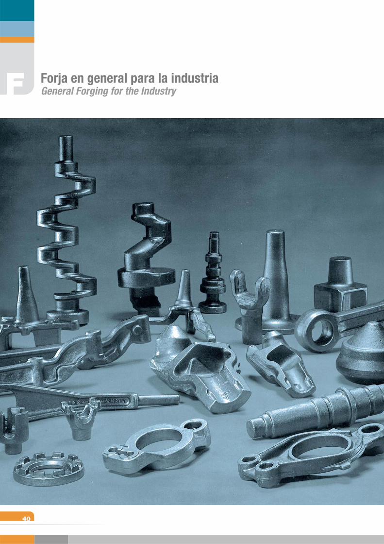
40
Forja en general para la industriaGeneral Forging for the IndustryF
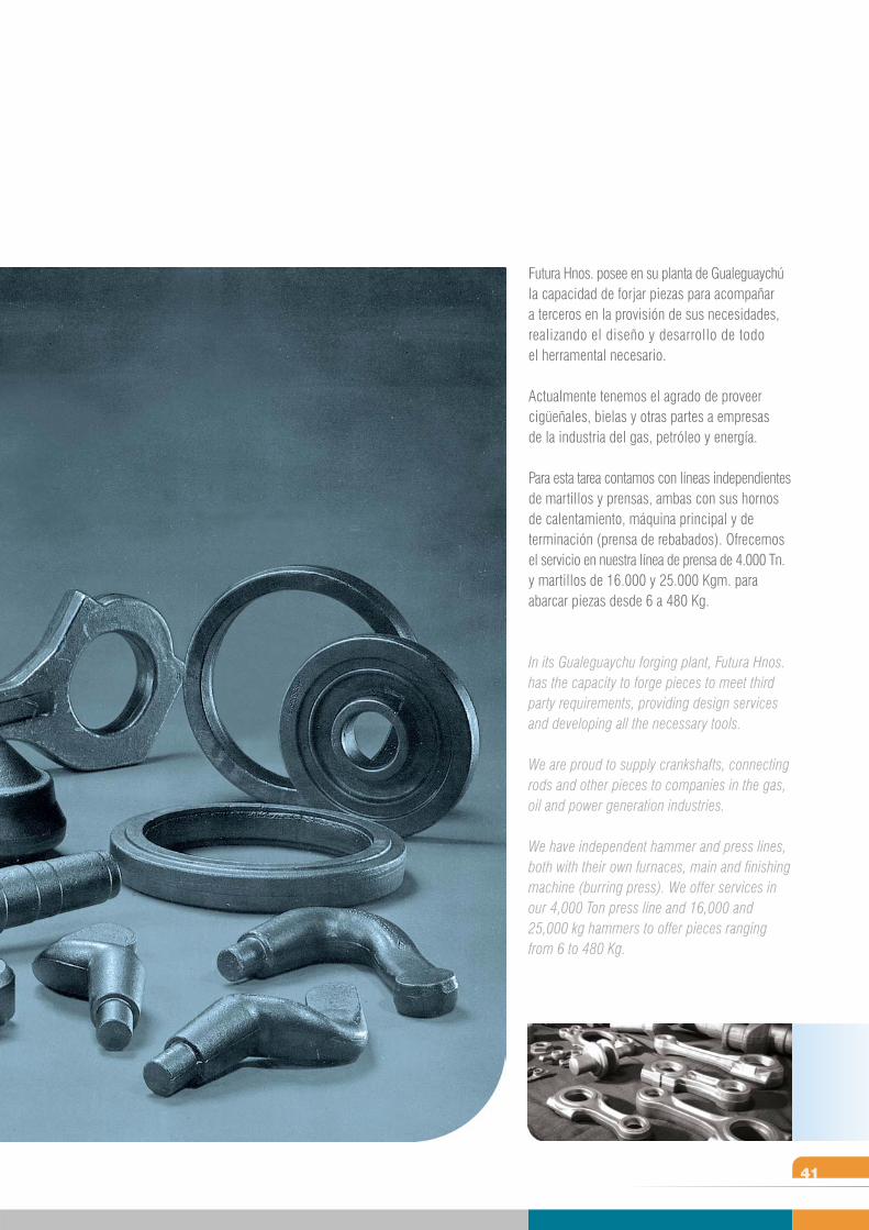
41
Futura Hnos. posee en su planta de Gualeguaychú la capacidad de forjar piezas para acompañar a terceros en la provisión de sus necesidades, realizando el diseño y desarrollo de todo el herramental necesario.
Actualmente tenemos el agrado de proveer cigüeñales, bielas y otras partes a empresas de la industria del gas, petróleo y energía.
Para esta tarea contamos con líneas independientes de martillos y prensas, ambas con sus hornos de calentamiento, máquina principal y de terminación (prensa de rebabados). Ofrecemos el servicio en nuestra línea de prensa de 4.000 Tn. y martillos de 16.000 y 25.000 Kgm. para abarcar piezas desde 6 a 480 Kg.
In its Gualeguaychu forging plant, Futura Hnos. has the capacity to forge pieces to meet third party requirements, providing design services and developing all the necessary tools.
We are proud to supply crankshafts, connecting rods and other pieces to companies in the gas, oil and power generation industries.
We have independent hammer and press lines, both with their own furnaces, main and finishing machine (burring press). We offer services in our 4,000 Ton press line and 16,000 and 25,000 kg hammers to offer pieces ranging from 6 to 480 Kg.
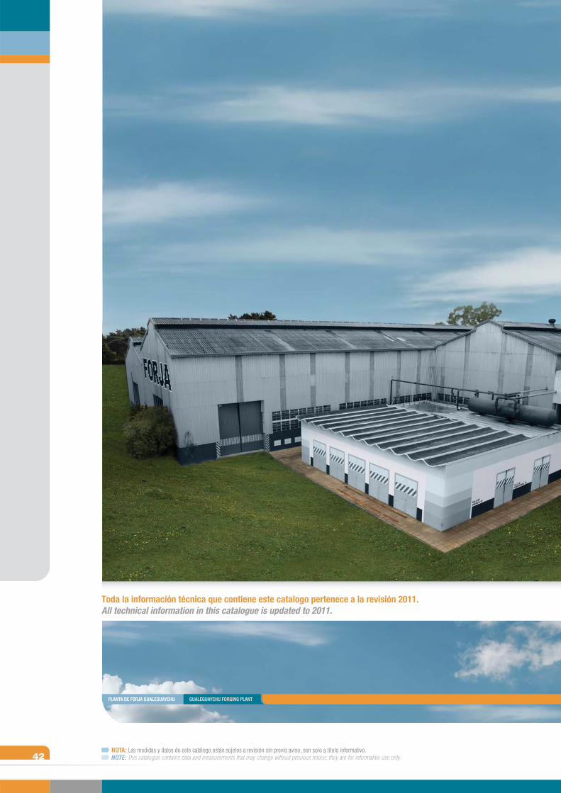
42NOTA: Las medidas y datos de este catálogo están sujetos a revisión sin previo aviso, son solo a título informativo.NOTE: This catalogue contains data and measurements that may change without previous notice; they are for informative use only.
Toda la información técnica que contiene este catalogo pertenece a la revisión 2011.All technical information in this catalogue is updated to 2011.
PLANTA DE FORJA GUALEGUAYCHU GUALEGUAYCHU FORGING PLANT

CATALOGO 2011CATALOGUE 2011
Lacarra 1256Ciudad autónoma de Bs. As. (C1407JQZ)Bs As - ArgentinaTel.: (54-11) 4671-0300Fax: (54-11) 4674-0431
ADMINISTRACION Y VENTASSALES AND ADMINISTRATION
Parque Industrial GualeguaychúEntre Ríos - Argentina
PLANTAPLANT
MARTILLO UTA 25.000 KGM 25,000 KG UTA HAMMER LINE
dg:w
ww.o
ryan
a.com
.ar