1.1. Motores de combustión interna
Un gran porcentaje de los motores de combustión interna, funcionan con el principio de
funcionamiento del pistón reciprocante (ver Figura 1) donde un pistón se desliza dentro
de un cilindro, desde el PMI( punto muerto infeior) y el PMS( punto muerto superior) y
viceversa, que a través de un mecanismo llamado biela-manivela transforma el
movimiento alternativo lineal en movimiento de rotación del cigüeñal transmitiendo
fuerza motriz.
Figura1 - Principio de funcionamiento de un MECH (Dante, 1964).
Beau Rochas en 1862 planteó el ciclo de funcionamiento para un motor mediante el
principio pistón-reciprocante, que en la actualidad es muy empleada en la fabricación de
motores encendidos por chispa. A continuación, se explica el ciclo o secuencia de
funcionamiento:
I. Admisión: una mezcla homogénea de aire-combustible ingresa al interior del
cilindro; donde el pistón pasa del PMS para el PMI. En el primer tiempo de la
Figura 2, se observa la válvula de admisión abierta.
II. Compresión: el pistón ya se encuentra en el PMI, donde el pistón comprime
la mezcla de aire-combustible, elevando la temperatura de la misma. En el
segundo tiempo de la Figura 1, se observa que ambas válvulas están
cerradas.
III. Expansión: cerca del final de la carrera de compresión, se produce la chispa
y encendido de la mezcla de aire-combustible, liberando energía que
aumenta la temperatura y la presión de los gases; inmediatamente desciende
el pistón transmitiendo la energía al cigüeñal. En el tercer tiempo de la Figura
1, se observa que ambas válvulas están cerradas
1

IV. Escape: se produce la expulsión de los gases producto de la combustión a
través del tubo de escape del vehículo. En el cuarto tiempo de la Figura 1 se
observa que la válvula de combustión abierta (Rochas, 1862).
El ciclo de Otto es un ciclo termodinámico utilizado como una base de comparación para
motores encendidos por chispa de cuatro tiempos. El ciclo consiste en cuatro etapas
como se muestra en la Figura 2.
.
Figura 2 - Etapas del ciclo Otto [32].
Para el ciclo Otto, se tiene las siguientes consideraciones: las etapas de expansión y
compresión son asumidos como procesos adiabáticos (no presenta transferencia de
calor) y son reversibles (isotrópicos). Las etapas son las siguientes:
1>2: compresión isotrópica del aire
2>3: aporte de calor Q23 a volumen constante.
3>4: expansión isotrópica de aire hacia el volumen original.
4>1: cesión de calor Q41 a volumen constante para completar el ciclo.
1.2. Gases fundamentales
La relación aire-combustible ideal para la combustión perfecta en un motor de gasolina
es 14,66:1. Esto se conoce como una relación aire-combustible estequiométrica. El
factor lambda (𝝀) es la relación aire combustible real entre la relación de aire-
combustible ideal (14,66). Este parámetro es más fácil de usar por las siguientes
razones:
𝝀 = 1 → mezcla de aire − combustible ideal
𝝀 < 1 → mezcla de aire − combustible rica
𝝀 > 1 → mezcla de aire − combustible pobre
2

Cuando una mezcla de combustible es pobre, se tiene demasiado aire y poco
combustible en la relación aire-combustible. Si una mezcla es rica, se tiene demasiado
combustible y poco aire en la mezcla. Los motores de combustión interna no poseen
100 % de eficiencia, incluso con mezclas de combustible ideal; por ello, otros
subproductos se forman durante la combustión y son expulsadas por el tubo de escape.
Los principales subproductos o gases emitidos por el motor de combustión interna
encendido por chispa son los siguientes:
Oxígeno residual (O2);
monóxido de carbono (CO);
dióxido de carbono (CO2);
los óxidos de nitrógeno (NOX);
hidrocarburos no quemados (HC).
En la Figura 3, se observa el nivel de las emisiones en relación con el factor lambda,
más adelante en este capítulo se explicará con mayor detalle el nivel de cada emisión.
Figura 3 - Concentraciones de emisiones vs el factor lambda (Someso, 2015).
De las emisiones mencionadas, las que generan mayores problemas en la salud y en
el ambiente son el monóxido de carbono, óxidos de nitrógenos y los hidrocarburos no
quemados. En el Perú, las inspecciones vehiculares verifican estos contaminantes
emitidos por un vehículo mayor a tres años de antigüedad. Las pruebas son realizadas
estando el vehículo parado y el motor en vacío.
3

1.2.1. Oxigeno (O2)
En la atmosfera, se tiene un porcentaje, aproximadamente, de 21 % de O2. Por ello, el
nivel de oxígeno en el gas de escape es un indicador de la relación de la mezcla de aire-
combustible. El O2 se origina en el aire inyectado al motor y se mezcla con los HC para
la combustión.
Figura 4 - Concentración de Oxigeno vs Lambda (Infrared, 2015).
En la Figura 4, se puede observar cuando la mezcla de combustible es rica, la
concentración de O2 residual se encuentra en un nivel bajo y constante. Esto quiere decir
que hay un menor residuo de O2 ya que todo el oxígeno se consume en el proceso de
combustión. En cambio, a medida que la mezcla se pone más pobre, la concentración
de O2 aumenta de manera constante, ya que menos de la misma se utiliza en el proceso
de combustión. Por ello, las mayores concentraciones de O2 en los gases de escape
son directamente proporcionales a las mezclas pobres de aire-combustible. El O2 es
una emisión producto de la combustión pero no es un contaminante para las personas
y medio ambiente.
1.2.2. Hidrocarburos no quemados (HC)
Los hidrocarburos no quemados son compuestos orgánicos conformados por átomos
de hidrógeno y carbono. El HC presente en los gases de escape del motor de
combustión interna de encendido por chispa es la gasolina parcialmente quemada o sin
quemar, y se mide en partes por millón (ppm). Los niveles de HC varían respecto a la
relación de aire-combustible.
4
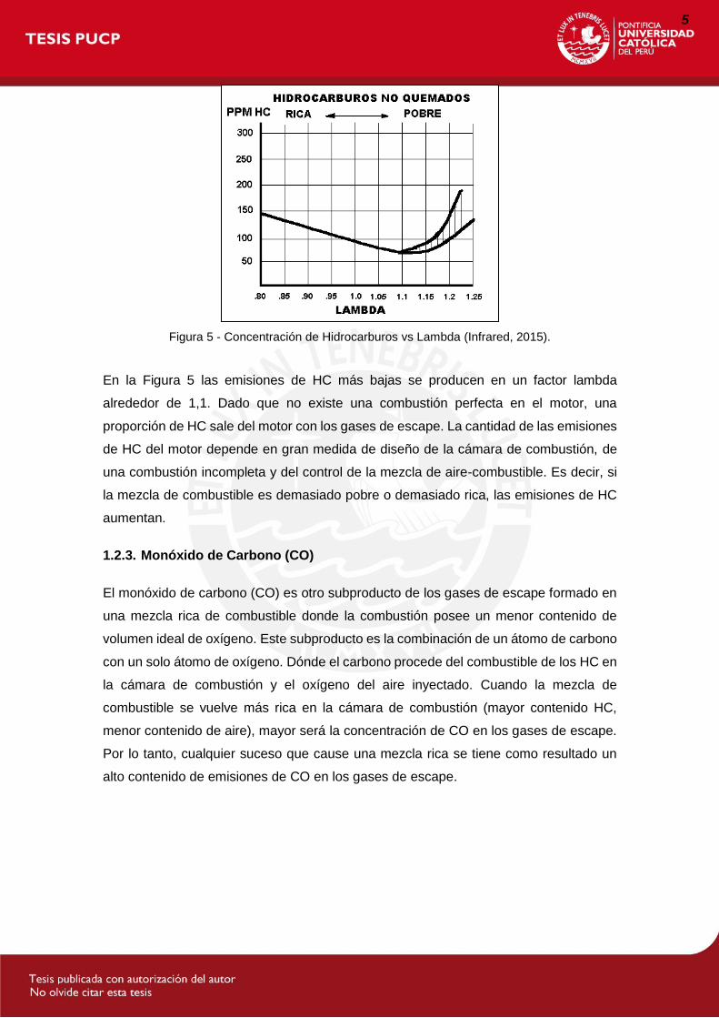
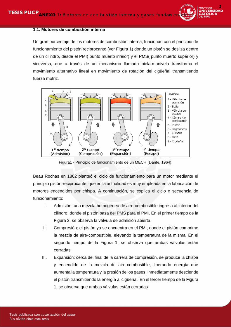
Figura 5 - Concentración de Hidrocarburos vs Lambda (Infrared, 2015).
En la Figura 5 las emisiones de HC más bajas se producen en un factor lambda
alrededor de 1,1. Dado que no existe una combustión perfecta en el motor, una
proporción de HC sale del motor con los gases de escape. La cantidad de las emisiones
de HC del motor depende en gran medida de diseño de la cámara de combustión, de
una combustión incompleta y del control de la mezcla de aire-combustible. Es decir, si
la mezcla de combustible es demasiado pobre o demasiado rica, las emisiones de HC
aumentan.
1.2.3. Monóxido de Carbono (CO)
El monóxido de carbono (CO) es otro subproducto de los gases de escape formado en
una mezcla rica de combustible donde la combustión posee un menor contenido de
volumen ideal de oxígeno. Este subproducto es la combinación de un átomo de carbono
con un solo átomo de oxígeno. Dónde el carbono procede del combustible de los HC en
la cámara de combustión y el oxígeno del aire inyectado. Cuando la mezcla de
combustible se vuelve más rica en la cámara de combustión (mayor contenido HC,
menor contenido de aire), mayor será la concentración de CO en los gases de escape.
Por lo tanto, cualquier suceso que cause una mezcla rica se tiene como resultado un
alto contenido de emisiones de CO en los gases de escape.
5

Figura 6 - Concentración de Monóxido de Carbono vs Lambda (Infrared, 2015).
La Figura 6 muestra que el nivel de CO disminuye a medida que el factor lambda se
acerca aproximadamente 1,05, y mantiene este nivel bajo incluso mientras la mezcla se
vuelve más pobre. En consecuencia, CO es un buen indicador para saber si la mezcla
de combustible es rica o pobre. Por ello, este factor hace que los contenidos de las
emisiones de HC y CO en los gases de escape son buenos indicadores del rendimiento
del motor, además de su importancia para el cumplimiento de las normas
internacionales de aire limpio. Cuando las lecturas de HC y CO se comparan con las
lecturas de oxígeno y de dióxido de carbono, los resultados pueden ser utilizados para
indicar la capacidad catalítica del convertidor.
1.2.4. Dióxido de Carbono (CO2)
El dióxido de carbono es un subproducto de la combustión formado con un átomo de
carbono enlaza con dos átomos de oxígeno (una molécula de oxígeno), y por la
oxidación de CO en el convertidor catalítico. A diferencia de CO, CO2 es relativamente
inofensiva; ya que animales emiten CO2 como un subproducto de la respiración.
6
Figura 7 - Concentración de Dióxido de Oxigeno vs Lambda (Infrared, 2015).
El CO2 es un buen indicador de la eficiencia de la combustión debido a su volumen en
los puntos más altos de concentración de los gases escape en proporciones de aire-
combustible estequiométrica. En la Figura 7, se observa las altas concentraciones de
CO2 se da cuando el factor lambda igual a uno y disminuye cuando la mezcla se vuelve
más pobre o más rico. Esto se puede tomar que el CO2 como un buen indicador para
conocer si la combustión fue eficiente. Además, las concentraciones de CO2 también se
pueden utilizar como un indicador de la integridad del sistema de escape.
1.2.5. Óxidos de Nitrógeno (NOx)
El nitrógeno constituye aproximadamente el 78 % del aire en la atmósfera de la Tierra,
y el oxígeno alrededor del 21 %. Por lo tanto, sobre 78 % del aire en la cámara de
combustión es nitrógeno. Este elemento es inerte y no contribuye a, o resta, al proceso
de combustión. El nitrógeno y el oxígeno sólo se combinan entre sí para formar óxidos
nocivos para la salud y el ambiente, incluidos óxido nítrico (NO) y dióxido de nitrógeno
(NO2), cuando ambos elementos gaseosos se calientan por encima de 2500°F (1371 °
C). Los NOx incluyen todos los compuestos de nitrógeno formados en la cámara de
combustión de un motor, incluyendo el óxido nítrico (NO) y dióxido de nitrógeno (NO2).
Por ello, el subíndice x en lugar de números indica que todos los compuestos de
nitrógeno/oxígeno se incluyen.
Debido a algunas condiciones del motor de combustión interna encendido por chispa,
las temperaturas de la cámara de combustión superan fácilmente los 1371ºC y se origina
la combinación de oxígeno y nitrógeno para formar NOx.
7

Figura 8 - Concentración de Óxido de Nitrógeno vs Lambda (Infrared, 2015).
La Figura 8 muestra la concentración de NOx en relación con el factor lambda. Las altas
temperaturas de la cámara de combustión se da cuando lambda esta alrededor de 1,1,
lo que permite la formación de alta concentración de NOx.
NOx no indica el rendimiento del motor o la eficiencia, en cambio, el oxígeno,
hidrocarburos, monóxido de carbono y dióxido de carbono si son indicadores de
eficiencia. La formación de NOx no afecta al rendimiento del motor, pero algunos
dispositivos utilizan este factor para evitar la formación que pueden afectar al
rendimiento y contribuir a los niveles más altos de HC y CO.
8

9

EAGLE files: arduino-mega2560-reference-design.zip Schematic: arduino-mega2560-schematic.pdf
Microcontroller ATmega2560Operating Voltage 5VInput Voltage (recommended) 7-12VInput Voltage (limits) 6-20VDigital I/O Pins 54 (of which 14 provide PWM output)Analog Input Pins 16DC Current per I/O Pin 40 mADC Current for 3.3V Pin 50 mAFlash Memory 256 KB of which 8 KB used by bootloaderSRAM 8 KBEEPROM 4 KBClock Speed 16 MHz
10

56 Air-mass meters A B
Hot-film air-mass meter, Type HFM 5Measurement of air-mass throughflow up to 1000 kg/h
Technical data / range
Nominal supply voltage UN 14 VSupply-voltage range UV 8...17 VOutput voltage UA 0...5 VInput current IV < 0.1 APermissible vibration acceleration ≤ 150 ms–2
Time constant τ63 1) ≤ 15 msTime constant τ∆ 2) ≤ 30 msTemperature range –40...+120 °C 3)
Part number 0 280 217 123 0 280 218 019 0 280 217 531 0 280 218 008 0 281 002 421Measuring range Qm 8...370 kg/h 10...480 kg/h 12...640 kg/h 12...850 kg/h 15...1000 kg/hAccuracy 4) ≤ 3% ≤ 3% ≤ 3% ≤ 3% ≤ 3%Fitting length LE 22 mm 22 mm 22 mm 16 mm 22 mmFitting length LA 20 mm 20 mm 20 mm 16 mm 20 mmInstallation length L 96 mm 96 mm 130 mm 100 mm 130 mm Connection diam. D 60 mm 70 mm 80 mm 86/84 mm 6) 92 mmVenturi ID 50 mm 62 mm 71 mm 78 mm 82 mmPressure drop at nominal air mass 5) < 20 hPa < 15 hPa < 15 hPa < 15 hPa < 15 hPaTemperature sensor Yes Yes Yes No YesVersion 1 2 3 4 51) In case of sudden increase of the air-mass flow from 10 kg · h–1 auf 0,7 Qm nominal, time required to reach
63% of the final value of the air-mass signal.2) Period of time in case of a throughflow jump of the air mass | ∆ m/m | ≤ 5%.3) For a short period up to +130 °C.4) |∆Qm/Qm|: The measurement deviation ∆Qm from the exact value, referred to the measured value Qm.5) Measured between input and output6) Inflow/outflow end
Accessories for connector
Plug housing Contact pins Individual gaskets For conductor cross-section1 928 403 836 1 987 280 103 1 987 280 106 0.5...1 mm2
1 987 280 105 1 987 280 107 1.5...2.5 mm2
Note: Each 5-pole plug requires 1 plug housing, 5 contact pins, and 5 individual gaskets.For automotive applications, original AMP crimping tools must be used.
ApplicationIn order to comply with the vehicleemission limits demanded by law, it isnecessary to maintain a given air/fuel ratioexactly. This requires sensors which preciselyregister the actual air-mass flow and outputa corresponding electrical signal to theopen and closed-loop control electronics.
DesignThe micromechanical sensor element islocated in the plug-in sensor’s flow pas-sage. This plug-in sensor is suitable forincorporating in the air filter or, using ameasurement venturi, in the air-intake pas-sages. There are different sizes of mea-surement venturi available depending uponthe air throughflow. The micromechanicalmeasuring system uses a hybrid circuit,and by evaluating the measuring data isable to detect when return flow takes placeduring air-flow pulsation.
Operating principleThe heated sensor element in the air-massmeter dissipates heat to the incoming air.The higher the air flow, the more heat isdissipated. The resulting temperature differ-ential is a measure for the air mass flowingpast the sensor. An electronic hybrid circuit evaluates thismeasuring data so that the air-flow quantitycan be measured precisely, and its direc-tion of flow.Only part of the air-mass flow is registeredby the sensor element. The total air massflowing through the measuring tube isdetermined by means of calibration, knownas the characteristic-curve definition.
Qm U
P Compact design.P Low weight.P Rapid response.P Low power input.P Return-flow detection.
ApplicationIn internal-combustion engines, this sensoris used for measuring the air-mass flow so that the injected fuel quantity can beadapted to the presently required power, tothe air pressure, and to the air temperature.
Explanation of symbolsQm Air-mass flow rate∆Qm Absolute accuracy ∆Qm/Qm Relative accuracyτ∆ Time until measuring error is
≤ 5%τ63 Time until measured-value change
63%
22223_1021En_056-057 12.07.2001 10:07 Uhr Seite 56
11
B A
Air-mass meters 57
1
2
3
4
5
ϑu
ϑ ϑ
ϑ
ϑ
UK
RH
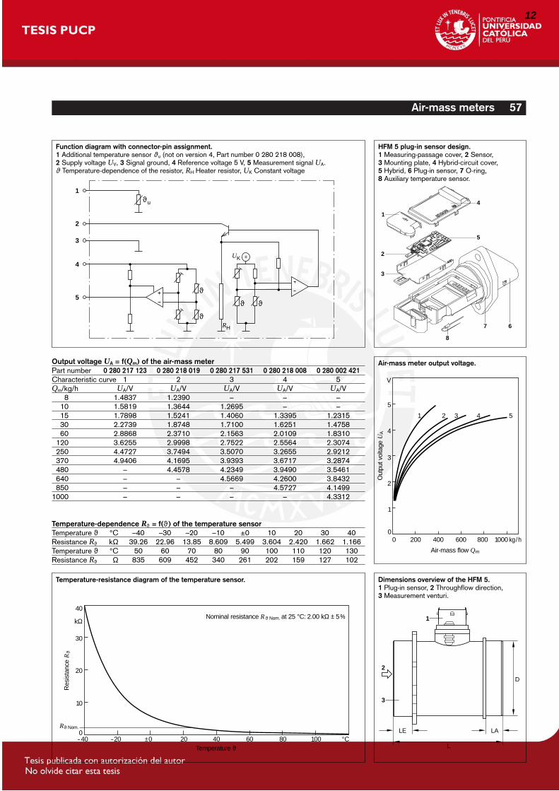
Function diagram with connector-pin assignment.1 Additional temperature sensor ϑu (not on version 4, Part number 0 280 218 008), 2 Supply voltage UV, 3 Signal ground, 4 Reference voltage 5 V, 5 Measurement signal UA.ϑ Temperature-dependence of the resistor, RH Heater resistor, UK Constant voltage
1
4
5
2
3
8
7 6
HFM 5 plug-in sensor design.1 Measuring-passage cover, 2 Sensor, 3 Mounting plate, 4 Hybrid-circuit cover, 5 Hybrid, 6 Plug-in sensor, 7 O-ring, 8 Auxiliary temperature sensor.
00
1
2
3
4
5
V
200 400
Air-mass flow Qm
600 800 1000 kg/h
2 3 4 51
Out
put v
olta
ge U
A
Air-mass meter output voltage.
2
3
L
D
LE
1
LA
Dimensions overview of the HFM 5.1 Plug-in sensor, 2 Throughflow direction, 3 Measurement venturi.
-400
10
20
30
40
kΩ
-20 ±0 20 40 60 80 100 °CTemperature ϑ
Res
ista
nce
Rϑ
Rϑ Nom.
Nominal resistance R ϑ Nom. at 25 °C: 2.00 kΩ ± 5 %
Output voltage UA = f(Qm) of the air-mass meterPart number 0 280 217 123 0 280 218 019 0 280 217 531 0 280 218 008 0 280 002 421Characteristic curve 1 2 3 4 5Qm/kg/h UA/V UA/V UA/V UA/V UA/V1118 1.4837 1.2390 – – –1110 1.5819 1.3644 1.2695 – –1115 1.7898 1.5241 1.4060 1.3395 1.23151130 2.2739 1.8748 1.7100 1.6251 1.47581160 2.8868 2.3710 2.1563 2.0109 1.83101120 3.6255 2.9998 2.7522 2.5564 2.30741250 4.4727 3.7494 3.5070 3.2655 2.92121370 4.9406 4.1695 3.9393 3.6717 3.28741480 – 4.4578 4.2349 3.9490 3.54611640 – – 4.5669 4.2600 3.84321850 – – – 4.5727 4.14991000 – – – – 4.3312
Temperature-dependence Rϑ = f(ϑ) of the temperature sensor Temperature ϑ °C –40 –30 –20 –10 ±0 10 20 30 40Resistance Rϑ kΩ 39.26 22.96 13.85 8.609 5.499 3.604 2.420 1.662 1.166Temperature ϑ °C 50 60 70 80 90 100 110 120 130Resistance Rϑ Ω 835 609 452 340 261 202 159 127 102
Temperature-resistance diagram of the temperature sensor.
22223_1021En_056-057 12.07.2001 10:07 Uhr Seite 57
12

FGA4500GAS ANALYZER
When you need a reliable gas analyzer that can accurately speed
up your emissions, tune-ups, and diagnostics testing, the Infrared
Industries FGA4500 is the perfect answer. By offering immediate
results, the FGA4500 Gas Analyzer is the fastest machine on the
market. Certifi ed to BAR and OIML standards, this gas analyzer
provides a portable, accurate, and quick solution for every tune-up
and automotive mechanic shop.
The FGA4500 measures fi ve gases including Hydrocarbons (HC),
Carbon Monoxide (CO), Carbon Dioxide (CO2), Oxygen (O2), and
Oxides of Nitrogen (NOX). Simple to operate and simple to maintain
in the fi eld, this unit lasts for many years. Economical fi lters and
sensors are replaced in seconds, and the sample cell and optics can
easily be cleaned in the fi eld!
The FGA4500 will instantaneously calculate Air to Fuel Ratio
(AFR), Lambda (λ), and Grams per Mile (GPM) or Grams
per Kilometer (GPK) in real time. When attached to a tachometer,
it reads engine speeds to 30,000 RPM. The optional built-
in printer documents test results and allows shop owners to
print their shop name, address, and other custom header
text on the printout for customers’ records. You can diagnose
fuel-related issues accurately and quickly to provide the service
that your customers need.
For those seeking performance tuning, analog outputs allow the
connection to a dynamometer, chart recorder or data acquisition
console to conveniently display all essential information from the
analyzer.
The FGA4500 measures exhaust gases from two tail pipes and gives
you the average reading, or can set up an exhaust dilution. This
feature will not only warn you when there is a leak in your exhaust
system, it will also alert you when the exhaust probe is not fully
inserted in the tailpipe.
Take the FGA4500 on the road with optional battery or by
connecting the unit to the cigarette lighter via the 12-volt jack
and see how the vehicle behaves in real driving situations.
Or, plug it into a standard 100-240 VAC outlet for extended in-
shop use. You can use the internal record feature to store all
measurements and then download the information to a PC when
you return. Instead of spending hundreds or thousands of dollars for
a dynamometer or test cell, you can now achieve real-world results
right from the driver’s seat of the car.
The FGA4500 is a cost-effective, all-in-one performer, which
makes it the perfect trouble-shooting tool for your diagnostic
needs. Automotive, motorcycle, or any exhaust emissions are ideal
applications where detection of up to 5 different gases is required.
© 2012 Infrared Industries, Inc. All Rights Reserved. Contents and specifications are subject to change.
FGA4500 Features:• Quick 2 second response time
• Multi-language LCD Display
• Measures up to 5 gases: HC, CO, CO2, O2 and NOX
• Displays RPM, AFR, and Lambda
• Built-In data recorder
• Internal/External Printer ALL-IN-ONE FAST PERFORMING DIAGNOSTIC TOOL
Infrared Industries was the fi rst company to develop a gas analyzer
for automotive use. This patented revolutionary analyzer was used
exclusively by Sun, Bear, Allen Test, and other companies throughout
the 1970s and 1980s. With over 40 years of experience in developing
and manufacturing gas analyzers for the automotive, industrial,
petroleum, utilities, analytic, and environmental industries, you can
be assured that Infrared Industries has the knowledge and the know-
how to produce the fi nest automotive analyzer available today.
COMPANY OVERVIEW
Toll Free | 800.344.0321
Tel | 510.782.8100
Fax | 510.782.8101
www.InfraredIndustries.com
13
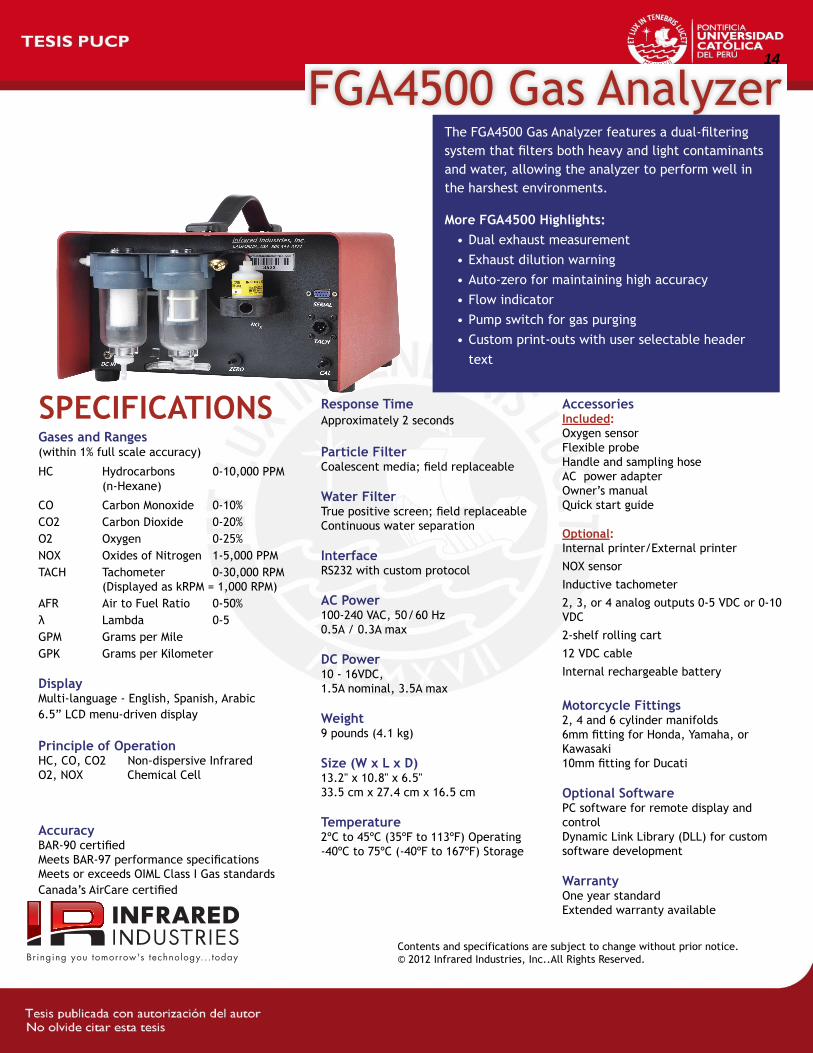
FGA4500 Gas AnalyzerThe FGA4500 Gas Analyzer features a dual-fi ltering
system that fi lters both heavy and light contaminants
and water, allowing the analyzer to perform well in
the harshest environments.
More FGA4500 Highlights:
• Dual exhaust measurement
• Exhaust dilution warning
• Auto-zero for maintaining high accuracy
• Flow indicator
• Pump switch for gas purging
• Custom print-outs with user selectable header
text
Contents and specifications are subject to change without prior notice.
© 2012 Infrared Industries, Inc..All Rights Reserved.
Gases and Ranges (within 1% full scale accuracy)
HC Hydrocarbons 0-10,000 PPM
(n-Hexane)
CO Carbon Monoxide 0-10%
CO2 Carbon Dioxide 0-20%
O2 Oxygen 0-25%
NOX Oxides of Nitrogen 1-5,000 PPM
TACH Tachometer 0-30,000 RPM
(Displayed as kRPM = 1,000 RPM)
AFR Air to Fuel Ratio 0-50%
λ Lambda 0-5
GPM Grams per Mile
GPK Grams per Kilometer
DisplayMulti-language - English, Spanish, Arabic
6.5” LCD menu-driven display
Principle of OperationHC, CO, CO2 Non-dispersive Infrared
O2, NOX Chemical Cell
AccuracyBAR-90 certifi ed
Meets BAR-97 performance specifi cations
Meets or exceeds OIML Class I Gas standards
Canada’s AirCare certifi ed
Response TimeApproximately 2 seconds
Particle FilterCoalescent media; fi eld replaceable
Water FilterTrue positive screen; fi eld replaceable
Continuous water separation
InterfaceRS232 with custom protocol
AC Power100-240 VAC, 50/60 Hz
0.5A / 0.3A max
DC Power10 - 16VDC,
1.5A nominal, 3.5A max
Weight9 pounds (4.1 kg)
Size (W x L x D)13.2" x 10.8" x 6.5"
33.5 cm x 27.4 cm x 16.5 cm
Temperature2ºC to 45ºC (35ºF to 113ºF) Operating
-40ºC to 75ºC (-40ºF to 167ºF) Storage
AccessoriesIncluded:Oxygen sensor
Flexible probe
Handle and sampling hose
AC power adapter
Owner’s manual
Quick start guide
Optional:Internal printer/External printer
NOX sensor
Inductive tachometer
2, 3, or 4 analog outputs 0-5 VDC or 0-10
VDC
2-shelf rolling cart
12 VDC cable
Internal rechargeable battery
Motorcycle Fittings 2, 4 and 6 cylinder manifolds
6mm fi tting for Honda, Yamaha, or
Kawasaki
10mm fi tting for Ducati
Optional SoftwarePC software for remote display and
control
Dynamic Link Library (DLL) for custom
software development
WarrantyOne year standard
Extended warranty available
SPECIFICATIONS
14

Hu-32
Hu
1.0 m(3.0')
CABLE
4-PINCONNECTOR
19 (0.75'') dia.25.4 to 227(1 to 9)VARIABLEDEPTHFLANGE
REMOVABLESTAINLESS STEEL
FILTER CAP
254 (10.0)
Comes with mating connector, removable protective sensor filter, removable duct flange,wall mounting bracket, and operator’s manual.Ordering Example: HX94C, duct mount RH/temperature transmitter with 4 to 20 mA output, £178.
To Order (Specify Model Number)Model No. Price DescriptionHX94C £178 RH/temp transmitter with 4 to 20 mA outputs with 4 pin connectorHX94V 178 RH/temp transmitter with 0 to 1 Vdc outputs with 4 pin connectorHX94CW 157 RH/temp transmitter with 4 to 20 mA outputs with 1 m (3') lead wiresHX94VW 157 RH/temp transmitter with 0 to 1 Vdc outputs with 1 m (3') lead wiresHX94CNPT 164 RH/temp transmitter with 4 to 20 mA outputs with 1⁄2" male
NPT fitting and 1 m (3') leadsHX94VNPT 164 RH/temp transmitter with 0 to 1 Vdc outputs with 1⁄2" male
NPT fitting and 1 m (3') leadsHX94-MC Spare 4 pin mating connectorPSR-24S 40 Regulated power supply, US plug, 90 to 264 Vac input, 24 Vdc output,
400 mA, screw terminals, ULPSR-24L 40 Regulated power supply, US plug, 90 to 264 Vac input, 24 Vdc output,
400 mA, stripped leads, ULPSR-24L-230 40 Regulated power supply, European plug, 230 Vac input, 24 Vdc output,
400 mA, stripped leads, CEPSU-93 27 Unregulated power supply, 16 to 23 Vdc, 300 mA max, screw terminalTX4-100 4 conductor shielded transmitter cable, 30 m (100') CAL-3-HU NIST-traceable calibration
4
3 2
1
+
*R2
*R1
PROBECONNECTOR
*R1 and R2 CAN COMBINE IN ONE WIRE PLUS JUMPER PINS 1 AND 2
TEMP.METERORRECORDER
RH METER ORRECORDER
6-30 VDCPOWERSUPPLY
R L
OA
DR
LO
AD
MAX R LINES = (V SUPPLY-6)/0.02For 1 to 5 Volt Output, R Load = 250 Ohm
-
+
-+
-
4
3 2
1
+PROBE
CONNECTOR
TEMP.METERORRECORDER
RH METER ORRECORDER
6-30 VdcPOWERSUPPLY-
+
-+
-
HX94C Current Hook-Up
HX94V Voltage Hook-Up
MECHANICALHousing: Stainless steel NEMA-4 enclosureProbe: 254 x 19 mm (10 x 0.75") dia.,305 mm (12") cableDuct Flange: Removable, variable 25.4 to 227 mm (1 to 9") depth. 70 mm(2.75") dia., duct hole 21 mm (0.812") dia.4 mtg holes. 4 mm (0.156") dia. (for #6sheet metal screws) on 51 mm (2.00") dia.circle. Wall mounting bracket included.Connections: HX94C/94V: 4 pin matingconnector accepts 26 to 18 AWG wires.HX94CW/94VW: 1 m (3') braided andshielded cable, PVC sheathing.HX94CNPT/94VNPT: 1⁄2" male NPT conductor with 1 m (3')braided/shielded cableWeight: 198 g (7 oz) with duct flange
HX94 SeriesStarts at
£157
SpecificationsRELATIVE HUMIDITYThin-Film Polymer CapacitorInput Voltage Range: 6 to 30 Vdc, (polarity protected)Range/Accuracy/Repeatability:3 to 95% RH/±2% RH/±1% RHTemperature Compensation:-20 to 85°C (4 to 185°F)Current Output:HX94C: 4 to 20 mA (0 to 100% RH)Voltage Output:HX94V: 0 to 1.0 Volt (0 to 100% RH)Time Constant: (for 90% response at25°C; in moving air, 1m/sec.)
Less than 20 seconds, 10 to 90% RHLess than 30 seconds, 90 to 10% RHTEMPERATUREThin-Film 100 ohm Platinum RTD (DIN 43760)Input Voltage Range:6 to 30 Vdc, (Polarity Protected)Range: 0 to 100°C (32 to 212°F)Accuracy: ±0.6°C (±1°F)Repeatability: ±0.3°C (±0.5°F)Current Output:HX94C: 4 to 20 mA for 0 to 100°CVoltage Output: HX94V: 0 to 1.0 Volt for 0 to 100°CTime Constant: (for 60% response)Less than 2 seconds in moving air(1m/sec) Less than 10 seconds in still air
Stainless SteelNEMA-4 Housing3 Different OutputConnection StylesAvailable forMounting Versatility4 to 20 mA/0 to 1 Vdc OutputsRemovable Stainless SteelSensor Filter for Cleaning Ease
Relative HumidityTemperature Transmitters
The HX94 relative humidity/temperature transmitter provides a reliable and low cost method for duct mount monitoring applications. Solid statesensors provide excellent sensitivity, fast response, and stability.Simple hookup and linearisedoutput permit interfacing with mostdisplay and control devices.
ALL MODELS AVAILABLE FOR FAST DELIVERY!
Dimensions mm (inches)
6.70
1984
15
16

17
Recommended