DESCRIPCIÓN DEL PANEL
Specifications subject to change without notice.
INFORMACION PARA ORDENAR
EL-3000GD1BH
ACCESRIOS OPCIONALES
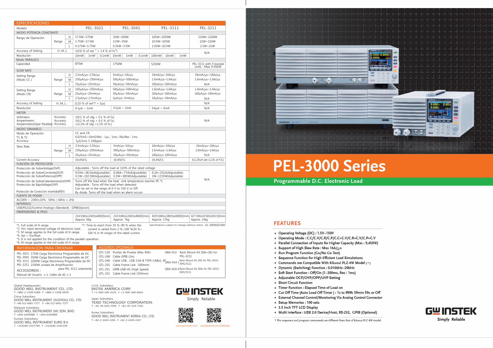
COMBINACIONES FLEXIBLES DE POTENCIA, ALTA VELOCIDAD Y
VERSATILIDAD EN SIMULADORES DE CARGA
La serie PEL-3000 es una carga electrónica programable, de DC de un canal con resolución de 0.01mA y una corriente de 16A/μ s,
ideal para probar fuentes de alimentación de servidores y SPS (Fuentes de Switcheo) de computadoras Industriales y Comerciales. Para Servidores
como los cloud ecosystem corriendo operaciones las 24-hour, se requiere de una fuente de poder de alta potencia, con rango desde 350W a 1500W, is
para mantener la operación normal, tanto del Hub, como del equipo de almacenamiento comunicaciones de internet. Debido a la
demanda creciente de transmision de datos y al almacenamiento en gran escala de los sistemas de telecomunicación, y la infraestructura del internet
se encuentran en rápida expansión. Esto a incrementado la demanda en el mercado de fuentes para equipo de telecomunicaciones
en el área de 2000W y mayores. La combinación flexible de potencia de la serie PEL-3000 cumple con estas
expectativas. Con respecto a aplicaciones de pruebas a baterias como baterias recargables para herramienta eléctrica, y
baterías para automóviles, la serie PEL-3000 tiene tres modelos, 175W, 350W, 1050W y 1050W. Conectando amplificadores
de 2100W a unidades maestras, la capacidad maxima de cargadel sistema puede llegar a 9450W. Por lo que, la serie PEL-3000 cumple
varios requerimeintos de prueba de potencia incluyendo potencia mediana a baja o fuentes de poder de alta potencia.
La serie PEL-3000 tiene siete modos de operación y tres funciones de operación. Entre los siete modos de operación, cuatro de ellas son modos
básicos, incluyendo corriente constante, voltaje constante, resistencia constante, y potencia constante, y las otros tres son modos avanzados
de operación incluyendo corriente constante + voltaje constante, resistencia constante + voltaje constante, y potencia constante + voltaje
constante. El usuario debe seleccionar primero el modo de operación y luego la función de operación basados en los requerimientos de prueba. Funciones de operación
Estaticas y Dinamicas se pueden aplicar a diferentes condiciones de prueba incluyendo un nivel fijo de carga, switchando entre dos niveles o
switchando entre mas de dos niveles. Las funciones de secuencia estan divididas en secuencias Rápidas y secuencias Normales de acuerdo al tiempo de prueba
de cada paso. Ambas funciones Dinamica y Secuenciada están para aisitir al usuario en la simulación de cambios reales en la carga. Por ejemplo, la PEL-3000 puede simular
consumo de corriente HEV para asegurar que la batería del automóvil pueda abastecer HEV con el suficiente poder. El llevar a cabo,
esta prueba, los manufactureros pueden elevar la calidad del producto y la confiabilidad.
La alta velocidad de cambio de 16A/μ s simula las velocidades de subida y bajada de diferentes corrientes de carga para probar el tiempo de respuesta
de la fuente de poder. La Función de Encendido Suave de la PEL-3000 puede programar el tiempo de subida de la corriente para el momento
que el PEL-3000 es encendido para reducir la situación abnormal de caída de voltaje de la fuente bajo prueba. La función ajustable de protección de bajo voltaje (UVP),
PASA/NO PASA, Las Funciónes de monitoreo de corriente y de Temporizador para controlar el tiempo de activación de la carga pueden
s e r a p l i c a do s e n c on j u n to pa r a l a d e s c a rg a d e l a ba t e r í a pa r a e v i t a r d añ a r l a . B a s ado s e n l a s f u n c i o n a l i d ade s
descritas anteriormente, la serie PEL-3000 puede probar una gran variedad de fuentes de poder que van desde corrientes estáticas fundamentales
hasta simulaciones complejas de carga para mejorar la calidad y confiabilidad del producto.
CARGA ELECTRÓNICA DE DC, SERIE PEL-3000
La serie PEL-3000 es una Carga de DC, de alta velocidad, un solo canal y programable .
DESCRIPCIÓN DE LA SERIE PEL-3000 :
MODEL PEL-3021 PEL-3041 PEL-3111 PEL-3211
Potencia
Funcion
Combinacion
Paralela
Tamaño
175W 350W 1,050W 2,100W Booster
Full-function Una unidad Full-function Una Unidad Full-function Una UnidadNo panel de control, no
opera sola
Paralela con mismo
modelo 5 unidades
max
Paralela con mismo
modelo 5 unidades
max
Paralela con mismo
modelo 5 unidades max
Paralelo con Max
4, PEL-3211s
Paraleo con PEL-3111
Half Rack Half Rack Full Rack Full Rack
ACCESSORIOS :Manual de Usuario x 1, Cable de AC x 1
175W Carga Electrónica Programable de DC
350W Carga Electrónica Programable de DC
1050W Carga Electrónica Programable de DC
2100W unidad de Amplificación
para PEL-3111 solamente
PEL-3021
PEL-3041
PEL-3111
PEL-3211
GTL-248 Cable GPIB (2m)
GTL-120 Puntas de Prueba (Max 40A)
GTL-255 Cable Frame Link (300mm)
GTL-246 Cable USB , USB 2.0A-B TYPE CABLE, 4P
GTL-251 GPIB-USB-HS (High Speed)
GTL-252 Cable Frame Link (550mm)
GRA-413
GRA-414-J
GRA-414-E
Rack Mount Kit (EIA+JIS) for
PEL-3211
Rack Mount Kit (JIS) for PEL-3021/ 3041/3111
Rack Mount Kit (EIA) for PEL-3021/ 3041/3111
*1. Full scale of H range.*2. Vin: input terminal voltage of electronic load.*3. M range applies to the full scale of H range.*4. Set = Vin/Rset.*5. It is not applied for the condition of the parallel operation.*6. M range applies to the full scale of H range.
*7. Time to reach from 10 %~90 % when the
current is varied from 2 %~100 %(20 %~
100 % in M range) of the rated current.
Modelo PEL-3021 PEL-3041 PEL-3111 PEL-3211
Accuracy of Setting
MODO POTENCIA CONSTANTE
Rango de Operación
SLEW RATE
Capacidad
Setting Range
(Modo CC )
Setting Range
(Modo CR)
Range
Range
Range
H ,M , L
H ,M , L
H
M
L
H
M
L
H
M
L
10mW 1mW 0.1mW 10mW 1mW 0.1mW 100mW 10mW 1mW
*5 *6±(0.6 % of set + 1.4 % of f.s )
17.5W~175W
1.75W~17.5W
0.175W~1.75W
35W~350W
3.5W~35W
0.35W~3.5W
105W~1050W 210W~2100W
10.5W~105W 21W~210W
1.05W~10.5W 2.1W~21W
2.5mA/ms~2.5A/ms
250mA/ms~250mA/ms
25mA/ms~25mA/ms
250mA/ms~250mA/ms
25mA/ms~25mA/ms
2.5mA/ms~2.5mA/ms
5mA/ms~5A/ms
500mA/ms~500mA/ms
50mA/ms~50mA/ms
500mA/ms~500mA/ms
50mA/ms~50mA/ms
5mA/ms~5mA/ms
16mA/ms~16A/ms 16mA/ms~16A/ms
1.6mA/ms~1.6A/ms 1.6mA/ms~1.6A/ms
160mA/ms~160mA/ms
1.6mA/ms~1.6A/ms 1.6mA/ms~1.6A/ms
160mA/ms~160mA/ms 160mA/ms~160mA/ms
16mA/ms~16mA/ms
Resolución
Modo PARALELO
875W 1750W 5250W
±(10 % of set*7 + 5ms)
0.1mA ~ 1mA 0.2mA ~ 2mA 0.6mA ~ 6mA
Accuracy of Setting
Resolución
Modo de Operación
T1 & T2 Accuracy
Slew Rate
Current Accuracy
Range
H
M
L
CC and CR
0.025mS~10mS/Res : 1ms ; 1ms~30s/Res : 1ms
2.5mA/ms~2.5A/ms
250mA/ms~250mA/ms
25mA/ms~25mA/ms
5mA/ms~5A/ms
500mA/ms~500mA/ms
50mA/ms~50mA/ms
16mA/ms~16A/ms 16mA/ms~16A/ms
1.6mA/ms~1.6A/ms 1.6mA/ms~1.6A/ms
160mA/ms~160mA/ms
±0.4%F.S. ±0.4%F.S. ±0.4%F.S. ±(1.2%of set+1.1% of F.S.)
N/A
N/A
N/A
N/A
MODO DINAMICO
1mS/1ms ± 100ppm
214.5(W)x124(H)x400(D)mm; Approx. 6kg
214.5(W)x124(H)x400(D)mm; Approx. 7kg
429.5(W)x128(H)x400(D)mm; Approx. 17kg
427.7(W)x147.8(H)x592.5(D)mm; Approx. 23kg
METER
Voltmetro Amperimetro Amperimetro(Oper Paralela) Accuracy ±(1.2% of rdg +1.1% of f.s.)
Accuracy Accuracy
±(0.1 % of rdg + 0.1 % of f.s)±(0.2 % of rdg + 0.3 % of f.s)
FUNCIÓN DE PROTECCIÓN
Protección de SobreVoltaje(OVP)
Protección de SobreCorriente(OCP)Protección de SobrePotencia(OPP)
Protección de SobreCalentamiento(OHP)Protección de BajoVoltaje(UVP)
Protección de Conección invertida(REV)
FUENTE DE PODER
INTERFACE
AC100V ~ 230V±10% ; 50Hz / 60Hz ± 2Hz
USB/RS232/Control Analogo (Standard) ; GPIB(Opcion)
DIMENSIONES & PESO
0.03A~38.5A(Adjustable) 0.06A~77A(Adjustable) 0.2A~231A(Adjustable)0.1W~192.5W(Adjustable) 0.3W~385W(Adjustable) 1W~1155W(Adjustable)
Turns off the load when the heat sink temperature reaches 95 °CAdjustable : Turns off the load when detected
Can be set in the range of 0 V to 150 V or Off
By diode. Turns off the load when an alarm occurs
Adjustable ; Turns off the load at 110% of the rated voltage
N/A
PEL-3111 with 4 booster units : Max 9.45kW
N/A
N/A
N/A
ESPECIFICACIONES
Model PEL-3021 PEL-3041 PEL-3111 PEL-3211
Voltaje
Corriente Potencia
MODO CORRIENTE CONSTANTE
Rango de Operación
Resolución
Accuracy of Setting
Accuracy of Setting (Parallel)
Rango de Operación
Accuracy of Setting
MODO VOLTAJE CONSTANTE
Operating Range
Accuracy of Setting
Range
Range
H
H ,M , L
H ,M , L
M
H
H ,M , L
L
L
H , L
H , L
0~35A
1mA
400mS 40mS 4mS 800mS 80mS 8mS 2.4mS 240mS 24mS
0~3.5A
0.1mA
0~0.35A
0.01mA
0~70A
2mA
0~7A
0.2mA
0~0.7A
0.02mA
0~210A
10mA
0~21A
1mA
0~2.1A
0.1mA
*1 *2±(0.2 % of set + 0.1 % of f.s ) + Vin /500 kΩ
*3±(1.2% of set +1.1% of f.s. )
23.3336S~400mS(42.857m ~2.5k )
2.33336S~40mS(428.566m ~25k )
0.233336S~4mS
(4.28566 ~250k )
46.6672S~800mS(21.428m ~1.25k )
4.6667S~80mS(214.28m ~12.5k )
0.46667S~8mS(2.1428 ~125k )
140.0016S~2.4mS(7.1427m ~416.6667 )
14.0001S~242.4mS(71.427m ~4.16667k )
1.40001S~24.24mS(714.27m ~41.6667k )
*4 *1 *3±(0.5 % of set + 0.5 % of f.s ) + Vin /500kΩ
1.5V~150V 1.5V~150V
1.5V~15V 1.5V~15V
10mV/1mV
±(0.1 % of set + 0.1 % of f.s)
1.5V~150V 1.5V~150V 1.5V~150V 1.5V~150V 35A 70A 210A 420A 175W 350W 1050W 2100W
MODO CR
N/A
Resolution
Resolución
420A
±(1.2% of set+1.1% of f.s)
28.0002s~484.8ms
(35.7135mΩ~2.08334Ω)
±(1.2% of set +1.1% of f.s)
N/A
N/A
ESPECIFICACIONES
9
10
11
8 7
4
5
2
3
6
1
1. ENCENDIDO / STBY
2. Display LCD
3. Panel de Funciones
4. Panel de Operación
5. Terminales Frontales de entrada
6. Terminales I MON, TRIG OUT
7. Terminales Traseras de Entrada
8. Puertos de Control, J1, J2
9. GPIB
10. Puerto RS232C
11. Puerto USB
AnalogControl
Three different load waveforms of Soft Start Time
C.
A.
B.
CC Mode
Static Mode
Three PEL-3021 in Parallel One PEL-3111 connects with two PEL-3211 in Parallel
OPERATING FUNCTION FOR MASTER AND SLAVE IN PARALLEL
PEL-3000 Series connects with loads via MIL 20-pin interface and
connecting cables to designate a master to control other slave
units in parallel. One PEL-3111 and four PEL-3211s in parallel
provide the maximum power of 9,450W. Parallel arrangement
allows users to flexibly select and apply different power
arrangement which enhances equipment utilization efficiency
to save R&D cost.
OPERATING MODE
The PEL-3000 series provides four fundamental operating modes
and three add-on modes of CC, CR and CP separately combining
with CV. Users can set different load condition under different
operating modes such as setting operating range for load level,
Current Slew Rate, input voltage and load current. The input
voltage range has two levels - high and low. The load current
operating range has three levels - high, medium and low
current levels which possess different resolution to meet test
requirements of different power product specifications.
Under constant current mode, electronic load will sink the
amount of current users has set. Different current settings via
CC mode allow users to test the voltage changes of DC power
supply which is called load regulation rate test.
C.R Mode
Dynamic Mode
C.V Mode
Fast Sequence Diagram
Under constant resistance mode, electronic load will sink load
current, which is linearly direct proportion to input voltage. This
mode can be utilized in testing voltage or the activation and
current limit of power supply.
Under constant voltage mode, electronic load will sink sufficient
current to regulate the voltage source to the set value. This mode
allows users not only to test current limit function of power
supply, but also to simulate battery operation in testing battery
chargers.
C.P Mode
Normal Sequence Diagram
Under constant power mode, electronic load will sink load current,
which is indirect proportion to input voltage to reach preset
constant power requirement. Hence, the changes of input voltage
will have indirect proportion effect on current sinking so as to
reach constant power control.
+CV mode can be selected under CC, CR or CP mode. When +CV
mode function is turned on and electronic load sinks more current
than the maximum current of power supply under test, electronic
load will automatically switch to CV mode. It is because that the
current sunk is the maximum current of power device. Therefore,
power supply will switch to CC mode and PEL-3000 will switch to
CV mode to limit electronic load from sinking the total current of
power supply so as to prevent power supply under test from
damaging. Electronic load will cease operation once the voltage
of DUT is lower than the set voltage under +CV mode.
CC+CV Mode CR+CV Mode CP+CV Mode
THREE OPERATING FUNCTIONS
The PEL-3000 series, according to different test conditions, step or
continuous changes, test speeds, and selectable modes, has three
operating functions: Static, Dynamic and Sequence, which can be
separately applied on a fixed load test; between two loads; or
among more than two loads. Detailed descriptions of these
functions are as follows:
Static function provides a fixed load to test output stability of
power supply. Switching load value A to B will be manually
operated. Under Dynamic function, two test conditions can be
switched automatically and every set of parameter includes Level,
Timer and Slew Rate. Timer can be set to the fastest of 25μs to
accommodate response time of different power supply and assist
testing power supply output status when load is unstable in order
to enhance products' reliability and quality.
In Sequence function, waveforms of load current edited by Fast
Sequence are steps and every step can reach the fastest of 25μs
to provide the high slew rate for electronic loads.
Normal Sequence provides RAMP function to users, according
to their requirements, to select between slope and step method
under set time to sink current.
By applying a complete sequence editing function, users can
control electronic load without using a computer or writing a
program so as to save cost and time of R&D.
The front panel of PEL-3000, via BNC connectors provides two
output signals, which are Trigger Signal and IMON. Under
Dynamic or Sequence function, the moment the load current
setting is changed BNC on the front panel will output a 4.5V and
2us pulse voltage. This trigger signal can be set to open or close
for every step. Users can use trigger signal to synchronize other
devices inside the system.
BNC connectors on the front panel TRIG OUT = ON
Current monitoring signals, using a BNC connector to compare
with the full scale of real load current, output 0 ~ 1V at high and
low current levels and 0 ~ 0.1V at medium current level.
Therefore, users can monitor load current change without using
current probe to save cost.
IMON OUTPUT
Von Voltage is the threshold voltage for electronic load to activate
or terminate sinking current. When Von Latch is set to off,
electronic load operation will be activated if input voltage is
higher than Von Voltage and electronic load operation will be
terminated if input voltage is lower than Von Voltage. When Von
Latch is set to on, electronic load operation will be activated
if input voltage is higher than Von Voltage and will continue
operation even input voltage is lower than Von Voltage. Von
Voltage function can test the transient maximum current
capability provided by power supply.
Von Latch = OFF Von Latch = ON
Soft Start regulates the time of current rising from 0 to preset
value during the moment load is activated. This function is to
prevent voltage from dropping due to the fast transient rising
speed of load current. Sudden voltage drop will result in an
unsuccessful activation of electronic load or DUT and a
damaged DUT.
The PEL-3000 Series provides many protective functions including
over current protection (OCP), over voltage protection (OVP),
over power protection (OPP), over temperature protection (OTP)
and under voltage protection (UVP). Except for OTP, all thresholds
of protective functions are adjustable. When protective function
is activated, electronic load will send out warning signal and
terminate operation. Other than protective functions, Limit
function can also be utilized to maintain electronic load in
operation at a preset value. The related settings and selections
are as follows: Take UVP as an example. In battery bleeding
tests, electronic load will cease operation if battery voltage is
lower than the set protective threshold value in order to prevent
battery from over bleeding.
The PEL-3000 Series provides the external analog channel control
function, which allows users to connect J1 and J2 MIL 20 pin
standard connectors on the rear panel to input voltage or to
connect resistance to control electronic load operation. Input
voltage is limited to the range of 0 ~ 10V; connecting resistance
is limited to the range of 0Ω ~ 10kΩ; and related to load level are
0~100%. For instance, when operating PEL-3021under CC mode
and 35A, external input voltage is 1V and sink current is 3.5A.
Users can integrate this function into test system and utilize
signals generated from the test system to control PEL-3000 Series.
Rear Panel External Voltage Connection
The PEL-3000 series provides count time and cut off time
functions. The display screen will show present activation time
when electronic load is activated. When electronic load operation
is terminated count time will stop and the total operation time
will be shown on the display screen.
The activation time of cut off time can be set to the maximum
length of 999h 59min 59s. When electronic load is activated
this function will start counting time. Electronic load will cease
operation (load off) and show the final input voltage on the
screen when preset time is reached. Timer function can provides
information and application related to time. Users can obtain
the total time of limiting electronic load operation to increase
the agility of electronic load tests.
Elapsed Time Voltage at Cut Off Time
ProtectionFunctions
Fixed
N/A
N/AN/AN/A
OCP OV P OPP OTP UV P
Adjustable Thresholds
Load Off
Limit Function
OperationFunction
Operating Condition
Selection
Operating Modes
Adjustable Condition
Setting
Sequence Step
Combination
Other Functions
Single fixed condition
All modes
A/B ValueSlew Rate
N/A
N/A
Static DynamicSequence
Fast Normal
Selection from more than
two conditions
Selection among more than
two conditions
Selection between two
conditions
Each condition using different modeAll modes
Each condition must use same modeSupport CC or CR mode
Two conditions using same modeCR, CC,CP modes
LevelTimerSlew Rate
Others…
10 Sequence1,000 steps
50μs/step
Trigger Out functionRamp function
LevelTimerSlew Rate
Others…
1 Sequence1,000 steps
25μs/step
Trigger Out function
Level 1/Level 2Timer 1/Timer 2Slew Rate 1/Slew Rate 2
N/A
N/A
Elapsed Time
Cut Off Time
Voltage at Cut Off Time
PEL-3021
Master
PEL-3021
Slave
PEL-3021
Slave
PEL-3111
Master
PEL-3211
Slave
PEL-3211
Slave
請套用ai檔
PROTECTION MODES
ANALOG CHANNEL CONTROL
TIMER FUNCTIONS
VON VOLTAGE AND VON LATCH FUNCTION
TRIGGER SIGNAL AND CURRENT MONITORING (IMON)
SOFT START
D.
F.
E.
H.
G.
I.
T +1-909-399-3535 F +1-909-399-0819
U.S.A. Subsidiary
INSTEK AMERICA CORP.
Japan Subsidiary
TEXIO TECHNOLOGY CORPORATION.
Korea Subsidiary
T +82-2-3439-2205 F +82-2-3439-2207
GOOD WILL INSTRUMENT KOREA CO., LTD.
T +81-45-620-2305 F +81-45-534-7181
GOOD WILL INSTRUMENT CO., LTD.Global Headquarters
T +886-2-2268-0389 F +886-2-2268-0639
China Subsidiary
Malaysia Subsidiary
T +604-6309988 F +604-6309989
GOOD WILL INSTRUMENT (M) SDN. BHD.
GOOD WILL INSTRUMENT (SUZHOU) CO., LTD.T +86-512-6661-7177 F +86-512-6661-7277
GOOD WILL INSTRUMENT EURO B.V.T +31(0)40-2557790 F +31(0)40-2541194
Europe Subsidiary
Simply Reliable
www.gwinstek.com www.facebook.com/GWInstek
Recommended