Impact of Calendering and Silver Addition to Carbon Nanotube-based
Electrodes Used in Printed Multi-layer Capacitors
Ramea Al-Mubarak
May 19, 2015
1
Outline
• Motivation
• Introduction
• Hypothesis
• Research Goals
• Experimental Methods
• Results and Conclusion
• Recommendations for future studies.
2
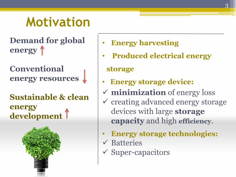
Motivation
• Energy harvesting
• Produced electrical energy
storage
• Energy storage device:
minimization of energy loss creating advanced energy storage
devices with large storage capacity and high efficiency.
• Energy storage technologies:
Batteries Super-capacitors
3
Demand for global energy Conventional energy resources Sustainable & clean energy development
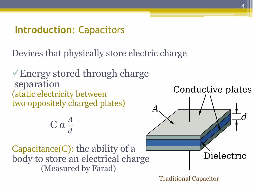
Introduction: Capacitors
Devices that physically store electric charge
Energy stored through charge separation (static electricity between two oppositely charged plates)
C α 𝐴
𝑑
Capacitance(C): the ability of a body to store an electrical charge (Measured by Farad)
Traditional Capacitor
4
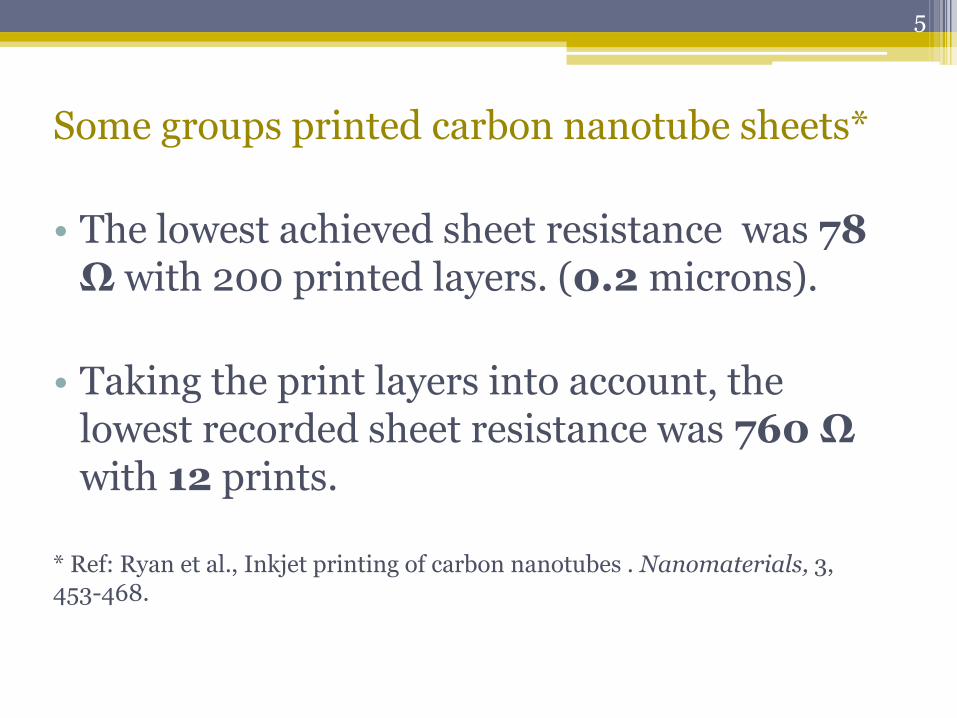
Some groups printed carbon nanotube sheets*
• The lowest achieved sheet resistance was 78 Ω with 200 printed layers. (0.2 microns).
• Taking the print layers into account, the lowest recorded sheet resistance was 760 Ω with 12 prints.
* Ref: Ryan et al., Inkjet printing of carbon nanotubes . Nanomaterials, 3, 453-468.
5
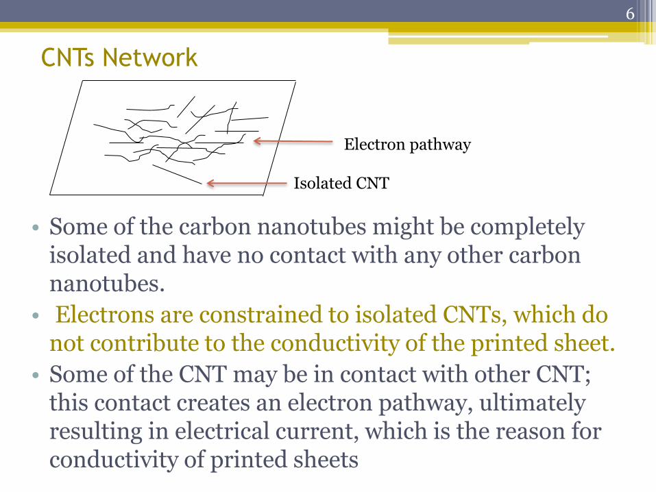
• Some of the carbon nanotubes might be completely isolated and have no contact with any other carbon nanotubes.
• Electrons are constrained to isolated CNTs, which do not contribute to the conductivity of the printed sheet.
• Some of the CNT may be in contact with other CNT; this contact creates an electron pathway, ultimately resulting in electrical current, which is the reason for conductivity of printed sheets
Electron pathway
Isolated CNT
CNTs Network
6
Hypothesis
* Addition of silver flake ink and silver nanowires into a CNT ink, used for printing the electrode layers of capacitor, will improve the device capacitance: • Lacing and eliminating the isolated tubes of
CNT • Conductivity of silver is very high which will
improve the conductivity of the CNT sheet conductivity
7
Cont. Hypothesis
*Calendering the electrode layers using
different pressure values would smooth the
film surface, eliminate and flatten the
peaks resulting from the protruding CNTs.
8
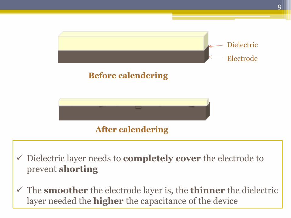
Before calendering
Electrode
Dielectric
After calendering
Dielectric layer needs to completely cover the electrode to
prevent shorting The smoother the electrode layer is, the thinner the dielectric
layer needed the higher the capacitance of the device
9
Research objectives
• optimize silver percentage and structure (nano-
wires or silver flake) added to CNT ink on the sheet
conductivity.
• Study the influence of calendering the multi-layer
capacitor electrodes.
• Fabricate multi-layer capacitors.
• Formulate carbon ink from a synthetic graphite
powder and conductive carbon black powder.
10
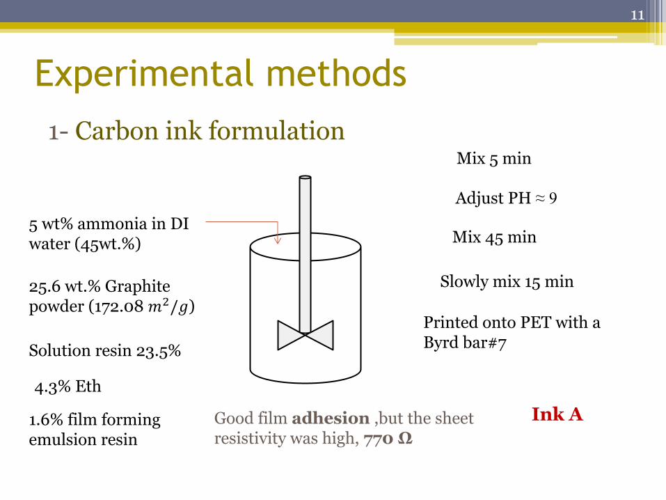
Experimental methods
1- Carbon ink formulation
5 wt% ammonia in DI water (45wt.%)
25.6 wt.% Graphite powder (172.08 𝑚2/𝑔)
Mix 5 min
Adjust PH ≈ 9
Solution resin 23.5%
4.3% Eth
Mix 45 min
1.6% film forming emulsion resin
Slowly mix 15 min
Printed onto PET with a Byrd bar#7
Good film adhesion ,but the sheet resistivity was high, 770 Ω
Ink A
11
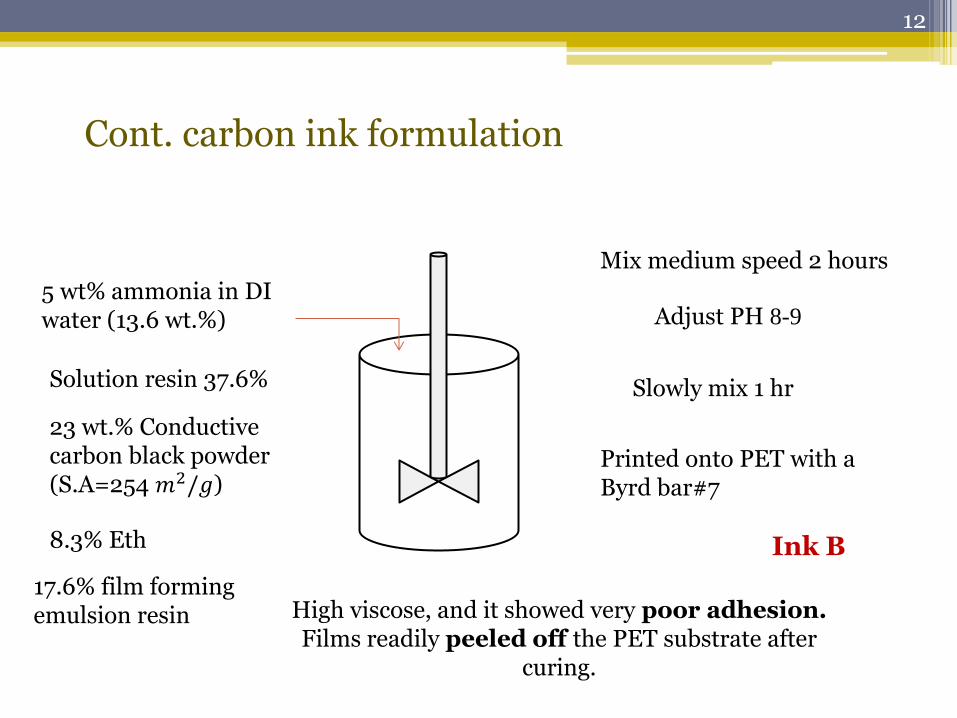
Cont. carbon ink formulation
5 wt% ammonia in DI water (13.6 wt.%)
23 wt.% Conductive carbon black powder (S.A=254 𝑚2/𝑔)
Mix medium speed 2 hours
Adjust PH 8-9
Solution resin 37.6%
8.3% Eth
Slowly mix 1 hr
17.6% film forming emulsion resin
Printed onto PET with a Byrd bar#7
High viscose, and it showed very poor adhesion. Films readily peeled off the PET substrate after
curing.
Ink B
12
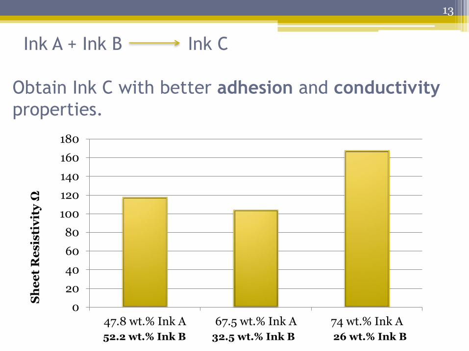
Ink A + Ink B Ink C
Obtain Ink C with better adhesion and conductivity
properties.
0
20
40
60
80
100
120
140
160
180
47.8 wt.% Ink A 67.5 wt.% Ink A 74 wt.% Ink A
Sh
ee
t R
es
isti
vit
y Ω
52.2 wt.% Ink B 32.5 wt.% Ink B 26 wt.% Ink B
13
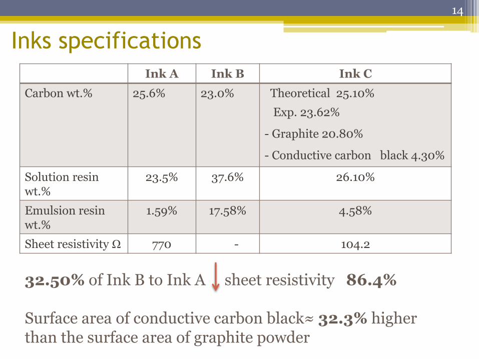
Inks specifications
Ink A Ink B Ink C
Carbon wt.% 25.6% 23.0% Theoretical 25.10%
Exp. 23.62%
- Graphite 20.80%
- Conductive carbon black 4.30%
Solution resin wt.%
23.5% 37.6% 26.10%
Emulsion resin wt.%
1.59% 17.58% 4.58%
Sheet resistivity Ω 770 - 104.2
32.50% of Ink B to Ink A sheet resistivity 86.4% Surface area of conductive carbon black≈ 32.3% higher than the surface area of graphite powder
14
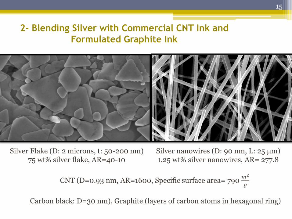
2- Blending Silver with Commercial CNT Ink and
Formulated Graphite Ink
Silver Flake (D: 2 microns, t: 50-200 nm) 75 wt% silver flake, AR=40-10
Silver nanowires (D: 90 nm, L: 25 μm) 1.25 wt% silver nanowires, AR= 277.8
CNT (D=0.93 nm, AR=1600, Specific surface area= 790 𝑚2
𝑔
Carbon black: D=30 nm), Graphite (layers of carbon atoms in hexagonal ring)
15
Ink blends preparation: (Manually mixed)
Graphite ink + Silver flake ink
Silver wt.%: 5, 10, 15, 20, 25, 30, and 35 wt.%
CNT ink + silver nanowires
Silver wt.%: 2, 5, 8, 10, 20, and 30 wt%
CNT ink + Silver flake
Silver wt.%: 5, 10, 20, 35, 50, 75, and 90 wt.%
For instance , a blend of 10 wt.% of silver nanowire in CNT was prepared by adding 7.56 ml silver nanowire to
8.5 g CNT ink
16
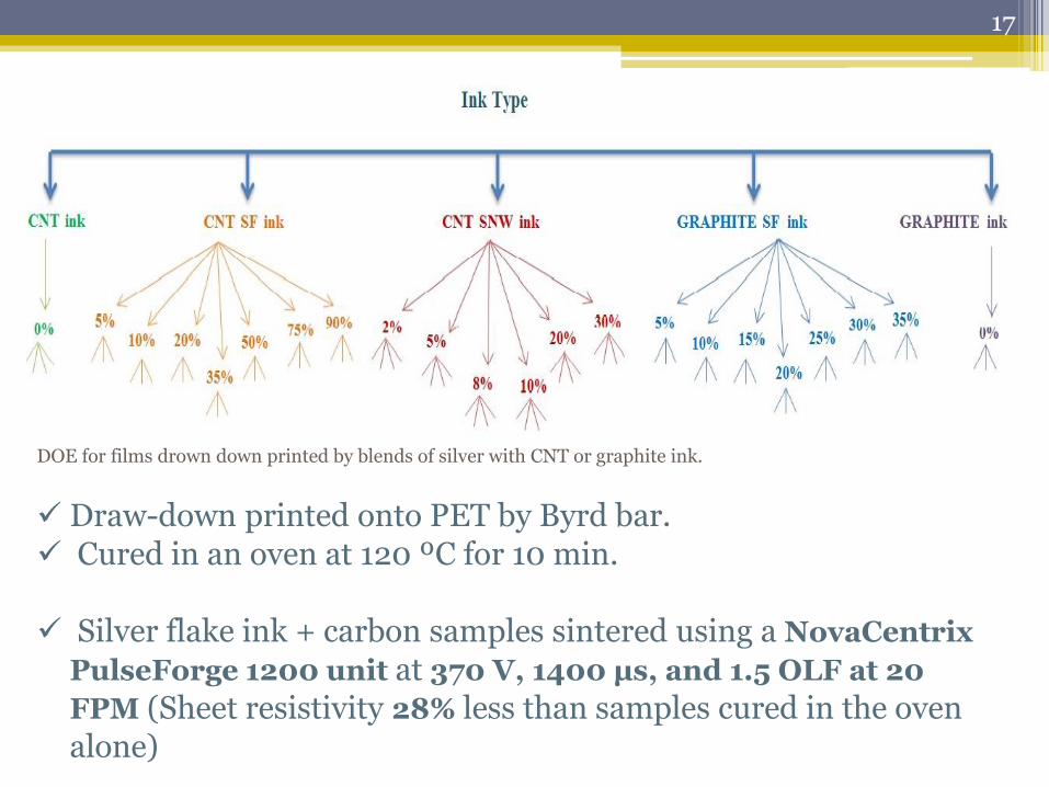
DOE for films drown down printed by blends of silver with CNT or graphite ink.
Draw-down printed onto PET by Byrd bar. Cured in an oven at 120 ºC for 10 min. Silver flake ink + carbon samples sintered using a NovaCentrix
PulseForge 1200 unit at 370 V, 1400 μs, and 1.5 OLF at 20
FPM (Sheet resistivity 28% less than samples cured in the oven alone)
17
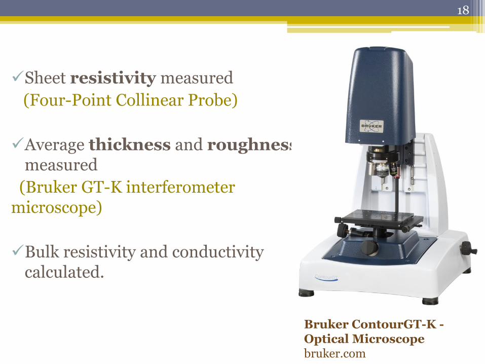
Sheet resistivity measured
(Four-Point Collinear Probe)
Average thickness and roughness measured
(Bruker GT-K interferometer microscope)
Bulk resistivity and conductivity calculated.
Bruker ContourGT-K - Optical Microscope bruker.com
18
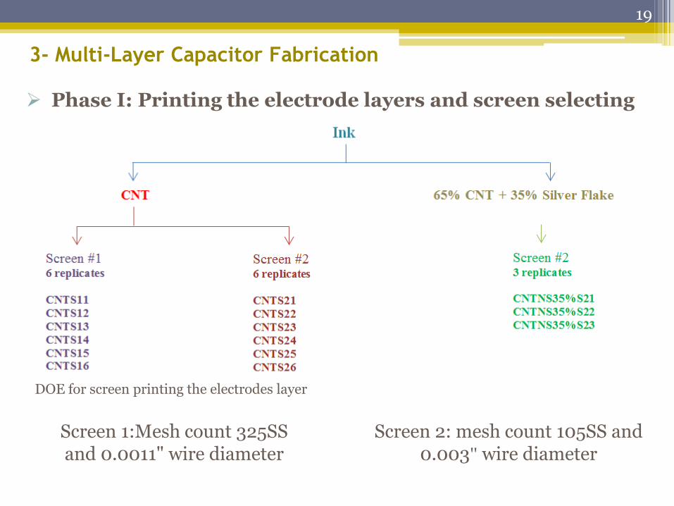
3- Multi-Layer Capacitor Fabrication
Phase I: Printing the electrode layers and screen selecting
DOE for screen printing the electrodes layer
Screen 1:Mesh count 325SS and 0.0011" wire diameter
Screen 2: mesh count 105SS and 0.003" wire diameter
19
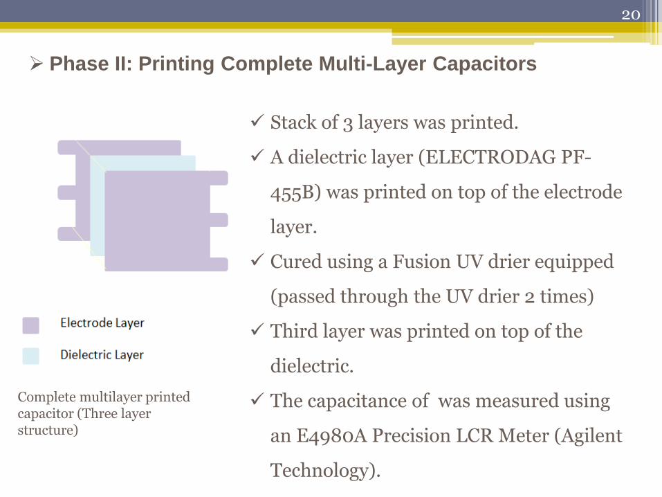
Phase II: Printing Complete Multi-Layer Capacitors
Stack of 3 layers was printed.
A dielectric layer (ELECTRODAG PF-
455B) was printed on top of the electrode
layer.
Cured using a Fusion UV drier equipped
(passed through the UV drier 2 times)
Third layer was printed on top of the
dielectric.
The capacitance of was measured using
an E4980A Precision LCR Meter (Agilent
Technology).
Complete multilayer printed capacitor (Three layer structure)
20
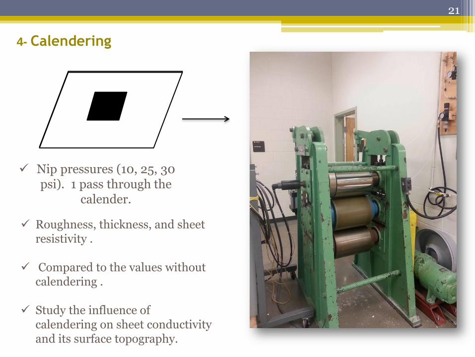
4- Calendering
Nip pressures (10, 25, 30 psi). 1 pass through the
calender.
Roughness, thickness, and sheet resistivity .
Compared to the values without
calendering . Study the influence of
calendering on sheet conductivity and its surface topography.
21
Results and Discussion
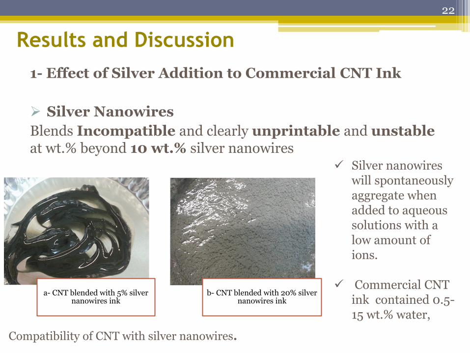
1- Effect of Silver Addition to Commercial CNT Ink
Silver Nanowires
Blends Incompatible and clearly unprintable and unstable at wt.% beyond 10 wt.% silver nanowires
a- CNT blended with 5% silver nanowires ink
b- CNT blended with 20% silver nanowires ink
Compatibility of CNT with silver nanowires.
Silver nanowires will spontaneously aggregate when added to aqueous solutions with a low amount of ions.
Commercial CNT ink contained 0.5-15 wt.% water,
22
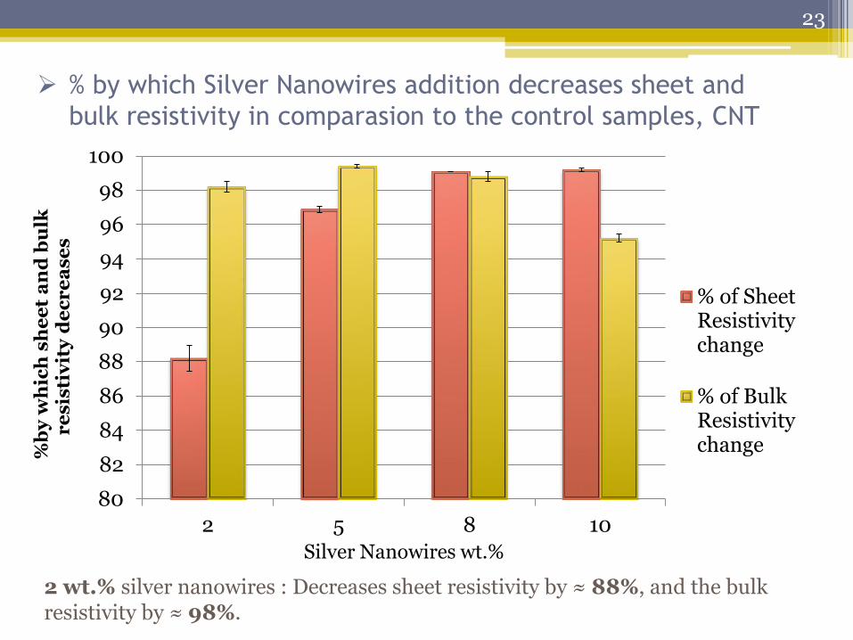
% by which Silver Nanowires addition decreases sheet and
bulk resistivity in comparasion to the control samples, CNT
80
82
84
86
88
90
92
94
96
98
100
2 5 8 10
%b
y w
hic
h s
he
et
an
d b
ulk
r
es
isti
vit
y d
ec
re
ase
s
Silver Nanowires wt.%
% of SheetResistivitychange
% of BulkResistivitychange
2 wt.% silver nanowires : Decreases sheet resistivity by ≈ 88%, and the bulk resistivity by ≈ 98%.
23
0.00
20.00
40.00
60.00
80.00
100.00
120.00
140.00
160.00
0 2 4 6 8 10 12
Sh
ee
t R
es
isti
vit
y (
Ω/□
)
Silver nanowires wt.% in ink
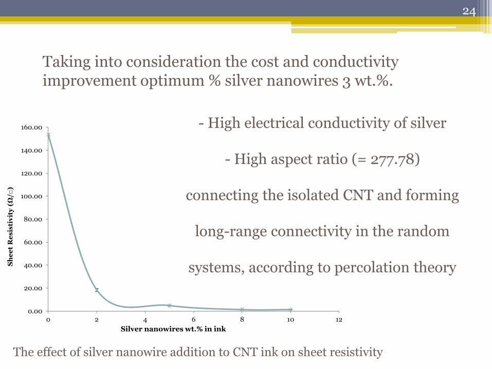
The effect of silver nanowire addition to CNT ink on sheet resistivity
Taking into consideration the cost and conductivity improvement optimum % silver nanowires 3 wt.%.
- High electrical conductivity of silver
- High aspect ratio (= 277.78)
connecting the isolated CNT and forming
long-range connectivity in the random
systems, according to percolation theory
24
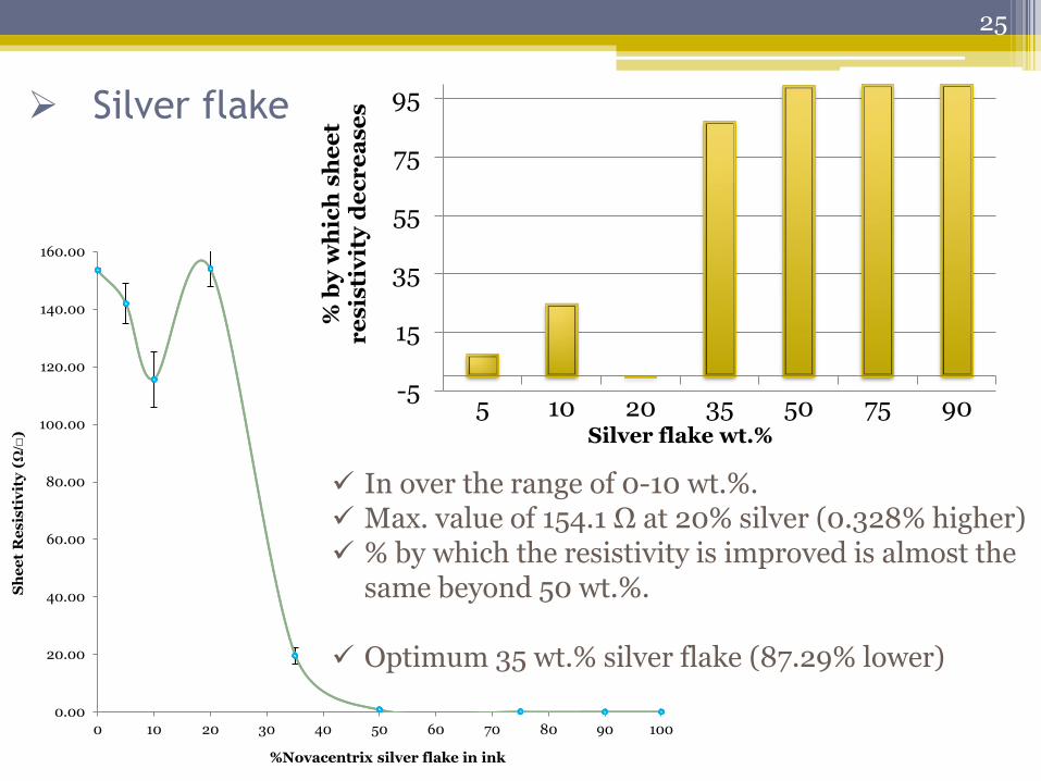
Silver flake
0.00
20.00
40.00
60.00
80.00
100.00
120.00
140.00
160.00
0 10 20 30 40 50 60 70 80 90 100
Sh
ee
t R
es
isti
vit
y (Ω
/□)
%Novacentrix silver flake in ink
In over the range of 0-10 wt.%. Max. value of 154.1 Ω at 20% silver (0.328% higher) % by which the resistivity is improved is almost the
same beyond 50 wt.%. Optimum 35 wt.% silver flake (87.29% lower)
-5
15
35
55
75
95
5 10 20 35 50 75 90
% b
y w
hic
h s
he
et
re
sis
tiv
ity
de
cr
ea
se
s
Silver flake wt.%
25
0.000000
0.005000
0.010000
0.015000
0.020000
0 10 20 30 40 50 60 70 80 90 100
Bu
lk R
es
isti
vit
y (
Ω.c
m)
-650
-550
-450
-350
-250
-150
-50
50
150
5 10 20 35 50 75 90
% b
y w
hic
h b
ulk
re
sis
tiv
ity
d
ec
re
as
es
or
in
cr
ea
se
s
Silver flake wt.%
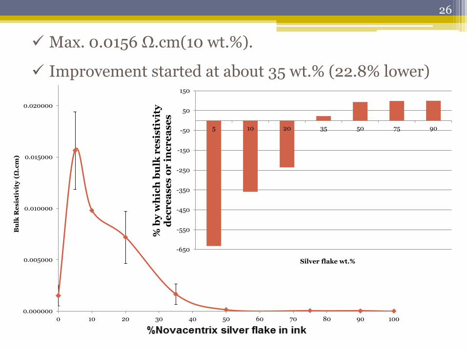
Max. 0.0156 Ω.cm(10 wt.%).
Improvement started at about 35 wt.% (22.8% lower)
26
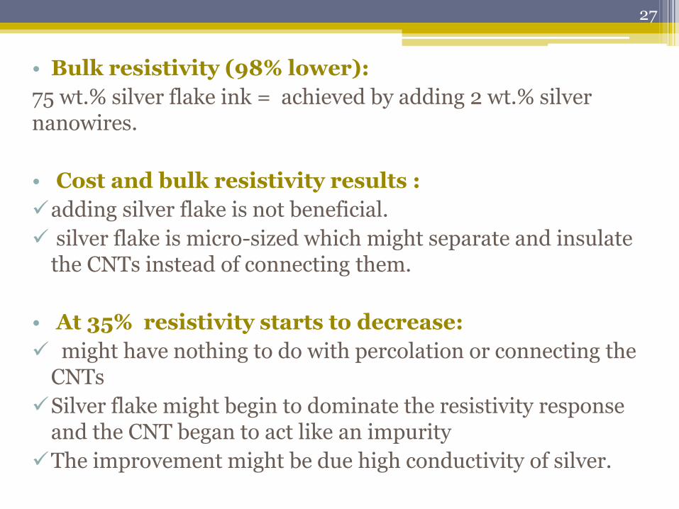
• Bulk resistivity (98% lower):
75 wt.% silver flake ink = achieved by adding 2 wt.% silver nanowires.
• Cost and bulk resistivity results :
adding silver flake is not beneficial.
silver flake is micro-sized which might separate and insulate the CNTs instead of connecting them.
• At 35% resistivity starts to decrease:
might have nothing to do with percolation or connecting the CNTs
Silver flake might begin to dominate the resistivity response and the CNT began to act like an impurity
The improvement might be due high conductivity of silver.
27
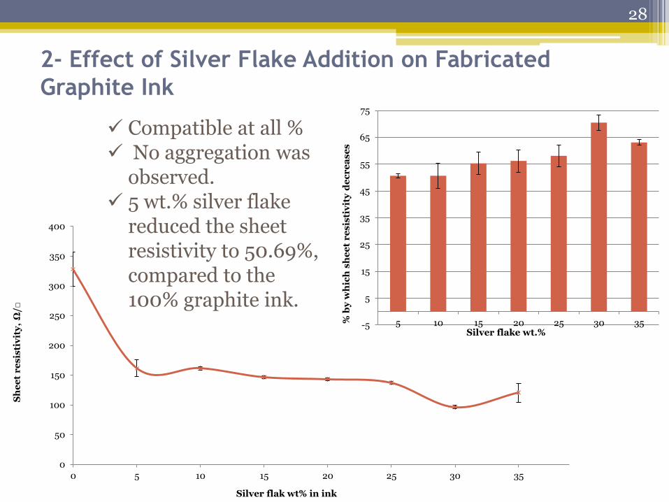
2- Effect of Silver Flake Addition on Fabricated
Graphite Ink
0
50
100
150
200
250
300
350
400
0 5 10 15 20 25 30 35
Sh
ee
t r
es
isti
vit
y,
Ω/□
Silver flak wt% in ink
-5
5
15
25
35
45
55
65
75
5 10 15 20 25 30 35% b
y w
hic
h s
he
et
re
sis
tiv
ity
de
cr
ea
se
s
Silver flake wt.%
Compatible at all % No aggregation was
observed. 5 wt.% silver flake
reduced the sheet resistivity to 50.69%, compared to the 100% graphite ink.
28
0
0.1
0.2
0.3
0.4
0.5
0.6
0 5 10 15 20 25 30 35
Bu
lk r
es
isti
vit
y,
Ω.c
m
Silver flake wt.% in ink
0
10
20
30
40
50
60
70
80
5 10 15 20 25 30 35
% b
y w
hic
h b
ulk
re
sis
tiv
ity
de
cr
es
es
Silver flake wt.%
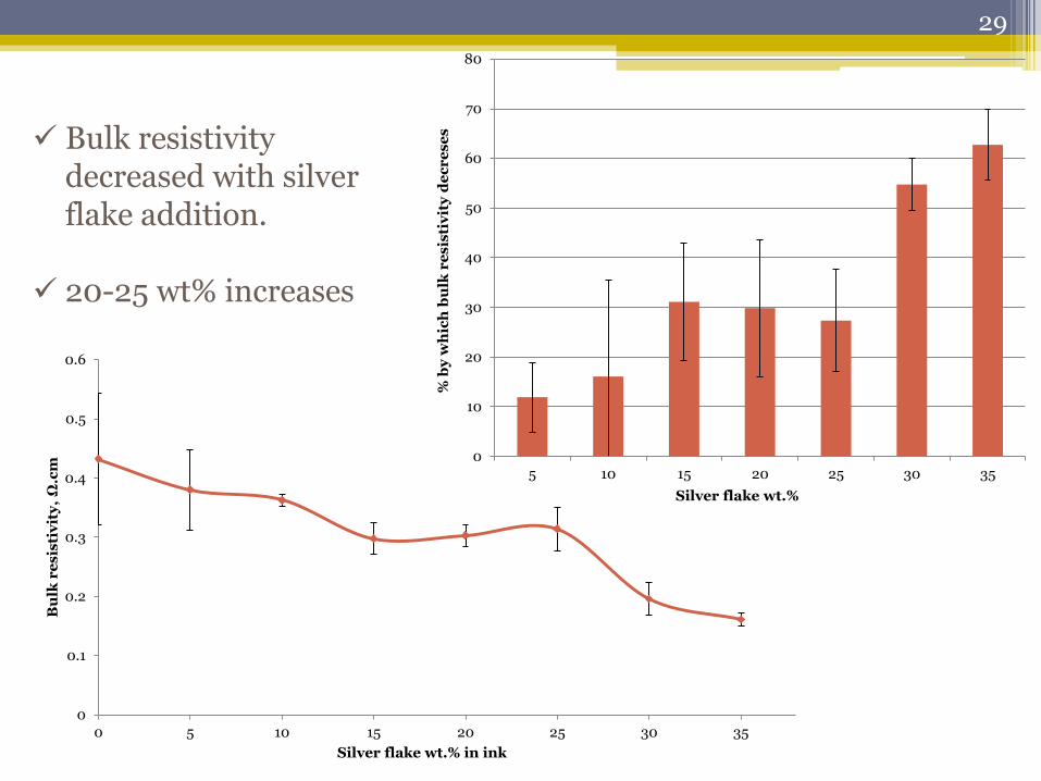
Bulk resistivity decreased with silver flake addition.
20-25 wt% increases
29
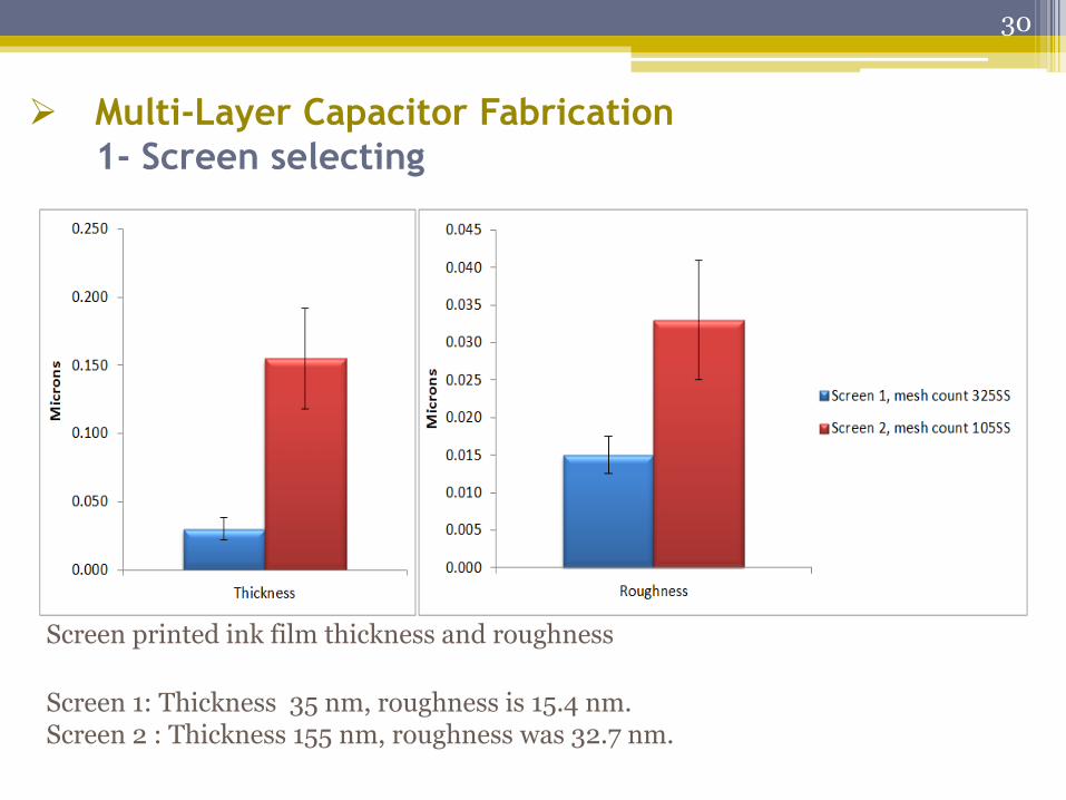
Multi-Layer Capacitor Fabrication
1- Screen selecting
Screen printed ink film thickness and roughness
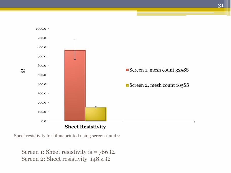
Screen 1: Thickness 35 nm, roughness is 15.4 nm. Screen 2 : Thickness 155 nm, roughness was 32.7 nm.
30
0.0
100.0
200.0
300.0
400.0
500.0
600.0
700.0
800.0
900.0
1000.0
Sheet Resistivity
Ω
Screen 1, mesh count 325SS
Screen 2, mesh count 105SS
Screen 1: Sheet resistivity is ≈ 766 Ω. Screen 2: Sheet resistivity 148.4 Ω
Sheet resistivity for films printed using screen 1 and 2
31
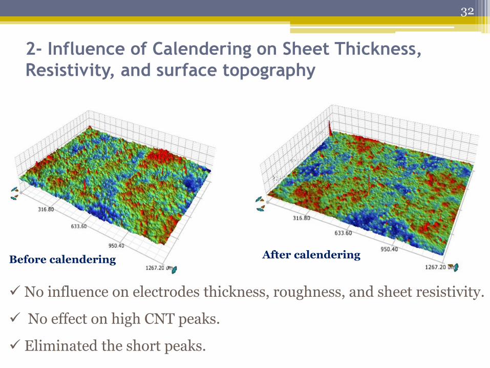
2- Influence of Calendering on Sheet Thickness,
Resistivity, and surface topography
No influence on electrodes thickness, roughness, and sheet resistivity.
No effect on high CNT peaks.
Eliminated the short peaks.
Before calendering After calendering
32
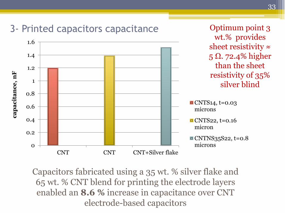
3- Printed capacitors capacitance
0
0.2
0.4
0.6
0.8
1
1.2
1.4
1.6
CNT CNT CNT+Silver flake
ca
pa
cit
an
ce
, n
F
CNTS14, t=0.03microns
CNTS22, t=0.16micron
CNTNS35S22, t=0.8microns
Capacitors fabricated using a 35 wt. % silver flake and 65 wt. % CNT blend for printing the electrode layers enabled an 8.6 % increase in capacitance over CNT
electrode-based capacitors
Optimum point 3 wt.% provides
sheet resistivity ≈ 5 Ω. 72.4% higher
than the sheet resistivity of 35%
silver blind
33
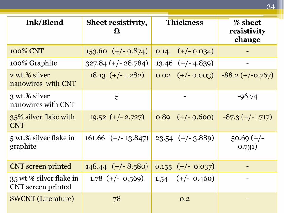
Ink/Blend Sheet resistivity, Ω
Thickness % sheet resistivity
change
100% CNT 153.60 (+/- 0.874) 0.14 (+/- 0.034) -
100% Graphite 327.84 (+/- 28.784) 13.46 (+/- 4.839) -
2 wt.% silver nanowires with CNT
18.13 (+/- 1.282) 0.02 (+/- 0.003) -88.2 (+/-0.767)
3 wt.% silver nanowires with CNT
5 - -96.74
35% silver flake with CNT
19.52 (+/- 2.727) 0.89 (+/- 0.600) -87.3 (+/-1.717)
5 wt.% silver flake in graphite
161.66 (+/- 13.847) 23.54 (+/- 3.889) 50.69 (+/- 0.731)
CNT screen printed 148.44 (+/- 8.580) 0.155 (+/- 0.037) -
35 wt.% silver flake in CNT screen printed
1.78 (+/- 0.569) 1.54 (+/- 0.460) -
SWCNT (Literature) 78 0.2 -
34
Conclusion • Ink was formulated from graphite powder (327.8 Ω, 0.432
Ω.cm).
• Commercial CNT ink (153.6 Ω,0.002 Ω.cm)
• To compare the two inks:
CNT has a sheet resistivity about 53% higher than formulated ink.
bulk resistivity 99.5% higher than formulated ink.
CNT is more conductive, but it is more expensive.
• By adding 5 wt.% silver flake to Ink C, sheet resistivity was
reduced 50.7% and its bulk resistivity was decreased 12%.
35
• By adding 5 wt.% silver flake to CNT ink, sheet
resistivity was reduced 7.5% and bulk resistivity
increased by 632.6%.
• Adding silver flake to synthetic graphite ink is
efficient. But adding it to CNT ink not effeciant.
• The optimum silver % in the CNT ink was found to
be 3 wt.% silver nanowires.
• Results showed that calendering did not improve the
conductivity of the CNT printed sheets.
36
Recommendations for future studies
• Mixing nano-sized silver particles with the CNT ink
instead of using larger micro-sized silver flake particles.
• Fabricating an ink from scratch using CNT and silver
nanowire powders to avoid any aggregation and
incompatibility issues.
• Finally, print a stacked capacitor with more than three
layers to increase overall capacitance.
37
Acknowledgements
• Dr. Margaret Joyce, professor, supervisor.
• Dr. Paul D. Fleming III, professor, committee member.
• Dr. Thomas Joyce, professor, committee member.
• Colleagues: Bhushan Hiralal Pati, Veronika Husovska,
James Atkinson, Michael Joyce, Ali Eshkeiti.
38
Recommended