Service Letter SL2015-597/HCL
Action code: AT FIRST OPPORTUNITY
MAN Diesel & TurboH. Christoffersensvej 64960 HolebyDenmarkPhone: +45 54 69 31 00Fax: +45 54 69 30 [email protected]
www.mandieselturbo.com
MAN Diesel & TurboNiels Juels Vej 159900 FrederikshavnDenmarkPhone: +45 96 20 41 00Fax: +45 96 20 40 [email protected]
MAN Diesel & TurboBranch of MAN Diesel & Turbo SE, GermanyCVR No.: 31611792Head office: Teglholmsgade 412450 Copenhagen SV, DenmarkGerman Reg.No.: HRB 22056Amtsgericht Augsburg
Dear Sirs
Service experience from vessels operating on heavy fuel oil, which is the most common fuel on many vessels, has shown that insufficient cleaning of the turbocharger will eventually result in a decreasing tur-bocharger performance.
Fouling of the turbine side of the turbocharger is a common cause for high exhaust gas temperatures.
The sequence of events is often as follows:
Fouling of turbine (coke deposit)
Bad turbocharger performance
Lower airflow and charge air pressure
Higher exhaust gas temperatures.
Fouling of the turbine and, consequently, a higher exhaust gas tem-perature is influenced by the:
• level of maintenance • condition of the fuel injection nozzles / fuel pumps • fuel oil quality • long-term low-load operation.
Service experience shows that proper and timely cleaning of the turbo-charger will result in good turbocharger performance, longer overhaul intervals and fuel consumption according to specified values.
Yours faithfully
Mikael C. Jensen Vice PresidentEngineering
Hans Christian LauritsenMechanical EngineerFour-stroke Maturing and Field Testing
High Exhaust Gas Temperatures andTurbine Cleaning SL2015-597/HCLMarch 2015
ConcernsOwners and operators of MAN four-stroke diesel engines.GenSets type: L16/24, L21/31, L23/30H, L27/38, L28/32H, V28/32S
Attachments:
Description 501.15 (03)/601.15 (03H), Guidelines
for longterm low-load operation on HFO
Description 512.14 (01)/612.14 (01H), Cleaning the
turbocharger in service - turbine side
Work Card 512-10.00 (05)/612-10.00 (03H), Clean-
ing the turbine, dry cleaning
Work Card 512-15.00 (05)/612-15.00 (03H), Water
washing of turbine side
Plate 51215-04/61215-01H, Water washing of tur-
bine side
New standard for HFO engines is a combination of dry cleaning and water washing of turbine side
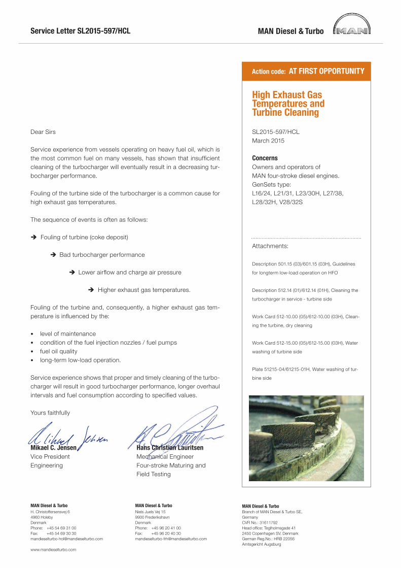
No further action is needed for engines delivered with a pip-ing arrangement for water washing. Other engines will need the newly developed tool for water washing of the turbine. The tool uses the same connection as for dry cleaning. For most engines no further changes are needed. Please con-tact PrimeServ MAN Diesel & Turbo for purchasing new wa-ter washing tool.
As not all injected water is evaporated, turbochargers need to be fitted with a drain from the exhaust gas outlet. For en-gines delivered without drain, customers of these engines must contact MAN Diesel & Turbo.
In this regard, please also note: Description 501.15 “Guidelines for long-term Low-load operation on HFO”Description 010.000.023-05: “Heavy fuel oil (HFO) specification”
The expected turbine cleaning intervals must be the follow-ing when operating on HFO: “D-D” Dry-cleaning Daily cleaning“W-W” Wet-cleaning Weekly Cleaning intervals can be shorter/longer based on opera-tional experience. Regular performance observations will show the trend in charge air pressure and exhaust gas tem-peratures, and define the cleaning intervals for the turbine. However, the turbine must be cleaned when exhaust gas temperature before turbine are about 20°C above the normal temperature (ISO corrected) (sea trial).
Due to the area-relation in matching parts, smaller turbo-chargers are more sensitive to coke deposits than larger turbochargers and, consequently, low-power engines such as the L16/24 or L23/30H will need more frequent turbine cleaning than more powerful engines.
Nutshell dry or Water washing cleaning has been the turbine cleaning method for many years. Recent service experience based on current emission stan-dars reveals that the turbocharger must always be in good condition to obtain the expected engine performance.
Service Letter SL2015-597/HCL
High Exhaust Gas Temperatures and Turbine Cleaning Page 2 of 2
Tool for cleaning of turbine
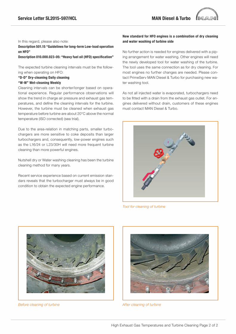
Before cleaning of turbine After cleaning of turbine

Description
High exhaust gas temperatures are often observedand claimed in service. High exhaust gas tempera-tures are normally caused by fouling on the turbineside of the turbocharger:➣ Fouling turbine (coke deposit)
➭ Lower turbocharger performance
➭ Lower air flow / pressure through the engine
➭ Increasing exhaust gas temperatures
➭ Increasing fuel oil consumption
Fouling of the turbine and consequently higherexhaust gas temperature is influenced by: level ofmaintenance, condition of the fuel injection noz-zles / fuel pumps, fuel oil quality and/or long-termlow-load operation.
Smaller turbochargers are, due to area-relation inmatching parts, more sensitive to coke deposit thanlarger turbochargers and consequently low powerengines as L16/24 or L23/30H will need turbinecleaning more frequent than more powerfulengines.
Turbine cleaning intervals must be expected to befollowing when operating on HFO: “D-D” Dry-cleaning Daily Cleaning “W-W” Wet-cleaning Weekly Cleaning intervals can be shorter/longer based onoperational experience. Regular performanceobservations will show the trend in charge air pres-sure, exhaust gas temperatures, and define thecleaning intervals for the turbine. However the tur-bine must be cleaned when exhaust gas tempera-ture before turbine are about 20°C above the nor-mal temperature (ISO corrected) (Sea trial).
Practical service experience have revealed that tur-bine side of turbocharger only can be sufficientcleaned by combination of nut-shell dry cleaningand water washing.
Dry cleaning of turbine side
This cleaning method employs cleaning agents con-sisting of dry solid bodies in the form of granules. Acertain amount of these granules, depending on theturbocharger size, is, by means of compressed air,blown into the exhaust gas line before the gas inletcasing of the turbocharger.
The injection of granules is done by means of work-ing air with a pressure of 5-7 bar.
On account of their hardness, particularly suitedblasting agents such as nut-shells, broken or artifi-cially shaped activated charcoal with a grain size of1.0 mm to max. 1.5 mm should be used as clean-ing a gents.
The solid bodies have a mechanical cleaning effectwhich removes any deposits on nozzle vanes andturbine blades.
Dry cleaning can be executed at full engine loadand does not require any subsequent operatingperiod of the engine in order to dry out the exhaustsystem.
MAN Diesel & Turbo
DescriptionPage 1 (6) Cleaning the turbocharger in service - turbine side
512.14Edition 01
L16/24, L23/30H, V28/32S, L21/31, L27/38, L16/24S, L21/31S, L23/30S, L27/38S,
L28/32S
2015.03.02

Cleaning system
The cleaning system consists of a cleaning agentcontainer (2) with a capacity of approx. 0.5 litersand a removable cover. Furthermore the systemconsists of an air valve (3), a closing valve (1) andtwo snap on connectors.
The position numbers (2) and (3) indicate the sys-tem's "blow-gun". Only one "blow-gun" is used foreach engine plant. The blow-gun is working accord-ing to the ejector principle with pressure air (workingair) at 5-7 bar as driven medium. Injection timeapprox. 2 min. Air consumption approx. 5 Nm3/2min.
1 Closing valve 2 Container
3 Air valve 4 Working air inlet
5 Exhaust pipe 6 Snap coupling
Figure 1: Arrangement of dry cleaning of turbocharger - turbine
MAN Diesel & Turbo512.14
Edition 01Cleaning the turbocharger in service - turbine side Description
Page 2 (6)
L16/24, L23/30H, V28/32S, L21/31, L27/38, L16/24S, L21/31S, L23/30S, L27/38S,L28/32S
2015.03.02

MAN Diesel & Turbo
DescriptionPage 3 (6) Cleaning the turbocharger in service - turbine side
512.14Edition 01
L16/24, L23/30H, V28/32S, L21/31, L27/38, L16/24S, L21/31S, L23/30S, L27/38S,
L28/32S
2015.03.02

MAN Diesel & Turbo512.14
Edition 01Cleaning the turbocharger in service - turbine side Description
Page 4 (6)
L16/24, L23/30H, V28/32S, L21/31, L27/38, L16/24S, L21/31S, L23/30S, L27/38S,L28/32S
2015.03.02

Water washing of turbine side
The necessary water flow is depending on exhaustgas flow and temperature. E.g. the flow needed forL16/24 is from 2 - 5 litres per minute for 5 and 9cylinder engines. The water flow must be so highthat all of the water do not evaporate. Also thewaterflow must not be so high that the turbinewheel is drowned and stops rotating. The washingsequence should be in accordance with the turbo-charger manual. Engine load, exhaust gas tempera-ture before turbine and turbine speed must beaccording to turbocharger manual. Carry outsequential washing so that exhaust gas tempera-ture after turbine drops below 100°C and in the dry-ing period increases to more than 100°C. For pre-adjustment of the washing tool, install the correctorifice for the actual engine size, check that thewater flow is in accordance with the table by adjust-ing the water pressure. Check in a bucket that thewater flow is in the correct range.
Water flowl/min
Diameter orificemm
5-9L16/24 2-5 2.5
5-9L21/31 5-10 3.5
5L27/38 (NR20/S)5-6L27/38 (TCR18)
7-11 3.5
6-8L27/38 (NR24/S)7-9L27/38 (TCR20)
10-15 4.5
5-6L23/30H5-6L23/30H Mk2
2-5 2.5
7-8L23/30H7-8L23/30H Mk2
4-7 3.5
12V28/32S 5-10 3.5
16-18V28/32S 7-11 3.5
Experience has shown, that washing at regularintervals is essential to successful cleaning, asexcessive fouling is thus avoided. Washing at inter-vals of 100 hours is therefore recommended.Depending on the fuel quality these intervals can beshorter or longer. However, the turbine must bewashed at the latest when the exhaust gas temper-ature upstream of the turbine has risen about 20° Cabove the normal temperature.
Heavily contaminated turbines, which where notcleaned periodically from the very beginning or afteran overhaul, cannot be cleaned by this method.
If vibration in the turbocharger occur after water-washing has been carried out, the washing shouldbe repeated. If unbalance still exists, this is presum-ably due to heavy fouling, and the engine must bestopped and the turbocharger dismantled and man-ually cleaned.
The cleaning effect is based on the water solubilityof the deposits and on the mechanical action of theimpinging water droplets and the water flow rate.
The washing water should be taken from the freshwater system and not from the fresh cooling watersystem or salt water system. No cleaning agentsand solvents need to be added to the water.
To avoid corrosion during standstill, the enginemust, upon completing of water washing run for atleast 1 hour before stop to insure that all parts aredry.
Water washing arrangement / tool
Some customized engines are delivered with waterwashing arrangement consisting of a pipe systemwith a regulating valve, a manoeuvring valve, a 3-way cock and a drain pipe with a drain valve fromthe gas outlet, see illustration on work card512-15.00/612-15.00.
New engines are as standard delivered with "waterwashing gun" as a part of standard tools forengines. The tool can be seen in figure 2 and isusing the same connecting as the dry cleaning con-nection.
Figure 2: .
MAN Diesel & Turbo
DescriptionPage 5 (6) Cleaning the turbocharger in service - turbine side
512.14Edition 01
L16/24, L23/30H, V28/32S, L21/31, L27/38, L16/24S, L21/31S, L23/30S, L27/38S,
L28/32S
2015.03.02

The water for washing the turbine, is supplied fromthe external fresh water system through a flexiblehose with couplings. The flexible hose must be dis-connected after water washing.
By activating the maneuvering valve and the regu-lating valve the water is sprayed into the exhaustgas pipe before the turbine side of the turbo-charger. See specific work card for water washingof turbine side. The water that is not evaporated isled out through a drain pipe in the exhaust gas out-let.
MAN Diesel & Turbo512.14
Edition 01Cleaning the turbocharger in service - turbine side Description
Page 6 (6)
L16/24, L23/30H, V28/32S, L21/31, L27/38, L16/24S, L21/31S, L23/30S, L27/38S,L28/32S
2015.03.02

Part load/low load operation
Figure 1: Low-load operation
In certain ship and power station operation modesthe diesel generating sets are exposed to partload/low load operation.
During manoeuvring of the ship all diesel generatingsets are often started up for safety reasons, result-ing in low load operation of all the engines. Duringharbour stay one diesel generator could be low-loa-ded when only hotel purposes are consuming elec-tricity.
Island mode operation of diesel generating sets inpower stations is frequently exposed to low loadoperation like on a ship.
At part load/low load it is important to maintain con-stant media temperatures, i.e. for cooling water,lubricating oil and fuel oil in order to ensure ade-quate combustion chamber temperature and thuscomplete combustion.
At loads lower than 20% MCR there is a risk of timedependant retardation of the engine performancecondition due to fouling of the exhaust gas chan-
nels and combustion air channels, combustionchambers and turbocharger. HFO-operation atloads lower than 20% MCR should therefore onlytake place within certain time limitations accordingto the curves.
After a certain period of HFO-operation at loadslower than 20% MCR, a change to MDO shouldtake place in order to prevent further retardation ofthe engine performance condition. Alternatively, theengine load should be raised to 70% MCR over aperiod of 15 minutes and maintained here for sometime in order to burn off the carbon deposits, thusre-establishing adequate performance condition.After such a "clean burning period" low load opera-tion on HFO can be continued.
However, the operator must be aware of the factthat fouling in the combustion air inlet channels, ifany, will not be cleaned at high load operation.Extensive low load running can therefore result inthe need for manual cleaning of the combustion airinlet channels.
MAN Diesel & Turbo
DescriptionPage 1 (2) Guidelines for Longterm Low-Load Operation on HFO
601.15Edition 03H
L28/32H, V28/32H
2008.05.12

If special application conditions require continuousHFO-operation at loads lower than 20% MCR andoccasionally performed "clean-burning" periods areinconvenient or impossible, special equipment andarrangements must be established.
MAN Diesel & Turbo601.15
Edition 03HGuidelines for Longterm Low-Load Operation on HFO Description
Page 2 (2)
L28/32H, V28/32H
2008.05.12

Description
High exhaust gas temperatures are often observedand claimed in service. High exhaust gas tempera-tures are normally caused by fouling on the turbineside of the turbocharger:➣ Fouling turbine (coke deposit)
➭ Lower turbocharger performance
➭ Lower air flow / pressure through the engine
➭ Increasing exhaust gas temperatures
➭ Increasing fuel oil consumption
Fouling of the turbine and consequently higherexhaust gas temperature is influenced by: level ofmaintenance, condition of the fuel injection noz-zles / fuel pumps, fuel oil quality and/or long-termlow-load operation.
Smaller turbochargers are, due to area-relation inmatching parts, more sensitive to coke deposit thanlarger turbochargers and consequently low powerengines as L16/24 or L23/30H will need turbinecleaning more frequent than more powerfulengines.
Turbine cleaning intervals must be expected to befollowing when operating on HFO: “D-D” Dry-cleaning Daily Cleaning “W-W” Wet-cleaning Weekly Cleaning intervals can be shorter/longer based onoperational experience. Regular performanceobservations will show the trend in charge air pres-sure, exhaust gas temperatures, and define thecleaning intervals for the turbine. However the tur-bine must be cleaned when exhaust gas tempera-ture before turbine are about 20°C above the nor-mal temperature (ISO corrected) (Sea trial).
Practical service experience have revealed that tur-bine side of turbocharger only can be sufficientcleaned by combination of nut-shell dry cleaningand water washing.
Dry cleaning of turbine side
This cleaning method employs cleaning agents con-sisting of dry solid bodies in the form of granules. Acertain amount of these granules, depending on theturbocharger size, is, by means of compressed air,blown into the exhaust gas line before the gas inletcasing of the turbocharger.
The injection of granules is done by means of work-ing air with a pressure of 5-7 bar.
On account of their hardness, particularly suitedblasting agents such as nut-shells, broken or artifi-cially shaped activated charcoal with a grain size of1.0 mm to max. 1.5 mm should be used as clean-ing a gents.
The solid bodies have a mechanical cleaning effectwhich removes any deposits on nozzle vanes andturbine blades.
Dry cleaning can be executed at full engine loadand does not require any subsequent operatingperiod of the engine in order to dry out the exhaustsystem.
MAN Diesel & Turbo
DescriptionPage 1 (6) Cleaning the turbocharger in service - turbine side
612.14Edition 01H
L28/32H
2015.03.02

Cleaning system
The cleaning system consists of a cleaning agentcontainer (2) with a capacity of approx. 0.5 litersand a removable cover. Furthermore the systemconsists of an air valve (3), a closing valve (1) andtwo snap on connectors.
The position numbers (2) and (3) indicate the sys-tem's "blow-gun". Only one "blow-gun" is used foreach engine plant. The blow-gun is working accord-ing to the ejector principle with pressure air (workingair) at 5-7 bar as driven medium. Injection timeapprox. 2 min. Air consumption approx. 5 Nm3/2min.
1 Closing valve 2 Container
3 Air valve 4 Working air inlet
5 Exhaust pipe 6 Snap coupling
Figure 1: Arrangement of dry cleaning of turbocharger - turbine
MAN Diesel & Turbo612.14
Edition 01HCleaning the turbocharger in service - turbine side Description
Page 2 (6)
L28/32H
2015.03.02

MAN Diesel & Turbo
DescriptionPage 3 (6) Cleaning the turbocharger in service - turbine side
612.14Edition 01H
L28/32H
2015.03.02

MAN Diesel & Turbo612.14
Edition 01HCleaning the turbocharger in service - turbine side Description
Page 4 (6)
L28/32H
2015.03.02

Water washing of turbine side
The necessary water flow is depending on exhaustgas flow and temperature. E.g. the flow needed forL28/32H is from 5-10 litres per minute for 5 and 6cylinder engines. The water flow must be so highthat all of the water do not evaporate. Also thewaterflow must not be so high that the turbinewheel is drowned and stops rotating. The washingsequence should be in accordance with the turbo-charger manual. Engine load, exhaust gas tempera-ture before turbine and turbine speed must beaccording to turbocharger manual. Carry outsequential washing so that exhaust gas tempera-ture after turbine drops below 100°C and in the dry-ing period increases to more than 100°C. For pre-adjustment of the washing tool, install the correctorifice for the actual engine size, check that thewater flow is in accordance with the table by adjust-ing the water pressure. Check in a bucket that thewater flow is in the correct range.
Water flowl/min
Diameter orificemm
5-6L28/32H 5-10 3.5
7-9L28/32H 7-11 3.5
Experience has shown, that washing at regularintervals is essential to successful cleaning, asexcessive fouling is thus avoided. Washing at inter-vals of 100 hours is therefore recommended.Depending on the fuel quality these intervals can beshorter or longer. However, the turbine must bewashed at the latest when the exhaust gas temper-ature upstream of the turbine has risen about 20° Cabove the normal temperature.
Heavily contaminated turbines, which where notcleaned periodically from the very beginning or afteran overhaul, cannot be cleaned by this method.
If vibration in the turbocharger occur after water-washing has been carried out, the washing shouldbe repeated. If unbalance still exists, this is presum-ably due to heavy fouling, and the engine must bestopped and the turbocharger dismantled and man-ually cleaned.
The cleaning effect is based on the water solubilityof the deposits and on the mechanical action of theimpinging water droplets and the water flow rate.
The washing water should be taken from the freshwater system and not from the fresh cooling watersystem or salt water system. No cleaning agentsand solvents need to be added to the water.
To avoid corrosion during standstill, the enginemust, upon completing of water washing run for atleast 1 hour before stop to insure that all parts aredry.
Water washing arrangement / tool
Some customized engines are delivered with waterwashing arrangement consisting of a pipe systemwith a regulating valve, a manoeuvring valve, a 3-way cock and a drain pipe with a drain valve fromthe gas outlet, see illustration on work card512-15.00/612-15.00.
New engines are as standard delivered with "waterwashing gun" as a part of standard tools forengines. The tool can be seen in figure 2 and isusing the same connecting as the dry cleaning con-nection.
Figure 2: .
The water for washing the turbine, is supplied fromthe external fresh water system through a flexiblehose with couplings. The flexible hose must be dis-connected after water washing.
By activating the maneuvering valve and the regu-lating valve the water is sprayed into the exhaustgas pipe before the turbine side of the turbo-charger. See specific work card for water washing
MAN Diesel & Turbo
DescriptionPage 5 (6) Cleaning the turbocharger in service - turbine side
612.14Edition 01H
L28/32H
2015.03.02

of turbine side. The water that is not evaporated isled out through a drain pipe in the exhaust gas out-let.
MAN Diesel & Turbo612.14
Edition 01HCleaning the turbocharger in service - turbine side Description
Page 6 (6)
L28/32H
2015.03.02

Safety precautions
Engine stoppedShut-off starting airShut off cooling waterShut off fuel oilShut-off cooling oilStop lub. oil circulationPress Blocking - Reset
Short Description
Cleaning and/or maintenance of air filter.
Starting Position
Related Procedure
Qualified Manpower
Duration in h : 1/2Number : 1
Data
Data for pressure and tolerance (Page 500.35)Data for tightening torque (Page 500.40)Declaration of weight (Page 500.45)
Special tools
Plate No. Item No. Note51210 .
Hand Tools
Replacement and wearing parts
Plate No. Item No. Quantity
See specialinstruction for tur-bocharger
MAN Diesel & Turbo
Work CardPage 1 (2) Cleaning the Turbine, dry cleaning
512-10.00Edition 05
L16/24, L23/30H, V28/32S, L21/31, L27/38, L16/24S, L21/31S, L23/30S, L27/38S,
L28/32S
2015.03.03.

Health Risk!
Health Risk!
Due to vibrations during engine operation, espe-cially in awkward positions!
Dry cleaning
1 Stop valve 2 Container
3 Valve 4 Working air
Figure 1: Dry cleaning
Depending on the type of engine and turbocharger,the arrangement of items may also differ somewhatfrom that shown in the schematic.
Appropriate cleaning materials are granulates fromnut shells or activated charcoal of a grain size of 1mm (max. 1.5 mm)
Cleaning sequence
Please also consult the instruction plate on theengine.
The cleaning is to be carried out at high engineload, min. 75 % MCR.
1) Before connecting the cleaning device, see fig1, open the stop valve (1) and check that thepassage is not blocked. Close the valve again.
2) Fill the container (2) with granulate. The amountdepending on the type of turbocharger.
NR12, NR14, NR15, NR17, NR20 0.3 liters
NR24, NR26 0.4 liters
NR29, NR34 0.5 liters
3) Connect to the working air system (4).
4) Connect the dry cleaning device to valve (1)and open valve (3). Then open valve (1) slowlyuntil a hissing sound indicates that the granu-late is being injected. Injection period: Approx.2 min or until the container is empty.
Dry cleaning must be performed at all injection con-nections (if more than one).
Note: If vibrations occur after cleaning the turbine itis necessary to repeat the cleaning process until novibrations are observed.
MAN Diesel & Turbo512-10.00Edition 05
Cleaning the Turbine, dry cleaning Work CardPage 2 (2)
L16/24, L23/30H, V28/32S, L21/31, L27/38, L16/24S, L21/31S, L23/30S, L27/38S,L28/32S
2015.03.03.

Safety precautions
Engine stoppedShut-off starting airShut off cooling waterShut off fuel oilShut-off cooling oilStop lub. oil circulationPress Blocking - Reset
Short Description
Water washing of turbine side, cleaning withengine in service.
Starting Position
Related Procedure
Qualified Manpower
Duration in h : 1/2Number : 1
Data
Data for pressure and tolerance (Page 500.35)Data for tightening torque (Page 500.40)Declaration of weight (Page 500.45)
Special tools
Plate No. Item No. Note
Hand Tools
Replacement and wearing parts
Plate No. Item No. Quantity
See the specialinstruction for tur-bocharger.
MAN Diesel & Turbo
Work CardPage 1 (2) Water washing of turbine side
512-15.00Edition 05
L16/24, L23/30H, V28/32S, L21/31, L27/38, L16/24S, L21/31S, L23/30S, L27/38S,
L28/32S
2015.03.02

Cleaning procedure
1) See Description 512.20/612.20, "Cleaning ofturbocharger in service - turbine side", for pre-adjustment of washing tool.
2) Reduce the engine load to 0-15% and let theengine stabilize for 10 min. so that the exhaustgas temperature before T/C is below 320oC.
3) Open the drain cock at the turbocharger outletdrain pipe and check for free passage, see fig.1, pos. 1.
Figure 1: .
4) Turn valve, fig. 2, pos. 2, to position "Open"and check for free passage.
5) Connect the water supply to the water washinggun.
6) Connect the water washing gun to the valve,pos. 2.
7) Open the valve, see fig.2, pos. 3.Check water is coming out of the T/C drain;this might take some time (10-20 sec.).When the exhaust temperature after T/C dropsto below 100oC, close the water washing (pos.3) until the temperature after T/C has reached150oC.
8) Repeat the sequence until the drain watercoming out is clean (light grey) and free frombigger soot particles.
9) Close the valve (pos. 2) and check that thewater drain flow has stopped and disconnectthe water washing gun.
10) Continue at this load at least 10 min. beforeincreasing the load to the normal condition.
11) After the water washing, the engine should runfor at least 1 hour before stop.
Figure 2: .
MAN Diesel & Turbo512-15.00Edition 05
Water washing of turbine side Work CardPage 2 (2)
L16/24, L23/30H, V28/32S, L21/31, L27/38, L16/24S, L21/31S, L23/30S, L27/38S,L28/32S
2015.03.02

Safety precautions
Engine stoppedShut-off starting airShut off cooling waterShut off fuel oilShut-off cooling oilStop lub. oil circulationPress Blocking - Reset
Short Description
Cleaning and/or maintenance of air filter.
Starting Position
Related Procedure
Qualified Manpower
Duration in h : 1/2Number : 1
Data
Data for pressure and tolerance (600.35)Data for tightening torque (600.40)Declaration of weight (600.45)
Special tools
Plate No. Item No. Note51210 .
Hand Tools
Replacement and wearing parts
Plate No. Item No. Quantity
See specialinstruction for tur-bocharger
MAN Diesel & Turbo
Work CardPage 1 (2) Cleaning the turbine, dry cleaning
612-10.00Edition 03H
L28/32H
2015.03.03

Health Risk!
Health Risk!
Due to vibrations during engine operation, espe-cially in awkward positions!
Dry cleaning
1 Stop valve 2 Container
3 Valve 4 Working air
Figure 1: Dry cleaning
Depending on the type of engine and turbocharger,the arrangement of items may also differ somewhatfrom that shown in the schematic.
Appropriate cleaning materials are granulates fromnut shells or activated charcoal of a grain size of 1mm (max. 1.5 mm)
Cleaning sequence
Please also consult the instruction plate on theengine.
The cleaning is to be carried out at high engineload, min. 75 % MCR.
1) Before connecting the cleaning device, see fig1, open the stop valve (1) and check that thepassage is not blocked. Close the valve again.
2) Fill the container (2) with granulate. The amountdepending on the type of turbocharger.
NR12, NR14, NR15, NR17, NR20 0.3 liters
NR24, NR26 0.4 liters
NR29, NR34 0.5 liters
3) Connect to the working air system (4).
4) Connect the dry cleaning device to valve (1)and open valve (3). Then open valve (1) slowlyuntil a hissing sound indicates that the granu-late is being injected. Injection period: Approx.2 min or until the container is empty.
Dry cleaning must be performed at all injection con-nections (if more than one).
Note: If vibrations occur after cleaning the turbine itis necessary to repeat the cleaning process until novibrations are observed.
MAN Diesel & Turbo612-10.00
Edition 03HCleaning the turbine, dry cleaning Work Card
Page 2 (2)
L28/32H
2015.03.03

Safety precautions
Engine stoppedShut-off starting airShut off cooling waterShut off fuel oilShut-off cooling oilStop lub. oil circulationPress Blocking - Reset
Short Description
Water washing of turbine side, cleaning withengine in service.
Starting Position
Related Procedure
Qualified Manpower
Duration in h : 1/2Number : 1
Data
Data for pressure and tolerance (600.35)Data for tightening torque (600.40)Declaration of weight (600.45)
Special tools
Plate No. Item No. Note
Hand Tools
Replacement and wearing parts
Plate No. Item No. Quantity
See the specialinstruction for tur-bocharger.
MAN Diesel & Turbo
Work CardPage 1 (2) Water washing of turbine side
612-15.00Edition 03H
L28/32H
2015.03.02

Cleaning procedure
1) See Description 512.20/612.20, "Cleaning ofturbocharger in service - turbine side", for pre-adjustment of washing tool.
2) Reduce the engine load to 0-15% and let theengine stabilize for 10 min. so that the exhaustgas temperature before T/C is below 320oC.
3) Open the drain cock at the turbocharger outletdrain pipe and check for free passage, see fig.1, pos. 1.
Figure 1: .
4) Turn valve, fig. 2, pos. 2, to position "Open"and check for free passage.
5) Connect the water supply to the water washinggun.
6) Connect the water washing gun to the valve,pos. 2.
7) Open the valve, see fig.2, pos. 3.Check water is coming out of the T/C drain;this might take some time (10-20 sec.).When the exhaust temperature after T/C dropsto below 100oC, close the water washing (pos.3) until the temperature after T/C has reached150oC.
8) Repeat the sequence until the drain watercoming out is clean (light grey) and free frombigger soot particles.
9) Close the valve (pos. 2) and check that thewater drain flow has stopped and disconnectthe water washing gun.
10) Continue at this load at least 10 min. beforeincreasing the load to the normal condition.
11) After the water washing, the engine should runfor at least 1 hour before stop.
Figure 2: .
MAN Diesel & Turbo612-15.00
Edition 03HWater washing of turbine side Work Card
Page 2 (2)
L28/32H
2015.03.02

MAN Diesel & Turbo
PlatePage 1 (2) Water washing of turbine side P51215-04
L16/24, L23/30H, V28/32S, L21/31, L27/38, L28/32DF, L16/24S, L21/31S,
L23/30S, L27/38S, L28/32S
2015.03.04

Item No. Qty Item Designation Item No. Qty Item Designation
When ordering spare parts, see also page 500.50/600.50/Pref-ace.
* = Only available as part of a spare parts kit/notavailable separately
Qty/E = Qty/Engine
290 1/E Snap coupling
300 1/E Coupling for manometer
312 1/E Pipe
324 1/E Restriction for lub. oil pipe
336 1/E Restriction for lub. oil pipe
348 1/E Restriction for lub. oil pipe
361 1/E Elbow coupling
385 1/E Tee
397 1/E Bushing
407 1/E Pressure gauge
419 2/E Straight male coupling
420 1/E Regulating valve
432 1/E Bushing
444 1/E Ball valve
456 1/E Snap coupling
468 1/E Snap coupling
481 1/E Water washing of turbine side,complete
MAN Diesel & Turbo
P51215-04 Water washing of turbine side PlatePage 2 (2)
L16/24, L23/30H, V28/32S, L21/31, L27/38, L28/32DF, L16/24S, L21/31S,L23/30S, L27/38S, L28/32S
2015.03.04

MAN Diesel & Turbo
PlatePage 1 (2) Water washing of turbine side P61215-01H
L28/32H
2014.01.09

Item No. Qty Item Designation Item No. Qty Item Designation
When ordering spare parts, see also page 500.50/600.50/Pref-ace.
* = Only available as part of a spare parts kit/not availa-ble separately
Qty/E = Qty/Engine
290 1/E Snap coupling
300 1/E Coupling for manometer
312 1/E Pipe
324 1/E Restriction for lub. oil pipe
336 1/E Restriction for lub. oil pipe
348 1/E Restriction for lub. oil pipe
361 1/E Elbow coupling
385 1/E Tee
397 1/E Bushing
407 1/E Pressure gauge
419 2/E Straight male coupling
420 1/E Regulating valve
432 1/E Bushing
444 1/E Ball valve
456 1/E Snap coupling
468 1/E Snap coupling
481 1/E Water washing of turbine side,complete
MAN Diesel & Turbo
P61215-01H Water washing of turbine side PlatePage 2 (2)
L28/32H
2014.01.09

Part load/low load operation
Figure 1: Low-load operation
In certain ship and power station operation modesthe diesel generating sets are exposed to partload/low load operation.
During manoeuvring of the ship all diesel generatingsets are often started up for safety reasons, result-ing in low load operation of all the engines. Duringharbour stay one diesel generator could be low-loa-ded when only hotel purposes are consuming elec-tricity.
Island mode operation of diesel generating sets inpower stations is frequently exposed to low loadoperation like on a ship.
At part load/low load it is important to maintain con-stant media temperatures, i.e. for cooling water,lubricating oil and fuel oil in order to ensure ade-quate combustion chamber temperature and thuscomplete combustion.
At loads lower than 20% MCR there is a risk of timedependant retardation of the engine performancecondition due to fouling of the exhaust gas chan-
nels and combustion air channels, combustionchambers and turbocharger. HFO-operation atloads lower than 20% MCR should therefore onlytake place within certain time limitations accordingto the curves.
After a certain period of HFO-operation at loadslower than 20% MCR, a change to MDO shouldtake place in order to prevent further retardation ofthe engine performance condition. Alternatively, theengine load should be raised to 70% MCR over aperiod of 15 minutes and maintained here for sometime in order to burn off the carbon deposits, thusre-establishing adequate performance condition.After such a "clean burning period" low load opera-tion on HFO can be continued.
However, the operator must be aware of the factthat fouling in the combustion air inlet channels, ifany, will not be cleaned at high load operation.Extensive low load running can therefore result inthe need for manual cleaning of the combustion airinlet channels.
MAN Diesel & Turbo
DescriptionPage 1 (2) Guidelines for Longterm Low-Load Operation on HFO
501.15Edition 03
L16/24, L23/30H, V28/32S, L21/31, L27/38, L16/24S, L21/31S, L23/30S, L27/38S,
L28/32S
2008.05.12

If special application conditions require continuousHFO-operation at loads lower than 20% MCR andoccasionally performed "clean-burning" periods areinconvenient or impossible, special equipment andarrangements must be established.
MAN Diesel & Turbo501.15
Edition 03Guidelines for Longterm Low-Load Operation on HFO Description
Page 2 (2)
L16/24, L23/30H, V28/32S, L21/31, L27/38, L16/24S, L21/31S, L23/30S, L27/38S,L28/32S
2008.05.12
Recommended