Embed Size (px)
Citation preview
8/10/2019 ACOPLAMIENTOS TSK.pdf
http://slidepdf.com/reader/full/acoplamientos-tskpdf 1/4
A – Stainless SteelFlexible Membranes
B – Overload Collars
C – Cartridge Transmission Unit
D – Anti-Fly Feature
E – Anti-Corrosion Treatment
F – Hubs withPuller Holes
G – Robust Hub Bolts
D
B
A
E
Excellent power-to-weight ratio.
High misalignment capability.
Low imposed forces on machinery leading to: — Reduced machinery vibration — Maximized bearing life
Stainless steel flexible membranes for maximum life.
Cartridge transmission unit eases assembly and givesrepeatable balance.
Overload collars are fitted to protect the flexiblemembranes in case of a more severe torsional
overload. Anti-fly retention of the spacer in the unlikely event of
membrane failure.
J acking bolt feature for easy installation and removalof spacer assembly available.
Puller holes incorporated into hubs as standard.
Design Features
T SK
Product Descript ion
Metastream ® T Series Couplings, pioneered by JohnCrane Flexibox ® , incorporate a scalloped, stainlesssteel, flexible mem brane design. This design gives themost flexible solution for high torque and misalignment.
Easy to fit.
Meets API 610 8th edition. Can be supplied to meetAPI 671.
Intrinsic balance meets AGMA class 9.
Ideally suited for electric motors and turbine drives incritical process industry, marine, and power generation
applications.
TSK T Series Couplings
C
F
G
8/10/2019 ACOPLAMIENTOS TSK.pdf
http://slidepdf.com/reader/full/acoplamientos-tskpdf 2/4
AA C E
MAX.BORE
D
B
STANDARDHUB
LARGEHUB
LONGHUBF
MAX.BORE
‡
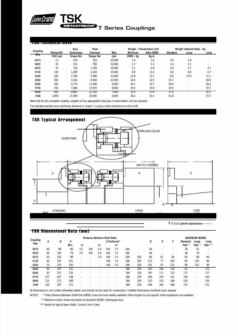
ANTI-FLY FEATURE
OVERLOAD COLLAR
GUARD RING
‡ To Suit Specific Applications
T S K
TSK T Series Couplings
TSK Typical Arrangement
CouplingDistance Between Shaft Ends MAXIMUM BORES
SizeA B C C-Preferred* D E F Standard Large Long
Min. in. in. in. Hub* * Hub* * Hub* * *
0013 40 86 66 3.5 100 5.0 140 7.0 180 - 54 - - 36 51 -
0033 45 105 79 3.5 100 5.0 140 7.0 180 - 69 - - 46 70 -
0075 55 130 99 - - 5.0 140 7.0 180 250 90 62 82 65 90 65
0135 62 152 121 - - - 140 7.0 180 250 112 77 104 80 102 80
0230 70 179 130 - - - 140 7.0 180 250 131 91 123 90 121 90
0350 90 197 131 - - - - - 180 250 163 106 116 115 - 115
0500 95 222 133 - - - - - 180 250 181 121 132 127 - 127
0740 107 247 138 - - - - - 180 250 206 135 151 140 - 140
0930 115 272 148 - - - - - 180 250 223 153 166 155 - 155
1400 130 297 171 - - - - - 180 250 248 183 180 172 - 172
All dimensions in mm unless otherwise stated, and should not be used for construction. Certified dimensions furnished upon request.
NOTES: * These Distance Between Shaft End (DBSE) sizes are more readily available. Other lengths to suit specific shaft separations are available.
** Maximum bores shown are based on standard ISO/BS rectangular keys.
*** Based on typical taper shafts. Consult J ohn Crane.
TSK Dimensional Data (mm)
CouplingMax. Peak Weight - Transmission Unit Weight Unbored Hubs - Kg
SizeRating kW/ Continuous Overload Max. Minimum Extra DBSE Standard Large Long
1000 rpm Torque Nm Torque Nm rpm DBSE - Kg Kg/m
0013 13 124 310 25,500 1.4 3.2 0.9 1.8 -
0033 33 315 790 20,000 2.7 5.3 1.6 3.1 -
0075 75 716 1,790 16,500 5.1 6.8 3.4 5.7 3.7
0135 135 1,289 3,220 14,400 8.9 11.0 5.6 8.8 6.7
0230 230 2,196 5,490 12,000 12.8 13.1 8.8 13.9 11.1
0350 350 3,342 8,360 10,500 16.0 12.5 15.7 - 18.8
0500 500 4,775 11,940 9,500 20.1 15.7 20.6 - 26.2
0740 740 7,066 17,670 8,000 25.4 19.8 29.4 - 37.2
0930 930 8,881 22,200 7,000 32.6 23.4 37.9 - 50.3
1400 1,400 13,369 33,400 6,000 46.2 31.4 51.8 - 72.5
Note that for the complete coupling, weights of two appropriate hubs plus a transmission unit are required.
The standard parallel bore machining tolerance is Grade 7, to give a light interference on the shaft.
TSK keyways will be cut to BS 4235 Pt.1(metric) or BS 46 Pt.1(inch).
TSK Technical Data
8/10/2019 ACOPLAMIENTOS TSK.pdf
http://slidepdf.com/reader/full/acoplamientos-tskpdf 3/4
TSK T Series Couplings
Select ion Procedure
Service Factor SF
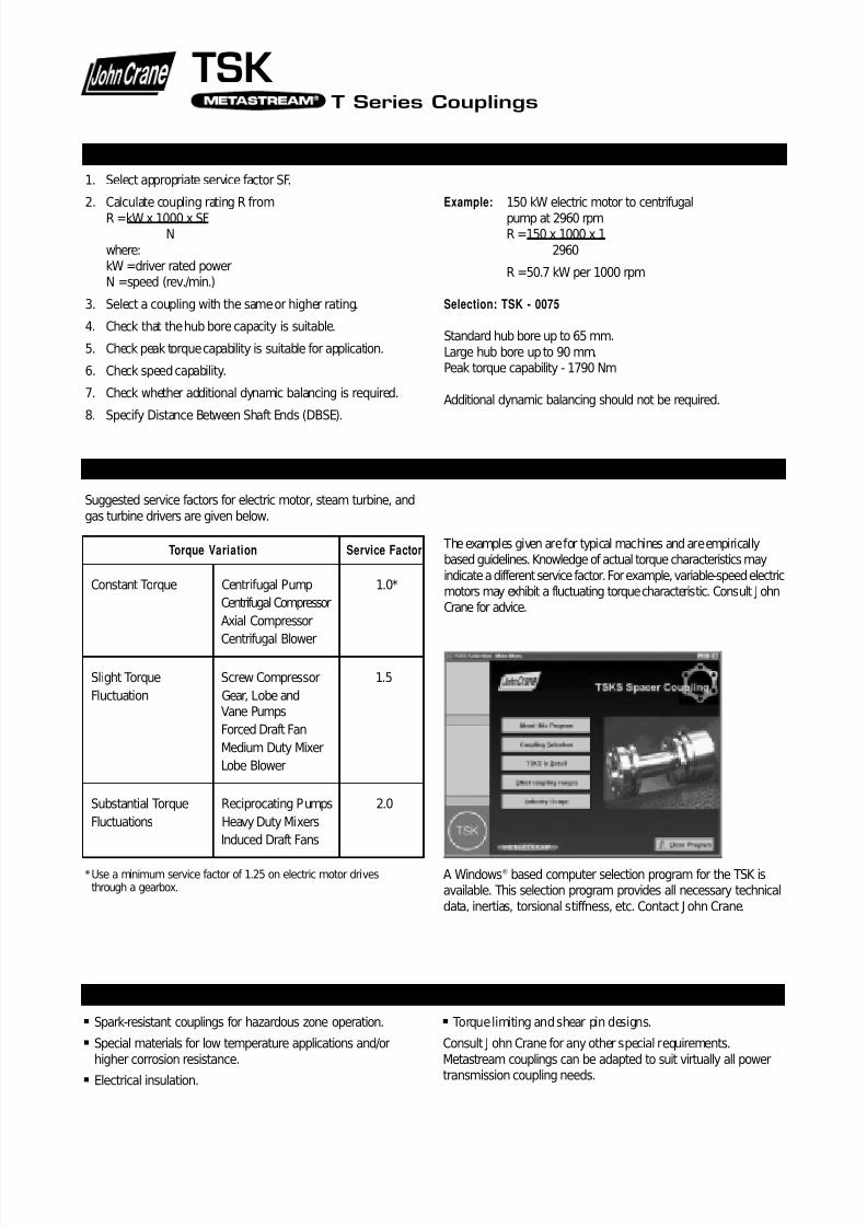
Suggested service factors for electric motor, steam turbine, and
gas turbine drivers are given below.
*Use a minimum service factor of 1.25 on electric motor drivesthrough a gearbox.
The examples given are for typical machines and are empiricallybased guidelines. Knowledge of actual torque characteristics may
indicate a different service factor. For example, variable-speed electricmotors may exhibit a fluctuating torque characteristic. Consult J ohnCrane for advice.
1. Select appropriate service factor SF.
2. Calculate coupling rating R from
R =kW x 1000 x SFN
where:kW =driver rated powerN =speed (rev./min.)
3. Select a coupling with the same or higher rating.
4. Check that the hub bore capacity is suitable.
5. Check peak torque capability is suitable for application.
6. Check speed capability.
7. Check whether additional dynamic balancing is required.
8. Specify Distance Between Shaft Ends (DBSE).
Example: 150 kW electric motor to centrifugal
pump at 2960 rpmR =150 x 1000 x 1
2960
R =50.7 kW per 1000 rpm
Selection: TSK - 0075
Standard hub bore up to 65 mm.
Large hub bore up to 90 mm.Peak torque capability - 1790 Nm
Additional dynamic balancing should not be required.
A Windows® based computer selection program for the TSK isavailable. This selection program provides all necessary technical
data, inertias, torsional stiffness, etc. Contact J ohn Crane.
Avai lab le Opt ions
Spark-resistant couplings for hazardous zone operation.
Special materials for low temperature applications and/or
higher corrosion resistance.
Electrical insulation.
Torque limiting and shear pin designs.
Consult J ohn Crane for any other special requirements.
Metastream couplings can be adapted to suit virtually all power
transmission coupling needs.
Torque Variation Service Factor
Constant Torque Centrifugal Pump 1.0*
Centrifugal Compressor
Axial Compressor
Centrifugal Blower
Slight Torque Screw Compressor 1.5
Fluctuation Gear, Lobe andVane Pumps
Forced Draft Fan
Medium Duty Mixer
Lobe Blower
Substantial Torque Reciprocating Pumps 2.0
Fluctuations Heavy Duty Mixers
Induced Draft Fans
8/10/2019 ACOPLAMIENTOS TSK.pdf
http://slidepdf.com/reader/full/acoplamientos-tskpdf 4/4
North and Latin Americas
Morton Grove, Illinois USA
Tel: 1-84 7-967-2400
Fax: 1-847-967-3915
1-800-SEALING
Europe, Middle East, Africa
Slough, UK
Tel: 44-1753-224000
Fax: 44-1753-224224
Asia Pacific
Singapore
Tel: 65-222-9161
Fax: 65-223-5035
For your nearest J ohn Crane fac ility, please co ntact o ne of the locations ab ove.
If the products featured will be used in a potentially da ngerous and /or haza rdous process, your John Crane representative should be consulted prior to their selection and use. In theinterest of co ntinuous development, J ohn Crane Compa nies reserve the right to alter designs a nd s pecifica tions without prior notice.
© 1999 J ohn Crane Print 11/99 www.johncrane.com IS O C ertified S -TSK
John Crane
TSK T Series Couplings
Coupl ing Al ignment
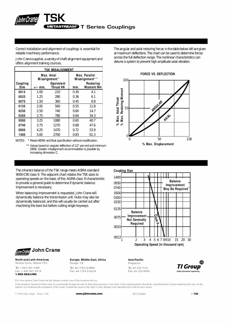
The inherent balance of the TSK range meets AGMA standard9000-C90 class 9. The adjacent chart relates the TSK sizes tooperating speeds on the basis of this AGMA class 9 characteristicto provide a general guide to determine if dynamic balance
improvement is necessary.
When balancing improvement is requested, J ohn Crane willdynamically balance the transmission unit. Hubs may also be
dynamically balanced, and this will usually be carried out aftermachining the bore but before cutting single keyways.
Correct installation and alignment of couplings is essential for
reliable machinery performance.
J ohn Crane supplies a variety of shaft alignment equipment andoffers alignment training courses.
NOTES: * Meets NEMA end float specification without modification.
** Values based on angular deflection of 1/2o per end and minimumDBSE. Greater misalignment accommodation is possible byincreasing dimension C.
The angular and axial restoring forces in the table below left are given
at maximum deflections. The chart can be used to determine forces
across the full deflection range. The nonlinear characteristics candetune a system to prevent high amplitude axial vibration.
Operating Speed (in thousand rpm)
Coupling Size
C l a s s 9
1 3 5 7 159 302 4 6 108 20
BalanceImprovementNot Generally
Required
BalanceImprovement
M ay Be Required
1400
0930
0740
0350
0230
0135
0075
0033
0013
0500
TSK MISALIGNMENT
M ax. Axial M ax. ParallelM isalignment * M isalignment * *
Coupling Equivalent RestoringSize +/– mm. Thrust kN mm. M oment Nm
0013 1.00 210 0.30 4.1
0033 1.25 280 0.36 6.1
0075 1.50 360 0.45 8.8
0135 2.00 560 0.55 11.8
0230 2.50 740 0.60 14.7
0350 2.75 780 0.64 34.3
0500 3.25 1080 0.65 40.7
0740 3.75 1270 0.68 47.6
0930 4.25 1470 0.72 53.9
1400 5.00 2700 0.83 61.3
% Max. Displacement
% M
a x . A
x i a l T h r u s t
% M
a x . R
e s t o r i n g M o m e n t
100
50 A N
G U L A
R
A X I A L
100500
0
FORCE VS. DEFLECTION
Balance Recommendat ions