Embed Size (px)
Citation preview
Centro de Investigacion Cientıfica y de EducacionSuperior de Ensenada, Baja California
MR
Programa de Posgrado en Ciencias
en Electronica y Telecomunicaciones
Performance analysis of a fourth generation wireless
communication system developed on a software defined radio
environment.
Tesis
para cubrir parcialmente los requisitos necesarios para obtener el grado de
Doctor en Ciencias
Presenta:
Vıktor Ivan Rodrıguez Abdala
Ensenada, Baja California, Mexico
2016
Tesis defendida por
Vıktor Ivan Rodrıguez Abdala
y aprobada por el Comite
Dr. Jaime Sanchez GarcıaDirector del Comite
PhD. Hamid Jafarkhani
Dr. Jorge Flores Troncoso
Dr. Miguel Angel Alonso Arevalo
Dr. J. Apolinar Reynoso Hernandez
Dr. Miguel Angel Alonso Arevalo
Coordinador del Programa de Posgrado en Electronica y Telecomunicaciones
Dra. Rufina Hernandez MartınezDirector de Estudios de Posgrado
Vıktor Ivan Rodrıguez Abdala c© 2016Queda prohibida la reproduccion parcial o total de esta obra sin el debido permiso del autor
iii
Resumen de la tesis que presenta Vıktor Ivan Rodrıguez Abdala como requisito parcialpara la obtencion del grado de Doctor en Ciencias en Electronica y Telecomunicaciones.
Analisis de desempeno en la implementacion de un sistema de comunicacioninalambrica de cuarta generacion en una plataforma de radio definido por
software.
Resumen aprobado por:
Dr. Jaime Sanchez GarcıaDirector de tesis
En los sistemas de comunicacion de 4ta y 5ta generacion se propone el uso detecnicas que aumenten la capacidad de canal al maximo, tales como el uso de multiplesantenas combinado con altos esquemas de modulacion y un gran numero de subpor-tadoras ortogonales entre si, permitiendo explotar eficientemente el espectro limitadodisponible. La dimension espacial permite aumentar la capacidad de canal, el uso demultiples antenas propicia la diversidad de informacion y el uso de receptores sencillospara la estimacion de sımbolo. En cambio, las tecnicas de multicanalizacion permitentransmitir a altas tasas de transmision con receptores mas complejos en la estimacion delsımbolo.
El incremento de dispositivos conectados a la red celular y el aumento de aplicacionesque requieren un ancho de banda mayor han provocado un cambio en la forma como seestructura la red celular. Tendencias como densificacion de red, comunicacion dispositivoa dispositivo y la presencia masiva de antenas obligan a usar arreglos virtuales para podergozar de estas tecnologıas. El uso de protocolos cooperativos permite la virtualizacionde arreglos de antenas y la comunicacion con dispositivos que se encuentren en el lımitede la cobertura de la celula, con ayuda de nodos repetidores fijos o moviles.
En esta tesis se desarrollaron las simulaciones para la implementacion de la cod-ificacion de Alamouti en la segunda fase de los protocolos cooperativos dividiendo elcodigo de diversidad espacial en cada nodo relay; ademas se desarollo una tecnica deestimacion de sımbolo para multicanalizacion debido a los cambios de dominio tiempo-frecuencia-tiempo al momento de agregar Direct Fourier Transform Spread (DFTS) en unreceptor DFTS - Orthogonal Frequency Division Multiplexing (OFDM).
En las plataformas de radio definido por software (SDR) se desarrollo un sistema decomunicacion basado en DFTS-OFDM punto-a-punto, ası como la implementacion deuna estimacion ciega de SNR para OFDM en el receptor el cual se uso para el calculo delas curvas de desempeno. Finalmente, se implementaron los nodos relay para AF, DF yEF de dos saltos en un arreglo de tres plataformas de SDR.
Palabras Clave: SDR, DFTS-OFDM, USRP, Protocolos cooperativos.
iv
Abstract of the thesis presented by Vıktor Ivan Rodrıguez Abdala as a partial requirementto obtain the Doctor in Sciences degree in Electronic and Telecommunications.
Performance analysis of a fourth generation wireless communication systemdeveloped on a software defined radio environment.
Abstract approved by:
Dr. Jaime Sanchez GarcıaThesis director
The 4th and 5th generation wireless communication systems propose the use of tech-niques that provide a maximum increase in the channel capacity, like the use of multipleantennas in combination with high modulation schemes and a large number of orthog-onal subcarriers allowing to efficiently exploit the limited available spectrum. Exploitingthe spatial domain allows to increase the channel capacity, the use of multiple antennaarrays allows to transmit in either the diversity . Diversity techniques allow to get low biterror rates in the channel with simple receivers for the symbol estimation. On the otherhand, multiplexing techniques allow to exploit the low noise channel condition to generateindependent data flows, but increases the complexity of the receiver.
The increase of both, the number of devices connected to the cellular networks andthe amount of applications that require wider bandwidths, have induced a change in theway the cellular network is structured. Trending topics like network densification, device-to-device communication and the massive antennas presence force to use virtual arraysto facilitate the access to these technologies. The use of cooperative protocols allows thevirtualization of antenna arrays and the communication with devices at the edge of thecell, with the support of fixed or mobile relay nodes.
In this dissertation we developed several simulations for Alamouti coding in phasetwo of cooperative protocols, dividing the space - time code in every relay node for theirimplementation; additionally, a symbol estimation technique for multiplexing due to thetime-frequency-time domain switching introduced by the addition of the Direct FourierTransform Spread (DFTS) stage in a DFTS - Orthogonal Frequency Division Multiplex-ing (DFTS-OFDM) receiver was developed.
In the software defined radio (SDR) boards, a point-to-point DFTS-OFDM wirelesscommunication system was developed, including a SNR blind estimation for OFDM at thereceiver which was used for Bit Error Rate (BER) performance estimation. Finally, the AF,DF and EF relay nodes for two hopes in a three SDR hardware array were developed.
Keywords: SDR, DFTS-OFDM, USRP, Cooperative Protocols.

v
Dedicatory
To my parents
Vıctor Manuel Rodrıguez Felix
Ana Rosa Abdala Roman
For being who they are, for showing me that in life you can
achieve what you wish to do and with no restrictions that can
stop us. For the confidence and support they showed me during
these years I was away and being there for me at any moment I
needed them.
To my uncle and aunt
Aureliano Rodrıguez Felix
Marta Reynoso
For accepting me into their family and helping me endure times
of loneliness.

vi
Acknowledgements
First of all, I thank God for allowing me to accomplish the dream of my life.
During the development of this thesis, I have had the support of many very enjoyable
and fascinating people. The ending of this study would not have been possible without
their contributions. It is a pleasure to use this opportunity to express my gratitude to all of
them.
To my advisor, Dr. Jaime Sanchez Garcıa, for the full support given through my doctoral
research, for trusting in me in a new and ambitious project and letting me help in other
thesis projects.
I also give thanks to the committee members, Dr. J. Apolinar Reynoso Hernandez, Dr.
Miguel Angel Alonso Arevalo, Dr. Jorge Flores Troncoso and PhD. Hamid Jafarkhani, who
gave me guidance, time and their valuable suggestions.
To my generation colleges 2011-2015, specially to my friends Ernesto Murillo, Alejan-
dro Cabrera, Daniel Reyes and Daniel Domınguez, for supporting me and sharing expe-
riences during our stay in Ensenada, you made my special days and I will never forget
you.
To my family in Ensenada, I felt like home under your support and care.
Thanks to CONACyT for providing me with financial means to develop and finish this
thesis.
Thanks to CICESE for giving me the opportunity to make my dream come true.
vii
ContentsPage
Abstract spanish iii
Abstract iv
Dedicatory v
Acknowledgements vi
List of figures ix
List of tables xi
1 Introduction 11.1 Fourth and fifth generation systems physical layer techniques . . . . . 11.2 Problem statement . . . . . . . . . . . . . . . . . . . . . . . . . . . . . 5
1.2.1 General objectives . . . . . . . . . . . . . . . . . . . . . . . . . 51.2.2 Particular objectives . . . . . . . . . . . . . . . . . . . . . . . . 6
1.3 Thesis outline . . . . . . . . . . . . . . . . . . . . . . . . . . . . . . . . 6
2 Software Defined Radio 82.1 Introduction . . . . . . . . . . . . . . . . . . . . . . . . . . . . . . . . . 82.2 Development of GNU Radio projects . . . . . . . . . . . . . . . . . . . 82.3 IT++ and GNU Radio. . . . . . . . . . . . . . . . . . . . . . . . . . . . 122.4 USRP and GNU Radio . . . . . . . . . . . . . . . . . . . . . . . . . . . 14
3 Direct Fourier Transform Spread - Ortoghonal Frequency Division Multi-plexing 163.1 Introduction . . . . . . . . . . . . . . . . . . . . . . . . . . . . . . . . . 163.2 OFDM transmitter . . . . . . . . . . . . . . . . . . . . . . . . . . . . . . 173.3 Medium access methods (OFDMA and SC-FDMA) . . . . . . . . . . . 183.4 Transmission structure . . . . . . . . . . . . . . . . . . . . . . . . . . . 22
3.4.1 DFT precoding . . . . . . . . . . . . . . . . . . . . . . . . . . . 22
4 MIMO: Diversity and multiplexing 244.1 Introduction . . . . . . . . . . . . . . . . . . . . . . . . . . . . . . . . . 244.2 Space-time and space-frequency block coding based transmit diversity 25
4.2.1 Alamouti block code . . . . . . . . . . . . . . . . . . . . . . . . 264.2.2 Alamouti based space-frequency block code . . . . . . . . . . 28
4.3 MIMO Multiplexing . . . . . . . . . . . . . . . . . . . . . . . . . . . . . 294.3.1 Symbol estimation at the receiver . . . . . . . . . . . . . . . . . 31
5 Cooperative Protocols 345.1 Introduction . . . . . . . . . . . . . . . . . . . . . . . . . . . . . . . . . 345.2 Amplify-and-Forward . . . . . . . . . . . . . . . . . . . . . . . . . . . . 375.3 Decode-and-Forward . . . . . . . . . . . . . . . . . . . . . . . . . . . . 395.4 Equalize-and-Forward . . . . . . . . . . . . . . . . . . . . . . . . . . . 40
6 System model 416.1 Introduction . . . . . . . . . . . . . . . . . . . . . . . . . . . . . . . . . 41
viii
Page
6.2 Space-frequency block codes over cooperative protocols . . . . . . . . 426.2.1 Amplify-and-Forward . . . . . . . . . . . . . . . . . . . . . . . . 446.2.2 Decode-and-Forward . . . . . . . . . . . . . . . . . . . . . . . 456.2.3 Equalize-and-Forward . . . . . . . . . . . . . . . . . . . . . . . 466.2.4 Symbol Estimation at the Destination . . . . . . . . . . . . . . . 47
6.3 MIMO Multiplexing . . . . . . . . . . . . . . . . . . . . . . . . . . . . . 506.3.1 Amplify and forward . . . . . . . . . . . . . . . . . . . . . . . . 516.3.2 Decode and forward . . . . . . . . . . . . . . . . . . . . . . . . 536.3.3 Equalize and forward . . . . . . . . . . . . . . . . . . . . . . . . 546.3.4 Symbol Estimation at the receiver . . . . . . . . . . . . . . . . 54
7 System Development 577.1 Simulation Setup . . . . . . . . . . . . . . . . . . . . . . . . . . . . . . 57
7.1.1 PHY layer Setup . . . . . . . . . . . . . . . . . . . . . . . . . . 577.2 Emulation setup . . . . . . . . . . . . . . . . . . . . . . . . . . . . . . . 59
7.2.1 Relay emulation setup . . . . . . . . . . . . . . . . . . . . . . . 64
8 Numerical results 678.1 SFBC with relay protocols simulation . . . . . . . . . . . . . . . . . . . 678.2 MIMO multiplexing simulation . . . . . . . . . . . . . . . . . . . . . . . 698.3 DFTS-OFDM emulation . . . . . . . . . . . . . . . . . . . . . . . . . . 708.4 Relay protocol emulation . . . . . . . . . . . . . . . . . . . . . . . . . . 73
9 Conclusions 759.1 Introduction . . . . . . . . . . . . . . . . . . . . . . . . . . . . . . . . . 759.2 SFBC with cooperative protocols . . . . . . . . . . . . . . . . . . . . . 769.3 MIMO with cooperative protocols . . . . . . . . . . . . . . . . . . . . . 779.4 DFTS-OFDM . . . . . . . . . . . . . . . . . . . . . . . . . . . . . . . . 789.5 DFTS-OFDM relay . . . . . . . . . . . . . . . . . . . . . . . . . . . . . 789.6 Further work . . . . . . . . . . . . . . . . . . . . . . . . . . . . . . . . . 79
List of bibliographical references 81
A GNU Radio projects 88A.1 Cooperative protocols in GNU Radio . . . . . . . . . . . . . . . . . . . 88
ix
List of figuresFigure Page
1 Interaction among C++ and Python with GNU Radio. . . . . . . . . . . . . . 9
2 Digital Modulator with GNU Radio. . . . . . . . . . . . . . . . . . . . . . . . 9
3 Convolutional encoder with GNU Radio and IT++. . . . . . . . . . . . . . . 14
4 OFDMA vs SC-FDMA. . . . . . . . . . . . . . . . . . . . . . . . . . . . . . . 19
5 Block diagram of an OFDMA-SCFDMA system. . . . . . . . . . . . . . . . . 20
6 LFDMA vs DFDMA. . . . . . . . . . . . . . . . . . . . . . . . . . . . . . . . 21
7 Equivalence of SC-FDMA and DFTS IFDMA in the uplink. . . . . . . . . . . 21
8 MIMO configurations. . . . . . . . . . . . . . . . . . . . . . . . . . . . . . . 24
9 Alamouti encoder. . . . . . . . . . . . . . . . . . . . . . . . . . . . . . . . . 26
10 Diversity at time and frequency. . . . . . . . . . . . . . . . . . . . . . . . . . 27
11 Successive interference cancellation for two spatial streams. . . . . . . . . 32
12 Network densification. . . . . . . . . . . . . . . . . . . . . . . . . . . . . . . 34
13 Relay network. . . . . . . . . . . . . . . . . . . . . . . . . . . . . . . . . . . 35
14 Relay network scenarios. . . . . . . . . . . . . . . . . . . . . . . . . . . . . 37
15 Relay network scenario proposed. . . . . . . . . . . . . . . . . . . . . . . . 41
16 DFTS-OFDM transmitter with diversity. . . . . . . . . . . . . . . . . . . . . . 42
17 Network scenario for SFBC. . . . . . . . . . . . . . . . . . . . . . . . . . . . 43
18 Relay node in amplify-and-forward. . . . . . . . . . . . . . . . . . . . . . . . 45
19 Relay node in decode-and-forward. . . . . . . . . . . . . . . . . . . . . . . . 45
20 Relay node in equalize-and-forward. . . . . . . . . . . . . . . . . . . . . . . 46
21 The receiver according to the cooperative protocol. . . . . . . . . . . . . . . 47
22 DFTS-OFDM transmitter with multiplexing. . . . . . . . . . . . . . . . . . . . 50
23 Relay network scenarios for multiplexing. . . . . . . . . . . . . . . . . . . . 52
24 Relay node in amplify-and-forward with one antenna. . . . . . . . . . . . . . 52
25 Relay node in amplify-and-forward with antenna selection. . . . . . . . . . . 53
26 Relay node in decode-and-forward with antenna selection. . . . . . . . . . . 53
27 Relay node in equalize-and-forward with antenna selection. . . . . . . . . . 54
28 Illustration of SIC signal detection for two spatial streams with DFTS. . . . . 54
29 BER Alamouti relay protocol. . . . . . . . . . . . . . . . . . . . . . . . . . . 58
30 MIMO multiplexing symbol detection comparison. . . . . . . . . . . . . . . . 59
x
Figure Page
31 GNU Radio project. . . . . . . . . . . . . . . . . . . . . . . . . . . . . . . . 60
32 Header and payload generation at the transmitter. . . . . . . . . . . . . . . 61
33 DFTS stage in OFDM transmitter. . . . . . . . . . . . . . . . . . . . . . . . . 61
34 Header and payload at the transmitter. . . . . . . . . . . . . . . . . . . . . . 62
35 OFDM stage at the transmitter. . . . . . . . . . . . . . . . . . . . . . . . . . 62
36 OFDM symbol presence detection stage. . . . . . . . . . . . . . . . . . . . 63
37 Header estimation at the receiver. . . . . . . . . . . . . . . . . . . . . . . . 63
38 Payload estimation at the receiver. . . . . . . . . . . . . . . . . . . . . . . . 63
39 AF node. . . . . . . . . . . . . . . . . . . . . . . . . . . . . . . . . . . . . . 64
40 DF node. . . . . . . . . . . . . . . . . . . . . . . . . . . . . . . . . . . . . . 65
41 EF node. . . . . . . . . . . . . . . . . . . . . . . . . . . . . . . . . . . . . . 66
42 SISO simulation results. . . . . . . . . . . . . . . . . . . . . . . . . . . . . . 67
43 SFBC simulation results. . . . . . . . . . . . . . . . . . . . . . . . . . . . . . 68
44 Cooperative protocols with DFT 192. . . . . . . . . . . . . . . . . . . . . . . 70
45 Cooperative protocols with DFT 192 and fixed SNR at phase two. . . . . . . 71
46 Received symbol and spectra. . . . . . . . . . . . . . . . . . . . . . . . . . 72
47 Emulation results. . . . . . . . . . . . . . . . . . . . . . . . . . . . . . . . . 72
48 AF node emulation. . . . . . . . . . . . . . . . . . . . . . . . . . . . . . . . 73
49 DF node emulation. . . . . . . . . . . . . . . . . . . . . . . . . . . . . . . . 74
50 EF node emulation. . . . . . . . . . . . . . . . . . . . . . . . . . . . . . . . 74
A.1 AF protocol implementation in GNU Radio. . . . . . . . . . . . . . . . . . . 88
A.2 DF protocol implementation in GNU Radio. . . . . . . . . . . . . . . . . . . 89
A.3 EF protocol implementation in GNU Radio. . . . . . . . . . . . . . . . . . . 90
xi
List of tablesTable Page
1 Alamouti space-time block code. . . . . . . . . . . . . . . . . . . . . . 27
2 Two antennas diversity scheme. . . . . . . . . . . . . . . . . . . . . . 28
3 Four antennas diversity scheme. . . . . . . . . . . . . . . . . . . . . . 28
4 Codebook for transmission over one and two antenna ports . . . . . 30
5 Two antennas S-F diversity scheme. . . . . . . . . . . . . . . . . . . . 42
6 Two relay nodes S-F diversity scheme. . . . . . . . . . . . . . . . . . 43
7 Codebook for transmission over one and two antenna ports . . . . . 51
1
1. Introduction
1.1 Fourth and fifth generation systems physical layer techniques
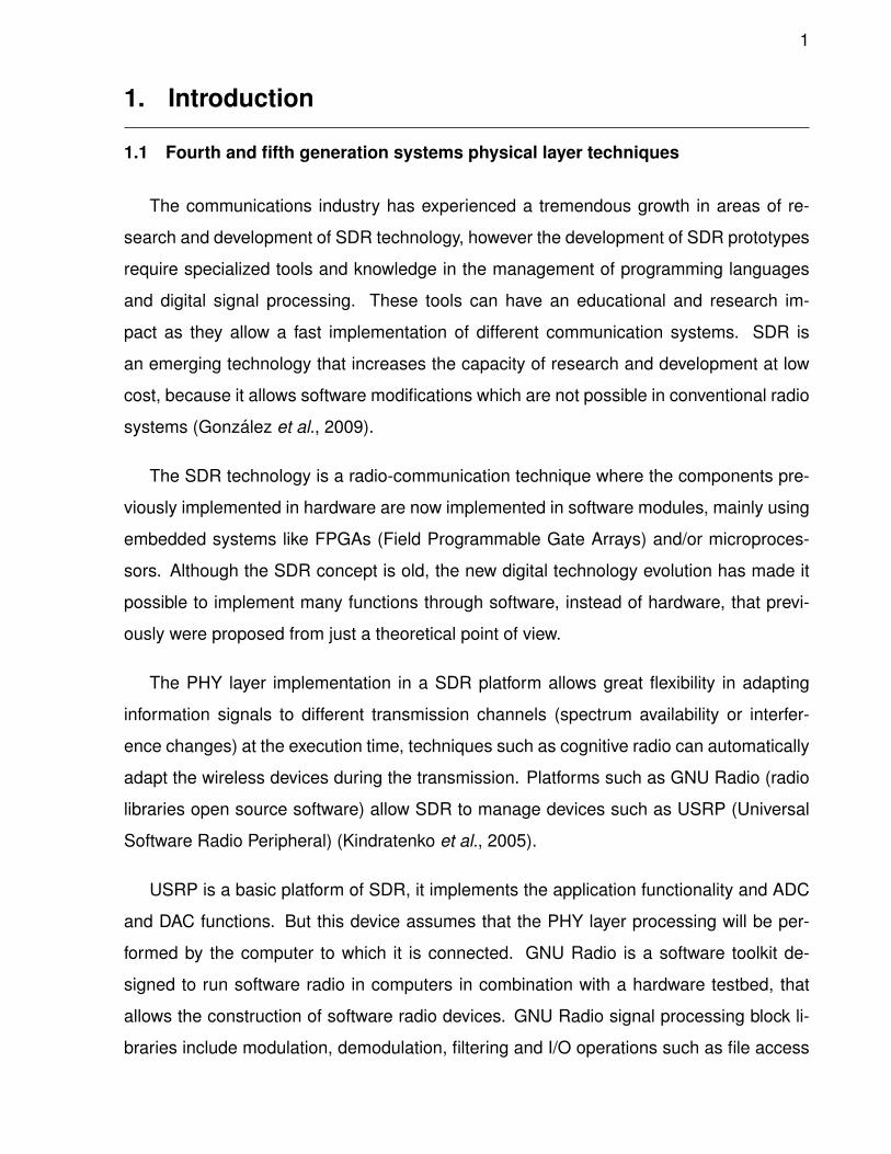
The communications industry has experienced a tremendous growth in areas of re-
search and development of SDR technology, however the development of SDR prototypes
require specialized tools and knowledge in the management of programming languages
and digital signal processing. These tools can have an educational and research im-
pact as they allow a fast implementation of different communication systems. SDR is
an emerging technology that increases the capacity of research and development at low
cost, because it allows software modifications which are not possible in conventional radio
systems (Gonzalez et al., 2009).
The SDR technology is a radio-communication technique where the components pre-
viously implemented in hardware are now implemented in software modules, mainly using
embedded systems like FPGAs (Field Programmable Gate Arrays) and/or microproces-
sors. Although the SDR concept is old, the new digital technology evolution has made it
possible to implement many functions through software, instead of hardware, that previ-
ously were proposed from just a theoretical point of view.
The PHY layer implementation in a SDR platform allows great flexibility in adapting
information signals to different transmission channels (spectrum availability or interfer-
ence changes) at the execution time, techniques such as cognitive radio can automatically
adapt the wireless devices during the transmission. Platforms such as GNU Radio (radio
libraries open source software) allow SDR to manage devices such as USRP (Universal
Software Radio Peripheral) (Kindratenko et al., 2005).
USRP is a basic platform of SDR, it implements the application functionality and ADC
and DAC functions. But this device assumes that the PHY layer processing will be per-
formed by the computer to which it is connected. GNU Radio is a software toolkit de-
signed to run software radio in computers in combination with a hardware testbed, that
allows the construction of software radio devices. GNU Radio signal processing block li-
braries include modulation, demodulation, filtering and I/O operations such as file access
2
to its transmission data. It also offers communication blocks for USRP devices, and allows
clear and simple manipulation of these devices (Dhar et al., 2006).
The fourth generation concept includes high performance radio techniques like MIMO
(Multiple Input Multiple Output) and OFDM (Orthogonal Frequency Division Multiplex-
ing), two terms that define the 3G evolution. The ITU (International Telecommunication
Union) requirements and 4G standards specify the following characteristics: for the ra-
dio channel access to abandon CDMA (Code Division Multiple Access) UMTS (Universal
Mobile Telecommunications System) access technique and adopt OFDMA (Orthogonal
Frequency Division Multiple Access) and SC-FDMA (Single Carrier - Frequency Division
Multiple Access), which is a traditional OFDM transmitter with a DFT (Direct Fourier Trans-
form) spread; To implement SDR (Software Defined Radio) looking for the optimization of
the PHY layer stages; To have an all IP (Internet Protocol) network; Maximum peak rate
up to 100 Mbps in downlink and 50 Mbps in uplink (with a bandwidth of 20 MHz in both
links and 40MHz in some configurations) (Wu et al., 2011).
The fifth generation involves a new concept in network design, mainly due to a mas-
sive increase in traffic volume and a huge growth in connected devices with several re-
quirements for a wide range of applications like video calls, VoIP (Voice over IP), cloud
storage and synchronization with other devices; as a consequence, more bandwidth and
frequency range is required. Its proposal covers massive MIMO, device-to-device (D2D)
communication and network densification, that implies a new way to use the spectrum and
acquire new frequency ranges (Saravanan and Ravi, 2011).
The 4th and 5th generations of wireless communications have in common the high
transmission rates and increased capacity on their mobile devices. Among the key im-
provements is the solution through multiple antennas enabling spatial multiplexing with up
to 8 transmit and 8 receive antennas, so in the case of LTE, CoMP (Coordinated Multipoint)
is added in the transmission and reception of signals to/from users which are located in
multiple cells (Parikh and Basu, 2011).
The main focus of the wireless technology has been geared towards the delivery of rich
multimedia content, transmitted over links with high spectral efficiency, low latency and
3
proper QoS (Quality of Service). Among the changes compared to previous generations,
it is the OFDM air interface, which allows techniques such as MIMO to be efficient and
provide high gain independent data streams. Another change was the implementation of
SC-FDMA in the uplink, this allows a scheduled orthogonal system (multiple users using a
portion of the available subcarriers) with low PAPR (Peak to Average Power Ratio) based
on DFTS-OFDM transmitters (Nagaraj et al., 2009).
MIMO specifically refers to the way the radio waves are handled in the transmission and
reception stages through multiple antennas. In traditional wireless transmission systems,
the signal is affected by the channel because of the multipath propagation, which causes
phase changes and thus data errors. MIMO exploits the multipath propagation phe-
nomenon to increase the transmission rate and reduce the error rate, so it increases the
spectral efficiency of a wireless system through the use of the spatial domain. MIMO tech-
nology has been used in wireless communications systems, like 802.11n and 802.16m,
achieving a significant increase in the rate of information transmission through different
channels via spatial multiplexing (Kadhim and Ismail, 2011).
Space Frequency (S-F) coding is a wireless communications technique for achieving
maximum diversity gain when transmitting through an antenna array. The transmitted
waves suffer from fading in the wireless channel, and since each copy follows a different
path, some copies will be more damaged than others. It is possible to use the redundancy
to more accurately estimate the transmitted signal. S-F codes combine all copies of the
received signal in a way that it is possible to extract as much information from each of
them, even though the received signal is a sum of all signals transmitted in each of the
antennas.
Modulation schemes of higher degree in combination with an array of antennas allow
transmission rates to increase significantly. Communication between a node and a mobile
device may have delays in transmission, but the use of two or more nodes for simultane-
ous data transmissions would reduce these delays and greatly increase the transmission
capacity with virtual antenna arrays. A cooperative communication system based on the
use of STNC codes (Space-Time Network Codes) was proposed to achieve time and fre-
quency synchronization with each node. For a network of N client nodes, R relay nodes
4
and a base node, the STNC offers a diversity of order (R+1) for each transmitted symbol
with (N+R) time slots, resulting in a reduction of 2N time slots compared to a traditional co-
operative systems which has N(R+1) time slots. STNC codes also allow the client nodes
to act as relay nodes for other customers to increase the transmission performance (Lai
and Liu, 2011).
Although the cooperative communications capacity has been studied for decades (Cover
and Gamal, 1979), 4G and 5G wireless networks take advantage of the presence of relay
nodes to extend the capacity of cellular networks, at the cost of increasing the system com-
plexity and the signalling overhead required for supporting device cooperation; however,
the costs related with site acquisition and backhaul are lower than those of a base station
(Hoymann et al., 2012). The presence of relay networks concept allows, inside a cell,
to coordinate among distributed antennas and achieve a macro diversity gain similar to
MIMO diversity gain through a technology called cooperative, distributed or virtual MIMO,
where the antenna array is conformed by several relays or mobiles in the cell (Sendonaris
et al., 2003; Wang et al., 2010; Zhang et al., 2015).
The use of relay stations to implement pico-cells allows the densification-over-space
concept inside a cell, with the advantage of low power consumption. Since the macro-cell
signals will be received with higher power at the mobile, they may have preference over
the pico-cells signals, however the goal is to keep the mobile connected to the pico-cell to
achieve better quality of service (Nunes et al., 2014).
Network densification is the key mechanism for wireless evolution. It includes densifi-
cation over space and frequency. Large-scale cost-effective spatial densification is facili-
tated by self-organizing networks and inter-cell interference management. Full benefits of
network densification can be realized only if it is complemented by backhaul densification,
and advanced receivers capable of interference cancellation (Bhushan et al., 2014).
Clearly, the signal bandwidth can be increased by using additional spectrum, which
leads to a linear increase in data capacity. The data load can be decreased through cell
splitting, which involves deploying a larger number of base stations, and ensuring that user
traffic is distributed as evenly as possible among all the base stations. Spatial multiplexing
5
can be increased using a larger number of antennas at the base station and user devices
(Iosifidis et al., 2014).
Cell splitting has the favourable side-effect of reducing the path loss between a user
device and base stations, which increases both desired and interfering signal levels. As
a result, interference mitigation is paramount for link efficiency improvement in modern
cellular systems. This requires a combination of adaptive resource coordination among
transmitters and advanced signal processing at the receivers.
Network densification is a combination of spatial densification and spectral aggrega-
tion. Spatial densification is performed by increasing the number of antennas per node,
and increasing the density of base stations deployed in the given geographic area, while
ensuring nearly an uniform distribution of users among all base stations. Spectral aggre-
gation refers to using larger amounts of electromagnetic spectrum, spanning all the way
from 500 MHz into the millimetric wave bands (30–300 GHz) (Swindlehurst et al., 2014).
1.2 Problem statement
The existence of projects based on both SDR and USRP in the area of wireless com-
munications is scarce or deals with previous generation systems, such as OpenBTS (Na-
talizio et al., 2010) (which is a cellular communications SDR based on GSM technology),
Hydra (Mandke et al., 2007) (a project that emulates a communication system according
to the IEEE802.11n standard), or WimaxScanner (Alshaalan et al., 2010) (a project that
seeks to implement the IEEE802.16e PHY layer). The proposed research aims to the
implementation of a DFTS-OFDM wireless communication system and its performance
analysis; it considers the design and programming of different PHY layer stages (such as
spatial diversity codes, QAM digital modulation and OFDM modulation) using the SDR
platform. The performance will be measured in a multipath channel environment, with and
without considering a line-of-sight (LOS).
1.2.1 General objectives
To design and implement a DFTS-OFDM SDR architecture system in the USRP card
including all stages that comprise the PHY layer communication standard, to analyse its
6
performance in real environments. Then to proceed to modify their space-time coding and
the modulation scheme, implementing these changes on the SDR card; the results will be
compared with those obtained with the original version.
1.2.2 Particular objectives
To study the requirements for implementing wireless communication systems in SDR
platforms. To design software modules that emulate hardware stages of a communication
system.
To study the current wireless communication standards for developing PHY layer func-
tions with a simulation tool and then proceed to emulate these PHY functions on a SDR
platform.
To study the different types of space-time codes and space-time network codes for im-
plementation in SDR platforms and analyse their performance regarding wireless network
requirements.
The evaluation will be done in terms of bit error rate (BER) versus signal to noise ratio
(SNR).
1.3 Thesis outline
The organization of this thesis is as follows:
In Chapter 2, we provide some background material which will be used in developing
our main contributions and results contained in this thesis. We begin with a brief de-
scription of SDR and GNU Radio, where we show how several software libraries and new
software modules with original codes can be included into our project.
In Chapter 3, we briefly review the concept of DFTS-OFDM, the main difference with a
traditional OFDM transmitter and how it achieves a low PAPR. We also describe OFDMA
and SC-FDMA with the interleaved and contiguous operation modes as well as basic
configurations.
In Chapter 4, we show the most common techniques used in MIMO for both diversity
7
and multiplexing in spatial domain.
In Chapter 5, we discuss diversity techniques for cooperative protocols in wireless
communications. Also, a general overview on amplify-and-forward, decode-and-forward
and equalize-and-forward is given.
In Chapter 6, we define how the DFTS-OFDM transmitter will work in both simulation
and emulation environment, their basic requirements and settings. We also describe the
link from the source to the destination node, passing through the relay node, according
to the cooperative protocol implemented. Finally, we present a description of the mod-
ifications made to the transmitter, for both diversity and spatial multiplexing, due to the
presence of the DFTS stage.
In Chapter 7, we propose some scenarios conforming its capabilities to perform a
transmission with cooperative protocols. We discuss several considerations like channel
estimation for amplify-and-forward in spatial diversity and frequency domain equalization
for spatial multiplexing.
In Chapter 8, both performance simulation and emulation results of the proposed sce-
narios will be presented and examined.
Finally, Chapter 9 contains some concluding remarks and discussion on future re-
search on this topic.
8
2. Software Defined Radio
2.1 Introduction
Based on projects like (Zheng et al., 2008; Mandke et al., 2007), the development of
several wireless communications technologies with general purpose programmable radio
testbeds is a reality; this allows the free development and modification of software for
different PHY layer stages in a single testbed without hardware settings because these
settings will be defined by a programming line code (Reddy and Lakshmi, 2014). This
paradigm known as Software Defined Radio (SDR) allows to resolve many hardware prob-
lems at the RF stage by means of software algorithms. The SDR main advantage is that
it does not require RF laboratories or special equipment, only a computer and a SDR
test-bed to deploy a radio communication system (Mitola, 1995; Mitola III, 1993).
The open source toolkit GNU Radio (Barros et al., 2012) allows the user to access
signal processing block libraries oriented to communications, this toolkit is developed in
Python programming language, allowing to monitor the system development through an
easy control panel with the high precision and critical operations performed by libraries in
C++ programming language in a kind of data panel. In this way, C++ performs only the
mathematical operations and Python controls all the system parameters (Marwanto et al.,
2009; Tucker et al., 2009).
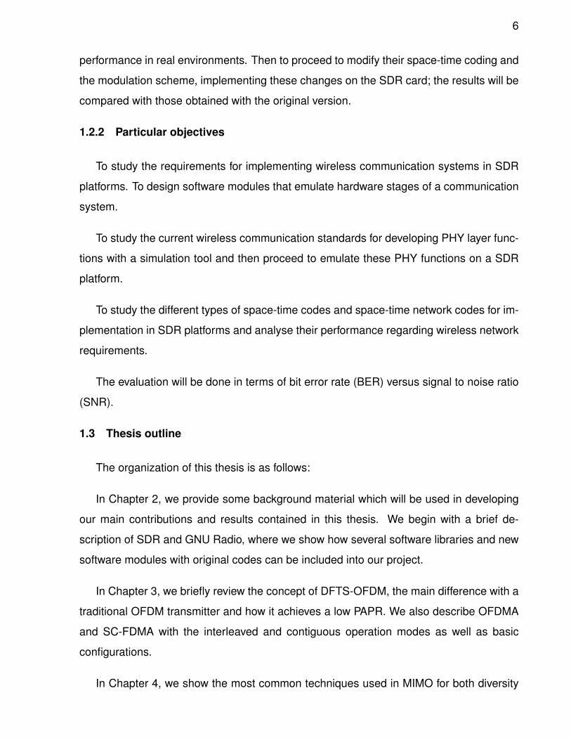
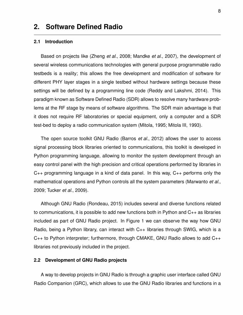
Although GNU Radio (Rondeau, 2015) includes several and diverse functions related
to communications, it is possible to add new functions both in Python and C++ as libraries
included as part of GNU Radio project. In Figure 1 we can observe the way how GNU
Radio, being a Python library, can interact with C++ libraries through SWIG, which is a
C++ to Python interpreter; furthermore, through CMAKE, GNU Radio allows to add C++
libraries not previously included in the project.
2.2 Development of GNU Radio projects
A way to develop projects in GNU Radio is through a graphic user interface called GNU
Radio Companion (GRC), which allows to use the GNU Radio libraries and functions in a
9
graphical mode. GRC facilitates the development of signal processing systems for com-
munications without having Python programming skills, since it just interprets the blocks
and translate them to a Python programming code (Beazley et al., 1996); so GRC is just
an interpreter, not a compiler.
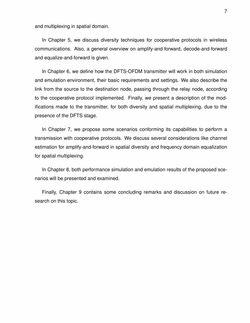
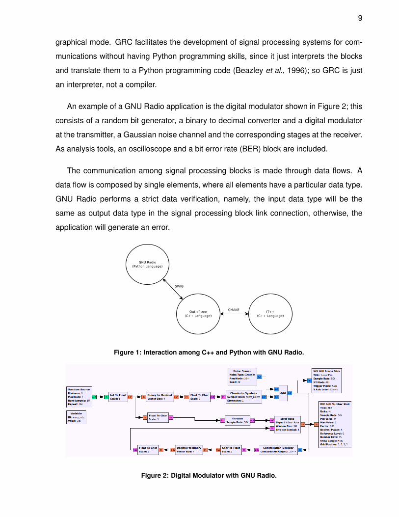
An example of a GNU Radio application is the digital modulator shown in Figure 2; this
consists of a random bit generator, a binary to decimal converter and a digital modulator
at the transmitter, a Gaussian noise channel and the corresponding stages at the receiver.
As analysis tools, an oscilloscope and a bit error rate (BER) block are included.
The communication among signal processing blocks is made through data flows. A
data flow is composed by single elements, where all elements have a particular data type.
GNU Radio performs a strict data verification, namely, the input data type will be the
same as output data type in the signal processing block link connection, otherwise, the
application will generate an error.
Figure 1: Interaction among C++ and Python with GNU Radio.
Figure 2: Digital Modulator with GNU Radio.
10
The data type may be bytes, shorts, int, floats and complex, which are selected accord-
ing to the information that will be manipulated, for an OFDM symbol and FFT samples the
type used is complex; byte type is used in channel coding because the presence of ones
and zeros in the data. Also, a data type can be byte, short, int, float or complex vector
which is different from flow type because a vector is a kind of data grouping in a deter-
mined length, the group or vector is determined by a flag inside the data flow, although for
GNU Radio, a regular data flow is just a vector whose length is the total flow.
The data type characteristics are:
1. Byte. It is conformed by a data byte, namely, 8 bits by element.
2. Short. It consists in an integer conformed by 2 bytes.
3. Int. This data type is conformed by a 4 bytes integer
4. Float. It allows a floating point through 4 bytes
5. Complex. It is an 8 bytes array, actually two float data type.
For their integration in GNU Radio, the processing blocks are conformed by 4 type files:
1. xml files. Therein are defined the block settings like data type (float, int, short or
complex), and the set of functions which it belongs to. This file is used by GRC for
the graphical representation.
2. h files. Are the libraries of the developed blocks.
3. cc files. Therein are the programming line codes that will be perfomed by the block,
the programming language is C++.
4. i files. Also known as swig files, allow the SWIG tool to obtain the parameters to the
communication among C++ block files and Python interface.
For custom blocks or block developing with new processes, GNU Radio includes a
function called gr modtool for ”out-of-tree” projects; that is a script that automatically gen-
erates all the files required to develop a new signal processing block.
11
The directory structure of an out-of-tree is:
1. apps: These contain the test and example applications.
2. cmake: These contain several setting files and they are not configurable.
3. docs: These contain the documentation files that are automatically generated by
Doxygen.
4. grc: These contain the xml files for the graphical blocks included in GRC.
5. include: These contain the h files, that are the header files of out-of-tree modules.
6. lib: These contain the cc files, that are the programming code in C++ of signal pro-
cessing blocks.
7. python: These contain Python scripts.
8. swig: These contain the i files or swig files with the interpreter settings for C++ and
Python.
All these folders, including the project root, contain ”CmakeLists.txt” with data setting
at the compiling time of signal processing blocks through CMAKE program.
gr modtool is a Python script with parameters like create or add, which through a sim-
ple interface allows the user to create, modify or delete modules and blocks of the out-
of-tree projects (Schroeder et al., 2004); also include all the folders and files required for
their development.
According to the processing requirements, GNU Radio considers several block types:
1. Sink: Only input data.
2. Source: Only output data.
3. Sync: The input data elements are the same amount that output data elements,
M=N.
12
4. Decimator: The relationship between input data and output data is M/1.
5. Interpolator: Inverse decimator block, relationship is 1/N.
6. General: The relationship between input data and output data is M/N.
7. Hiercpp: Hierarchical block conformed by a C++ blocks set.
8. Hierpython: Hierarchical block conformed by a Python blocks set.
Also, in GNU Radio there are environment variables that help the programming at the
different processes, such as:
1. noutput items. It is the element amount that the block can handle.
2. in[i]. It is the block input variable, it is an array with an i index.
3. out[i]. It is the block output variable, the data resulting from the signal processing
block is assigned to this variable.
Finally, to add an out-of-tree module to GNU Radio project, it is required some com-
mands in a Linux terminal.
$ mkdir build
$ cd build
$ cmake ../
$ make
$ sudo make install
$ sudo ldconfig
2.3 IT++ and GNU Radio.
IT++ is a C++ library with signal processing and communications classes and mathe-
matical functions. It is used mainly to help research through simulation, evaluating com-
munication systems performance in the communications area. The IT++ library kernel is
13
conformed by generic vector and matrix classes and a set of routines that allows the use
of vectors and matrices in the programming code.
IT++ library is developed by the Information Theory Department in Chalmers University
of Technology, Gothenburg, Sweden; under the terms of the GPL license (GNU General
Public License). IT++ is commonly used by communication area researchers and devel-
opers, from both industry and university. In 2005, 2006 and 2007, IT++ was developed as
part of NEWCOM (European Network of Excellence in Wireless Communications).
IT++ makes an extensive use of open source and commercial libraries to increase
functionality, speed and precision. In particular BLAS, LAPACK and FFTW libraries, also
optimized libraries for a specific platform, such as:
• ATLAS (Automatically Tuned Linear Algebra Software). Include BLAS optimized rou-
tines and a limited LAPACK set.
• IMKL (Intel Math Kernel Library). Include all BLAS, LAPACK and FFT routines
(FFTW is not required).
• ACML (AMS Core Math Library). Include BLAS, LAPACK and FFT routines (FFTW
is not required).
It is possible to compile and use IT++ without the previous libraries, but the functions
performance seems to be diminished (Boeglen, 2007); without compromising the data
integrity in the communication system simulation.
In order that GNU Radio may interact with external libraries developed for C++, they
must be included during the signal processing block developing in the out-of-tree modules.
To include external libraries a searcher module in CMAKE must be added, which will
determine the library path location and change the flags for the installation path of the
C++ library (Rodriguez and Sanchez, 2014).
According to (Rondeau, 2015), it is possible to show CMAKE the external libraries
for the integration in the project, thereby at the installation moment, CMAKE will locate
14
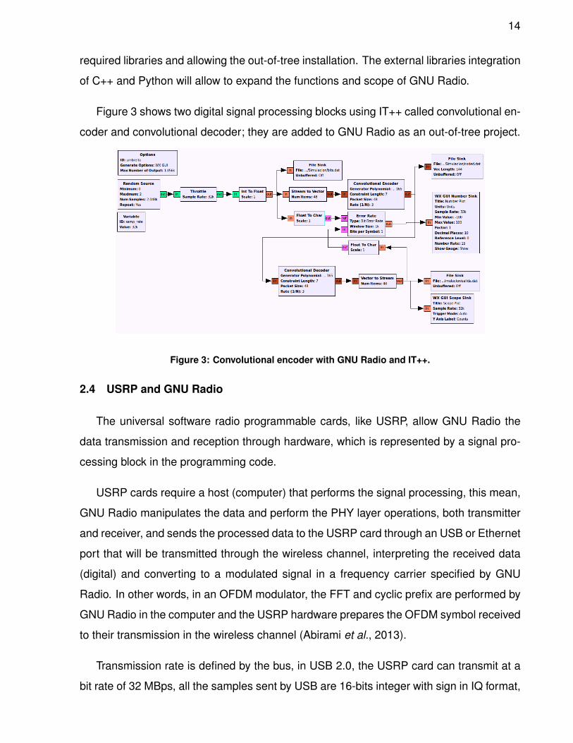
required libraries and allowing the out-of-tree installation. The external libraries integration
of C++ and Python will allow to expand the functions and scope of GNU Radio.
Figure 3 shows two digital signal processing blocks using IT++ called convolutional en-
coder and convolutional decoder; they are added to GNU Radio as an out-of-tree project.
Figure 3: Convolutional encoder with GNU Radio and IT++.
2.4 USRP and GNU Radio
The universal software radio programmable cards, like USRP, allow GNU Radio the
data transmission and reception through hardware, which is represented by a signal pro-
cessing block in the programming code.
USRP cards require a host (computer) that performs the signal processing, this mean,
GNU Radio manipulates the data and perform the PHY layer operations, both transmitter
and receiver, and sends the processed data to the USRP card through an USB or Ethernet
port that will be transmitted through the wireless channel, interpreting the received data
(digital) and converting to a modulated signal in a frequency carrier specified by GNU
Radio. In other words, in an OFDM modulator, the FFT and cyclic prefix are performed by
GNU Radio in the computer and the USRP hardware prepares the OFDM symbol received
to their transmission in the wireless channel (Abirami et al., 2013).
Transmission rate is defined by the bus, in USB 2.0, the USRP card can transmit at a
bit rate of 32 MBps, all the samples sent by USB are 16-bits integer with sign in IQ format,

15
these means, 16 bits for phase and 16 bits for quadrature, therefore data size is 4 bytes
by complex sample. This results in a data rate of 8 MMps through the USB obtained from
32 MBps / 4 Bytes. According to Nyquist criterion, the maximum effective bandwidth in
the spectrum is 8 MHz (Ettus, 2005); similar estimations can be performed for USB 3.0
and Ethernet.
16
3. Direct Fourier Transform Spread - Ortoghonal Frequency
Division Multiplexing
3.1 Introduction
One of the keys to achieve higher bit transmission rates, for next generation wire-
less networks is the implementation and use of OFDM (Orthogonal Frequency Division
Multiplexing) air interface, which is based on the use of orthogonal subcarriers for data
transmission, where every symbol is transmitted in one subcarrier, minimizing multipaths
effects in the radio channel, along with a multiple antenna transmission technique. As a
result of the reliability and versatility of the OFDM technique, it has been proposed as a
wireless access method, achieving a better performance when combined with an efficient
multiple antenna array (Capozzi et al., 2013).
OFDM is a technique that reduces the fast fading channel effects among narrow band
orthogonal subcarriers, allowing them to be handled as flat fading channels. A problem
with OFDM is that when many sub-carriers are set to zero or are not being used, the
symbol PAPR increases, which implies that conventional amplifiers need to work at the
saturation point increasing the power consumption. This is not a problem in the base
station, but, in the user device this causes a decrease in the battery life (Myung et al.,
2006b,a).
The 4th generation LTE standard for cellular networks has included a downlink access
method called OFDMA (Orthogonal Frequency Division Multiple Access), which allows
to assign different number of subcarriers to the mobile users (according to the needed
transmission rate). Furthermore, SC-FDMA (Single Carrier – Frequency Division Multiple
Access) has been proposed for the uplink. SC-FDMA allows a full orthogonal scheduled
system (multiple users using a group of available carriers) with a low PAPR (Nagaraj et al.,
2009). Both OFDMA and SC-FDMA are OFDM transmitters, the difference is the presence
of a DFT stage previous to the IFFT stage in SC-FDMA; the Single Carrier prefix in SC-
FDMA is related to the signal characteristics that are too similar to a single carrier signal
waveform, even though it is an OFDM signal (Parkvall and Astely, 2009).
17
3.2 OFDM transmitter
A traditional OFDM transmitter consists primarily of two stages: IFFT and Cyclic Prefix
(CP) addition. In the first stage, the OFDM signal is generated at baseband by taking
the IFFT of Quadrature Amplitude Modulated (QAM) or Phase-Shift Keyed (PSK) symbols
ck = ak + jbk, generating an OFDM symbol conformed by a digitally modulated symbol
mounted on each subcarrier. The CP is added to the time samples of the OFDM symbol
to avoid the Inter-Symbolic Interference (ISI); a copy of the last OFDM symbol samples,
whose length is greater than the channel impulse response, is added at the beginning of
the OFDM symbol. The frequencies of the complex exponential are fk = k/T , and the
useful part for 2N + 1 sub-carriers is given by:
u(n) =N∑
k=−N
ck exp (j2πfkt), 0 ≤ t ≤ T (1)
Previous to the OFDM stage is the digital modulator, this modulator converts the data
bit (ones and zeros) into complex values according to a symbol constellation, if the mod-
ulator is Quadrature Phase Shift Keying (QPSK), it deals with two bits per symbol. In the
case of a QAM modulator, the number of bits per symbol is log2 of the QAM constellation
size.
For a DFTS-OFDM transmitter it is necessary to add a DFT stage between the digital
modulator and the IFFT, in this way the IFFT will transform the DFTS samples and not the
modulated digital symbols (Ghosh et al., 2010). The DFT size will depend on the number
of the subcarriers needed by the source, the remaining sub-carriers (N −M) will be set
to zero by the transmitter to accomplish the IFFT size. The two ways in which the DFTS
samples can be mapped into the IFFT stage are localized or distributed, depending on the
subcarriers available at the receiver side; this is because an OFDM symbol can be shared
by multiple users. The DFTS-OFDM symbol is given by:
18
x = C F−1N D FMx (2)
where F−1N and FM are the N -point IFFT and M -point DFT matrices, respectively. D
denotes the sub-carrier mapping. C represents the CP insertion matrix (Priyanto et al.,
2007).
At the receiver side, the useful symbols for a particular terminal are obtained after the
FFT, and the equalization should be done before sending them to the IDFT stage. This
way, the equalizer must be implemented in the frequency domain over signals that can not
be related to any modulation constellation. Then, the common Decision Feedback Equal-
izer (DFE) can not be used in this case, because DFE estimates the received symbols
according to the constellation used by the digital modulator (Zhang et al., 2010; Noune
and Nix, 2009; Wang et al., 2008).
3.3 Medium access methods (OFDMA and SC-FDMA)
The OFDMA technique was originally introduced as an air interface technology in the
fixed wireless network IEEE802.16d standard in 2004; the IEEE802.16e standard was
implemented in 2005 in order to allow users mobility in wireless networks. The adoption
of the OFDMA technique on the PHY layer by 3GGP was done in 2005 as an evolution of
WCDMA (Wideband CDMA) defined by the UMTS (Universal Mobile Telecommunications
System). Such modification is included in the standard referred as 3GPP LTE Release 8,
which was finished in 2008 (Yuan et al., 2010). The 3GPP standard release 10, known
as LTE-Advanced, also includes these media access methods, while the 5th generation
foresees a combination of these two techniques and single carrier modulation, due to the
presence of millimeter wave communications (Bhushan et al., 2014).
OFDMA enables the allocation of time/frequency resources to specific users, named
logical basic resource units which consist of subbands in frequency and one or more
OFDM symbols in time domain. A subband comprises several subcarriers. The basic
resource units are then mapped to the physical OFDMA frame; there exist two permuta-
19
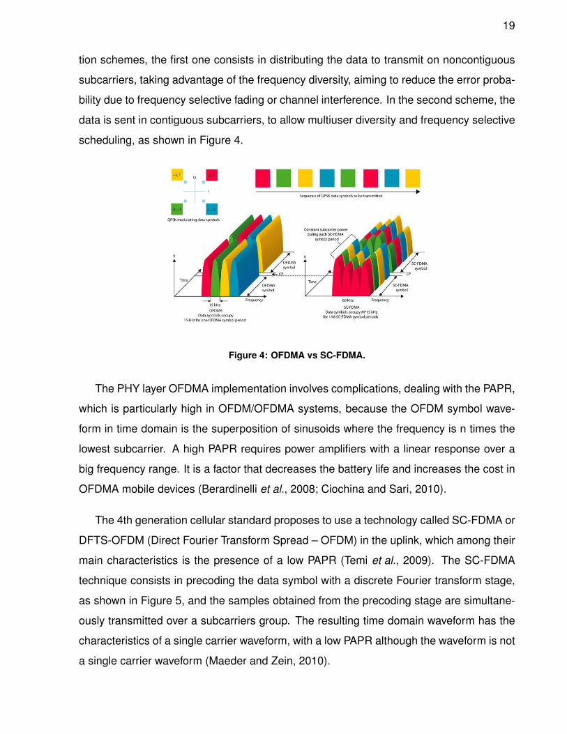
tion schemes, the first one consists in distributing the data to transmit on noncontiguous
subcarriers, taking advantage of the frequency diversity, aiming to reduce the error proba-
bility due to frequency selective fading or channel interference. In the second scheme, the
data is sent in contiguous subcarriers, to allow multiuser diversity and frequency selective
scheduling, as shown in Figure 4.
Figure 4: OFDMA vs SC-FDMA.
The PHY layer OFDMA implementation involves complications, dealing with the PAPR,
which is particularly high in OFDM/OFDMA systems, because the OFDM symbol wave-
form in time domain is the superposition of sinusoids where the frequency is n times the
lowest subcarrier. A high PAPR requires power amplifiers with a linear response over a
big frequency range. It is a factor that decreases the battery life and increases the cost in
OFDMA mobile devices (Berardinelli et al., 2008; Ciochina and Sari, 2010).
The 4th generation cellular standard proposes to use a technology called SC-FDMA or
DFTS-OFDM (Direct Fourier Transform Spread – OFDM) in the uplink, which among their
main characteristics is the presence of a low PAPR (Temi et al., 2009). The SC-FDMA
technique consists in precoding the data symbol with a discrete Fourier transform stage,
as shown in Figure 5, and the samples obtained from the precoding stage are simultane-
ously transmitted over a subcarriers group. The resulting time domain waveform has the
characteristics of a single carrier waveform, with a low PAPR although the waveform is not
a single carrier waveform (Maeder and Zein, 2010).
20
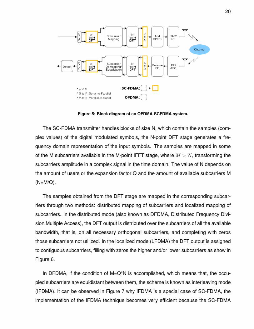
Figure 5: Block diagram of an OFDMA-SCFDMA system.
The SC-FDMA transmitter handles blocks of size N, which contain the samples (com-
plex values) of the digital modulated symbols, the N-point DFT stage generates a fre-
quency domain representation of the input symbols. The samples are mapped in some
of the M subcarriers available in the M-point IFFT stage, where M > N , transforming the
subcarriers amplitude in a complex signal in the time domain. The value of N depends on
the amount of users or the expansion factor Q and the amount of available subcarriers M
(N=M/Q).
The samples obtained from the DFT stage are mapped in the corresponding subcar-
riers through two methods: distributed mapping of subcarriers and localized mapping of
subcarriers. In the distributed mode (also known as DFDMA, Distributed Frequency Divi-
sion Multiple Access), the DFT output is distributed over the subcarriers of all the available
bandwidth, that is, on all necessary orthogonal subcarriers, and completing with zeros
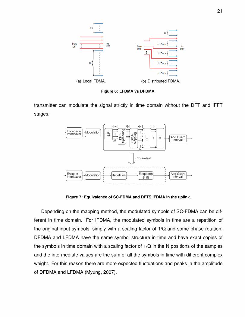
those subcarriers not utilized. In the localized mode (LFDMA) the DFT output is assigned
to contiguous subcarriers, filling with zeros the higher and/or lower subcarriers as show in
Figure 6.
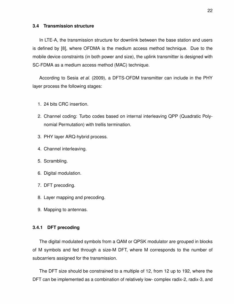
In DFDMA, if the condition of M=Q*N is accomplished, which means that, the occu-
pied subcarriers are equidistant between them, the scheme is known as interleaving mode
(IFDMA). It can be observed in Figure 7 why IFDMA is a special case of SC-FDMA, the
implementation of the IFDMA technique becomes very efficient because the SC-FDMA
21
(a) Local FDMA. (b) Distributed FDMA.
Figure 6: LFDMA vs DFDMA.
transmitter can modulate the signal strictly in time domain without the DFT and IFFT
stages.
Figure 7: Equivalence of SC-FDMA and DFTS IFDMA in the uplink.
Depending on the mapping method, the modulated symbols of SC-FDMA can be dif-
ferent in time domain. For IFDMA, the modulated symbols in time are a repetition of
the original input symbols, simply with a scaling factor of 1/Q and some phase rotation.
DFDMA and LFDMA have the same symbol structure in time and have exact copies of
the symbols in time domain with a scaling factor of 1/Q in the N positions of the samples
and the intermediate values are the sum of all the symbols in time with different complex
weight. For this reason there are more expected fluctuations and peaks in the amplitude
of DFDMA and LFDMA (Myung, 2007).
22
3.4 Transmission structure
In LTE-A, the transmission structure for downlink between the base station and users
is defined by [8], where OFDMA is the medium access method technique. Due to the
mobile device constraints (in both power and size), the uplink transmitter is designed with
SC-FDMA as a medium access method (MAC) technique.
According to Sesia et al. (2009), a DFTS-OFDM transmitter can include in the PHY
layer process the following stages:
1. 24 bits CRC insertion.
2. Channel coding: Turbo codes based on internal interleaving QPP (Quadratic Poly-
nomial Permutation) with trellis termination.
3. PHY layer ARQ-hybrid process.
4. Channel interleaving.
5. Scrambling.
6. Digital modulation.
7. DFT precoding.
8. Layer mapping and precoding.
9. Mapping to antennas.
3.4.1 DFT precoding
The digital modulated symbols from a QAM or QPSK modulator are grouped in blocks
of M symbols and fed through a size-M DFT, where M corresponds to the number of
subcarriers assigned for the transmission.
The DFT size should be constrained to a multiple of 12, from 12 up to 192, where the
DFT can be implemented as a combination of relatively low- complex radix-2, radix-3, and
23
radix-5 FFT processing. The DFT sizes of 60, 84, 120, 132, 156, 168 and 180 will not be
allowed.
It can be observed that although an OFDM symbol can be conformed by 2048 sub-
carriers, the DFT size represents only close to 10% of throughput symbol, leaving the
remaining subcarriers with a value of zero, this characteristic allows that multiple users
share an OFDM symbol.

24
4. MIMO: Diversity and multiplexing
4.1 Introduction
Due to the limitations in traditional wireless links, the research community was looking
for an alternative to design very high speed wireless links that offer good quality-of-service
and greater range capability in non-line-of-sight (NLOS) environments. The use of multiple
antennas at the transmitter and receiver increases the channel capacity gain, compared
to one-antenna links, by exploiting spatial domain.
There exist several configurations of antenna arrays according to the pattern in both
transmitter and receiver, as shown in Figure 8; if the transmitter and receiver have one
antenna it is called single input, single output (SISO); if there are multiple antennas at
the transmitter and one antenna at the receiver the configuration is called multiple input,
single output (MISO); one antenna at the transmitter and multiple antennas at the receiver
it corresponds to single input, multiple output (SIMO); finally, when there are multiple an-
tennas at both the transmitter and the receiver, the configuration is called multiple input
and multiple output (MIMO) (Yellin and Weinstein, 1994; Goldsmith et al., 2003; Akyildiz
et al., 2010).
Figure 8: MIMO configurations.
No matter what the antenna array, there is a trade-off among diversity and multiplexing,
the multiple antenna presence can help to get diversity in the transmitter (MISO), receiver
(SIMO) or both (MIMO), in this way the signal detection at the receiver will be an operation
25
with low computational complexity and a resulting low BER in low SNR channels in com-
parison with SISO; or the antenna array can be used to generate multiple flow streams
independent among them, where each stream can be modulated with different schemes,
this kind of transmission requires high SNR and low correlation channels to avoid interfer-
ence among the streams, the signal detection at the receiver is more complex and requires
all the streams to cancel the interference, because each stream produces interference to
the other streams (Li et al., 2010).
Recently the research was focused on Massive MIMO (Larsson et al., 2014; Rusek
et al., 2013), this technique consists in highly increasing the number of antennas in the
transmitter and receiver arrays, looking for the limits in the MIMO channel capacity exploit-
ing the spatial domain. The presence of massive antenna arrays increases the complexity
of signal detection at the receiver, in this way, the use of efficient algorithms to estimate
the received symbol without error is required.
4.2 Space-time and space-frequency block coding based transmit diversity
The estimation of the CSI for a frequency selective channel with many taps is a com-
plex task; several works have addressed the problem of exploiting available spatial and
frequency diversities, when neither the transmitter nor the receiver knows the CSI. In order
to achieve the time and frequency diversities several schemes were proposed in (Tarokh
et al., 1999; Tarokh and Jafarkhani, 2000; Hughes, 2000; Hochwald and Sweldens, 2000;
Tao, 2006; Borgmann and Bolcskei, 2005; Ma et al., 2005; Zhu and Jafarkhani, 2005; Him-
soon et al., 2006; Hong et al., 2006; Zhu and Jafarkhani, 2006; Li et al., 2008; Fazel and
Jafarkhani, 2008; Jafarkhani and Seshadri, 2003).
The diversity mode allows to exploit the spatial domain, decreasing the BER by sending
copies of the symbol through the channel, in this way, the receiver has several copies of the
symbol proportional to the number of antennas in both arrays. According to the orthogonal
block code, the transmission rate can be affected, but this is not a priority because it is
exploiting the diversity. This kind of block codes are suggested to be used in channels
with a low SNR, where it is required to help the receiver in the symbol estimation.
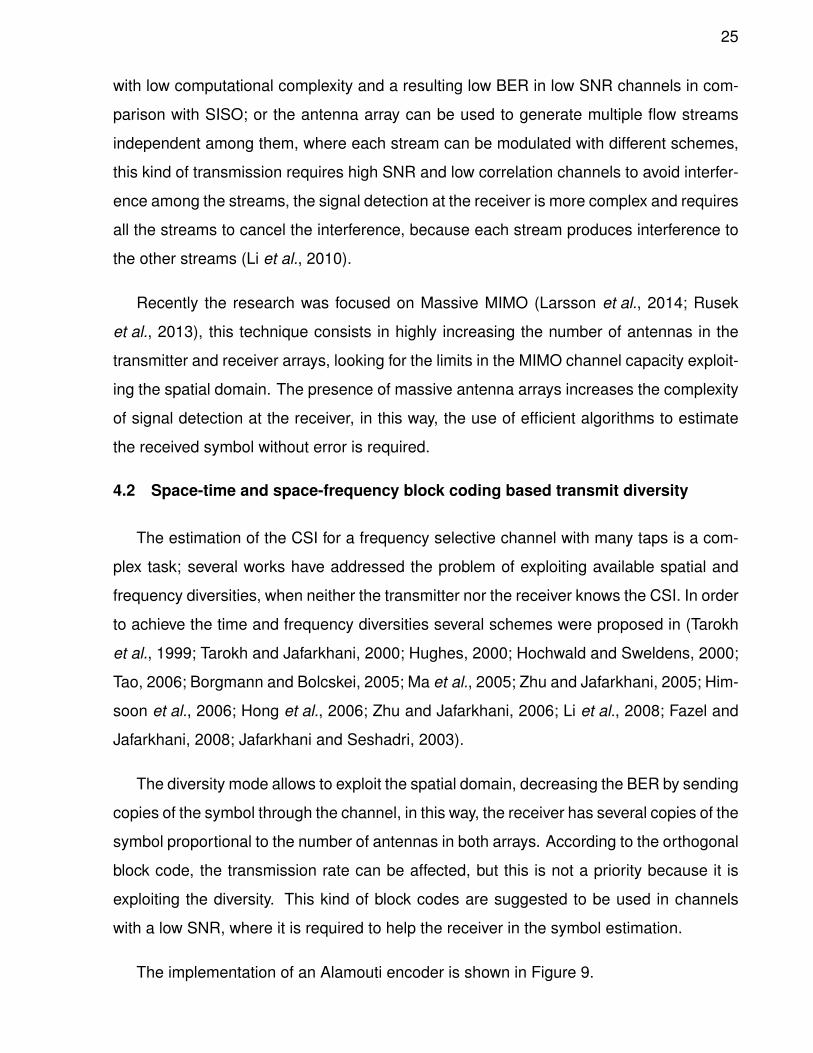
The implementation of an Alamouti encoder is shown in Figure 9.
26
Figure 9: Alamouti encoder.
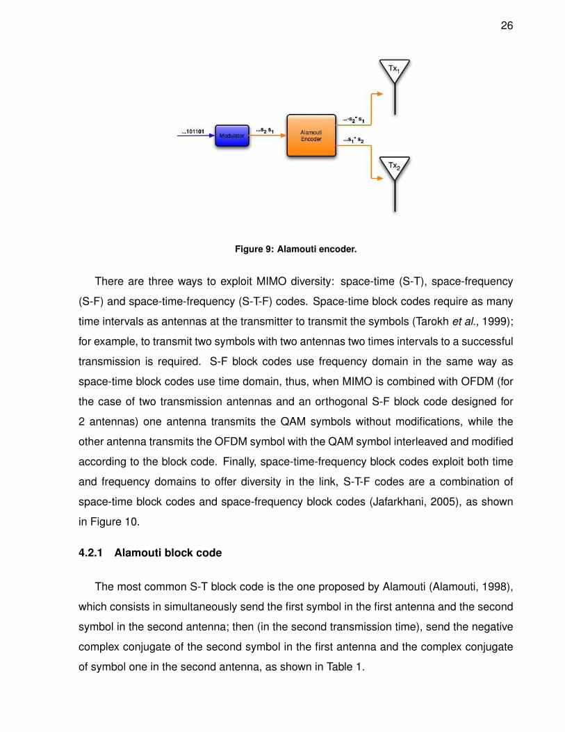
There are three ways to exploit MIMO diversity: space-time (S-T), space-frequency
(S-F) and space-time-frequency (S-T-F) codes. Space-time block codes require as many
time intervals as antennas at the transmitter to transmit the symbols (Tarokh et al., 1999);
for example, to transmit two symbols with two antennas two times intervals to a successful
transmission is required. S-F block codes use frequency domain in the same way as
space-time block codes use time domain, thus, when MIMO is combined with OFDM (for
the case of two transmission antennas and an orthogonal S-F block code designed for
2 antennas) one antenna transmits the QAM symbols without modifications, while the
other antenna transmits the OFDM symbol with the QAM symbol interleaved and modified
according to the block code. Finally, space-time-frequency block codes exploit both time
and frequency domains to offer diversity in the link, S-T-F codes are a combination of
space-time block codes and space-frequency block codes (Jafarkhani, 2005), as shown
in Figure 10.
4.2.1 Alamouti block code
The most common S-T block code is the one proposed by Alamouti (Alamouti, 1998),
which consists in simultaneously send the first symbol in the first antenna and the second
symbol in the second antenna; then (in the second transmission time), send the negative
complex conjugate of the second symbol in the first antenna and the complex conjugate
of symbol one in the second antenna, as shown in Table 1.
27
Figure 10: Diversity at time and frequency.
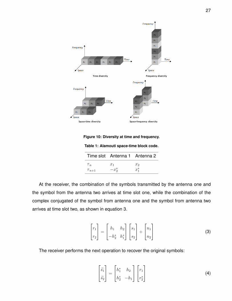
Table 1: Alamouti space-time block code.
Time slot Antenna 1 Antenna 2
τn x1 x2τn+1 −x∗2 x∗1
At the receiver, the combination of the symbols transmitted by the antenna one and
the symbol from the antenna two arrives at time slot one, while the combination of the
complex conjugated of the symbol from antenna one and the symbol from antenna two
arrives at time slot two, as shown in equation 3.
r1r2
=
h1 h2
−h∗2 h∗1
s1s2
+
n1
n2
(3)
The receiver performs the next operation to recover the original symbols:
s1s2
=
h∗1 h2
h∗2 −h1
r1r∗2
(4)
28
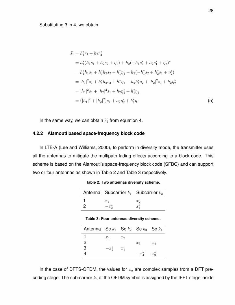
Substituting 3 in 4, we obtain:
s1 = h∗1r1 + h2r∗2
= h∗1(h1s1 + h2s2 + η1) + h2(−h1s∗2 + h2s∗1 + η2)
∗
= h∗1h1s1 + h∗1h2s2 + h∗1η1 + h2(−h∗1s2 + h∗2s1 + η∗2)
= |h1|2s1 + h∗1h2s2 + h∗1η1 − h2h∗1s2 + |h2|2s1 + h2η∗2
= |h1|2s1 + |h2|2s1 + h2η∗2 + h∗1η1
= (|h1|2 + |h2|2)s1 + h2η∗2 + h∗1η1 (5)
In the same way, we can obtain s2 from equation 4.
4.2.2 Alamouti based space-frequency block code
In LTE-A (Lee and Williams, 2000), to perform in diversity mode, the transmitter uses
all the antennas to mitigate the multipath fading effects according to a block code. This
scheme is based on the Alamouti’s space-frequency block code (SFBC) and can support
two or four antennas as shown in Table 2 and Table 3 respectively.
Table 2: Two antennas diversity scheme.
Antenna Subcarrier k1 Subcarrier k2
1 x1 x22 −x∗2 x∗1
Table 3: Four antennas diversity scheme.
Antenna Sc k1 Sc k2 Sc k3 Sc k4
1 x1 x22 x3 x43 −x∗2 x∗14 −x∗4 x∗3
In the case of DFTS-OFDM, the values for xn are complex samples from a DFT pre-
coding stage. The sub-carrier kn of the OFDM symbol is assigned by the IFFT stage inside
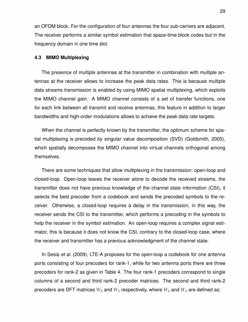
29
an OFDM block. For the configuration of four antennas the four sub-carriers are adjacent.
The receiver performs a similar symbol estimation that space-time block codes but in the
frequency domain in one time slot.
4.3 MIMO Multiplexing
The presence of multiple antennas at the transmitter in combination with multiple an-
tennas at the receiver allows to increase the peak data rates. This is because multiple
data streams transmission is enabled by using MIMO spatial multiplexing, which exploits
the MIMO channel gain. A MIMO channel consists of a set of transfer functions, one
for each link between all transmit and receive antennas, this feature in addition to larger
bandwidths and high-order modulations allows to achieve the peak data rate targets.
When the channel is perfectly known by the transmitter, the optimum scheme for spa-
tial multiplexing is precoded by singular value decomposition (SVD) (Goldsmith, 2005),
which spatially decomposes the MIMO channel into virtual channels orthogonal among
themselves.
There are some techniques that allow multiplexing in the transmission: open-loop and
closed-loop. Open-loop leaves the receiver alone to decode the received streams, the
transmitter does not have previous knowledge of the channel state information (CSI), it
selects the best precoder from a codebook and sends the precoded symbols to the re-
ceiver. Otherwise, a closed-loop requires a delay in the transmission, in this way, the
receiver sends the CSI to the transmitter, which performs a precoding in the symbols to
help the receiver in the symbol estimation. An open-loop requires a complex signal esti-
mator, this is because it does not know the CSI, contrary to the closed-loop case, where
the receiver and transmitter has a previous acknowledgment of the channel state.
In Sesia et al. (2009), LTE-A proposes for the open-loop a codebook for one antenna
ports consisting of four precoders for rank-1, while for two antenna ports there are three
precoders for rank-2 as given in Table 4. The four rank-1 precoders correspond to single
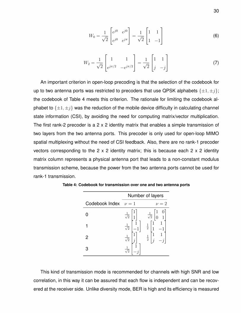
columns of a second and third rank-2 precoder matrices. The second and third rank-2
precoders are DFT matrices W0 and W2 respectively, where W0 and W2 are defined as:
30
W0 =1√2
ej0 ej0
ej0 ejπ
=1√2
1 1
1 −1
(6)
W2 =1√2
1 1
ejπ/2 −ejπ/2
=1√2
1 1
j −j
(7)
An important criterion in open-loop precoding is that the selection of the codebook for
up to two antenna ports was restricted to precoders that use QPSK alphabets {±1,±j};
the codebook of Table 4 meets this criterion. The rationale for limiting the codebook al-
phabet to {±1,±j} was the reduction of the mobile device difficulty in calculating channel
state information (CSI), by avoiding the need for computing matrix/vector multiplication.
The first rank-2 precoder is a 2 x 2 identity matrix that enables a simple transmission of
two layers from the two antenna ports. This precoder is only used for open-loop MIMO
spatial multiplexing without the need of CSI feedback. Also, there are no rank-1 precoder
vectors corresponding to the 2 x 2 identity matrix; this is because each 2 x 2 identity
matrix column represents a physical antenna port that leads to a non-constant modulus
transmission scheme, because the power from the two antenna ports cannot be used for
rank-1 transmission.
Table 4: Codebook for transmission over one and two antenna ports
Number of layers
Codebook Index ν = 1 ν = 2
0 1√2
[11
]1√2
[1 00 1
]1 1√
2
[1−1
]12
[1 11 −1
]2 1√
2
[1j
]12
[1 1j −j
]3 1√
2
[1−j
]
This kind of transmission mode is recommended for channels with high SNR and low
correlation, in this way it can be assured that each flow is independent and can be recov-
ered at the receiver side. Unlike diversity mode, BER is high and its efficiency is measured
31
with channel capacity vs SINR graphs.
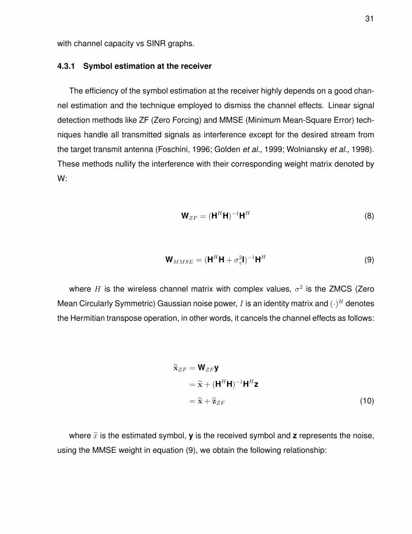
4.3.1 Symbol estimation at the receiver
The efficiency of the symbol estimation at the receiver highly depends on a good chan-
nel estimation and the technique employed to dismiss the channel effects. Linear signal
detection methods like ZF (Zero Forcing) and MMSE (Minimum Mean-Square Error) tech-
niques handle all transmitted signals as interference except for the desired stream from
the target transmit antenna (Foschini, 1996; Golden et al., 1999; Wolniansky et al., 1998).
These methods nullify the interference with their corresponding weight matrix denoted by
W:
WZF = (HHH)−1HH (8)
WMMSE = (HHH + σ2zI)−1HH (9)
where H is the wireless channel matrix with complex values, σ2 is the ZMCS (Zero
Mean Circularly Symmetric) Gaussian noise power, I is an identity matrix and (·)H denotes
the Hermitian transpose operation, in other words, it cancels the channel effects as follows:
xZF = WZFy
= x + (HHH)−1HHz
= x + zZF (10)
where x is the estimated symbol, y is the received symbol and z represents the noise,
using the MMSE weight in equation (9), we obtain the following relationship:
32
xMMSE = WMMSEy
= (HHH + σ2zI)−1HHy
= x + (HHH + σ2zI)−1HHz
= x + zMMSE (11)
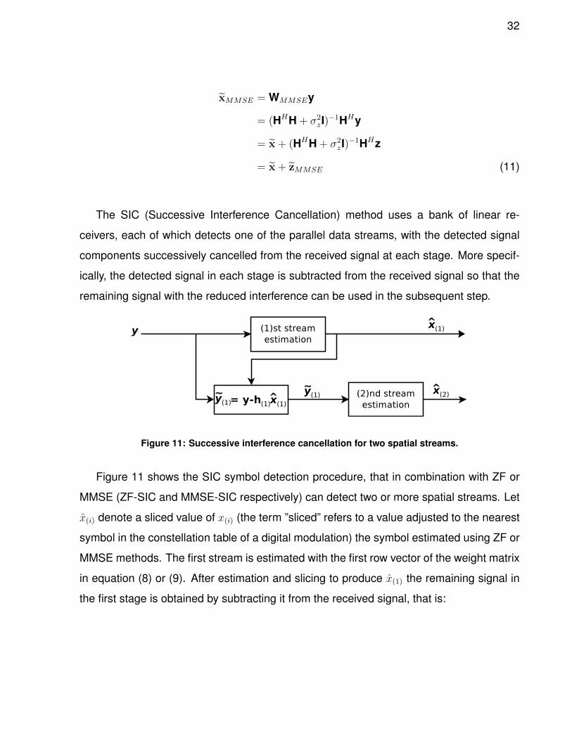
The SIC (Successive Interference Cancellation) method uses a bank of linear re-
ceivers, each of which detects one of the parallel data streams, with the detected signal
components successively cancelled from the received signal at each stage. More specif-
ically, the detected signal in each stage is subtracted from the received signal so that the
remaining signal with the reduced interference can be used in the subsequent step.
Figure 11: Successive interference cancellation for two spatial streams.
Figure 11 shows the SIC symbol detection procedure, that in combination with ZF or
MMSE (ZF-SIC and MMSE-SIC respectively) can detect two or more spatial streams. Let
x(i) denote a sliced value of x(i) (the term ”sliced” refers to a value adjusted to the nearest
symbol in the constellation table of a digital modulation) the symbol estimated using ZF or
MMSE methods. The first stream is estimated with the first row vector of the weight matrix
in equation (8) or (9). After estimation and slicing to produce x(1) the remaining signal in
the first stage is obtained by subtracting it from the received signal, that is:
33
y(1) = y− h(1)x(1)
= h(1)(x(1) − x(1)) + h(2)x(2) + z (12)
if x(1) = x(1), then the interference is successfully cancelled in the course of estimating
x(2).
34
5. Cooperative Protocols
5.1 Introduction
Although this topic has been researched many years, it is actually considered as a way
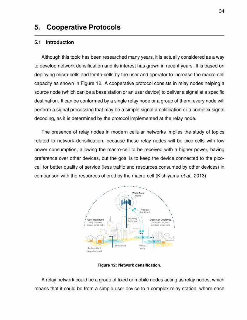
to develop network densification and its interest has grown in recent years. It is based on
deploying micro-cells and femto-cells by the user and operator to increase the macro-cell
capacity as shown in Figure 12. A cooperative protocol consists in relay nodes helping a
source node (which can be a base station or an user device) to deliver a signal at a specific
destination. It can be conformed by a single relay node or a group of them, every node will
perform a signal processing that may be a simple signal amplification or a complex signal
decoding, as it is determined by the protocol implemented at the relay node.
The presence of relay nodes in modern cellular networks implies the study of topics
related to network densification, because these relay nodes will be pico-cells with low
power consumption, allowing the macro-cell to be received with a higher power, having
preference over other devices, but the goal is to keep the device connected to the pico-
cell for better quality of service (less traffic and resources consumed by other devices) in
comparison with the resources offered by the macro-cell (Kishiyama et al., 2013).
Figure 12: Network densification.
A relay network could be a group of fixed or mobile nodes acting as relay nodes, which
means that it could be from a simple user device to a complex relay station, where each
35
relay node will be managed by the device who will transmit the information as shown in
Figure 13.
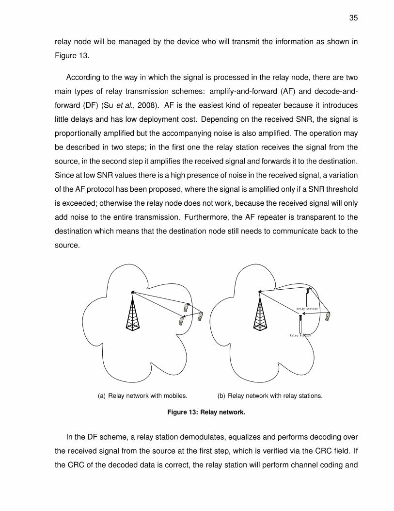
According to the way in which the signal is processed in the relay node, there are two
main types of relay transmission schemes: amplify-and-forward (AF) and decode-and-
forward (DF) (Su et al., 2008). AF is the easiest kind of repeater because it introduces
little delays and has low deployment cost. Depending on the received SNR, the signal is
proportionally amplified but the accompanying noise is also amplified. The operation may
be described in two steps; in the first one the relay station receives the signal from the
source, in the second step it amplifies the received signal and forwards it to the destination.
Since at low SNR values there is a high presence of noise in the received signal, a variation
of the AF protocol has been proposed, where the signal is amplified only if a SNR threshold
is exceeded; otherwise the relay node does not work, because the received signal will only
add noise to the entire transmission. Furthermore, the AF repeater is transparent to the
destination which means that the destination node still needs to communicate back to the
source.
(a) Relay network with mobiles. (b) Relay network with relay stations.
Figure 13: Relay network.
In the DF scheme, a relay station demodulates, equalizes and performs decoding over
the received signal from the source at the first step, which is verified via the CRC field. If
the CRC of the decoded data is correct, the relay station will perform channel coding and
36
will forward the new signal (with new CRC) to the destination at the second step. This
scheme suffers an extra delay due to the additional signal processing tasks and it is rela-
tively expensive to deploy. Therefore, a DF relay can provide independent scheduling and
link adaptation, in this way, it does not forward the interference and noise in the received
signals, but only the useful data.
Additionally, we study a scheme called equalize-and-forward (EF), where the symbol is
only equalized at the relay station and then forwarded to the destination. In this scheme,
a relay station receives the signal from the source at the first step, then removes the
channel effect of the previous step equalizing the received signal and finally forwards it to
the destination at the second step.
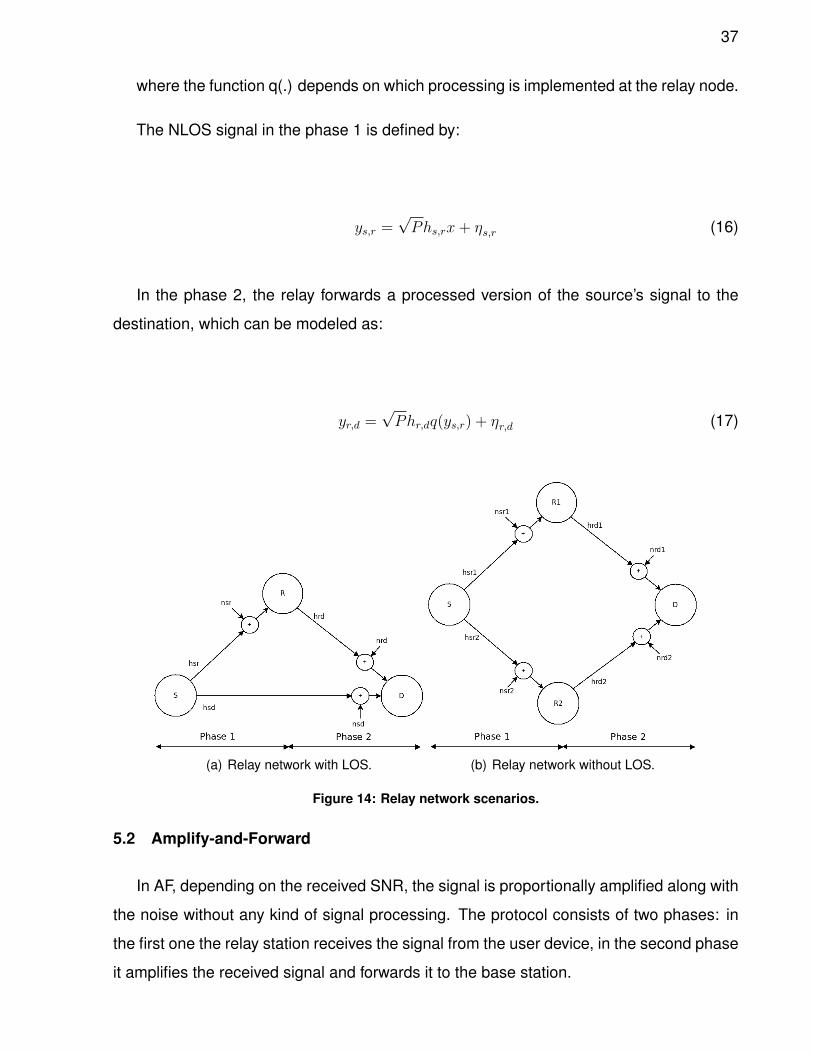
According to the network scenario, the received signal at the destination could be mod-
eled in many ways, for example with or without a LOS among the source and destination,
as shown in Figure 14. The mathematical representation of the received signal with LOS
from source to destination and from source to relay is defined by:
ys,d =√Phs,dx+ ηs,d (13)
ys,r =√Phs,rx+ ηs,r (14)
Where hs,d and hs,r are the channel responses among the source-relay and source-
destination, ηs,d and ηs,r are the additive Gaussian noise with a zero-mean and unit vari-
ance and P the transmission power. In phase 2, the relay forwards a processed version of
the source’s signal to the destination and this can be represented as:
yr,d =√Phr,dq(ys,r) + ηr,d (15)
37
where the function q(.) depends on which processing is implemented at the relay node.
The NLOS signal in the phase 1 is defined by:
ys,r =√Phs,rx+ ηs,r (16)
In the phase 2, the relay forwards a processed version of the source’s signal to the
destination, which can be modeled as:
yr,d =√Phr,dq(ys,r) + ηr,d (17)
(a) Relay network with LOS. (b) Relay network without LOS.
Figure 14: Relay network scenarios.
5.2 Amplify-and-Forward
In AF, depending on the received SNR, the signal is proportionally amplified along with
the noise without any kind of signal processing. The protocol consists of two phases: in
the first one the relay station receives the signal from the user device, in the second phase
it amplifies the received signal and forwards it to the base station.
38
In a scenario where the destination receives a signal from the source and relay nodes,
the received signal at the destination, in the second phase, is a combination from both
nodes given by:
ys,d =√Phs,dx+ ηs,d (18)
ys,r =√Phs,rx+ ηs,r (19)
In phase 2, the relay amplifies the signal from the source and forwards it to the desti-
nation to dismiss the channel fade, in this case, the relay simply scales the received signal
by a factor that is inversely proportional to the received power, which is denoted by:
βr =
√P√
P |hs,r|2 +N0
(20)
In this way, the received signal in the destination at the phase 2 from the relay is given
by:
yr,d = βrhr,dys,r + ηr,d (21)
As previously mentioned, there is a variation of AF named selective AF, where the relay
node is turned off if the received signal is not greater that a SNR threshold. The received
signal at the destination for selective AF is defined by:
39
yr,d = βrhr,dys,r + ηr,d if SNR > threshold (22)
5.3 Decode-and-Forward
In the DF scheme, a relay station demodulates, equalizes (with the source-relay chan-
nel information) and performs channel decoding until the Cyclic Redundancy Check (CRC)
stage is performed. If the CRC of the decoded data is correct, the relay station will per-
form channel coding and will forward the new signal (new CRC) to the base station at the
second phase. In the case of LOS among the source and destination in addition to the
relay-destination link, the received signal in first phase at the destination is given by:
ys,d =√Phs,dx+ ηs,d (23)
ys,r =√Phs,rx+ ηs,r (24)
The received signal at phase 2 in the destination is given by:
yr,d =√Phr,d ¯ys,r + ηr,d (25)
where ¯ys,r is the symbol decoded by the relay node and forwarded to the destination
with a new CRC.
There may be many processes before the CRC stage. We include the following stages
in the relay node for DF: 24 bits CRC insertion, turbo coding, channel interleaving, scram-
bling, digital modulation, DFT precoding, layer mapping and mapping to antennas.
40
In the case of selective DF, the received signal at destination is defined by:
yr,d =√Phr,d ¯ys,r + ηr,d if SNR > threshold (26)
5.4 Equalize-and-Forward
In the EF scheme the symbol received by the relay node only undergoes an equaliza-
tion before being re-transmitted. A relay node receives the OFDM symbol from the user
device at the first phase, then removes the channel effect of the previous phase (source-
relay) in the received signal and finally forwards it to the base station at the second phase.
The received signal at the destination, in the second phase, is given by:
yr,d =√Phr,d ˜ys,r + ηr,d (27)
where ˜ys,r is the symbol equalized on frequency by the relay node and forwarded with-
out the channel effects from phase 1.
For selective EF, the received signal at destination is defined by:
yr,d =√Phr,d ˜ys,r + ηr,d if SNR > threshold (28)
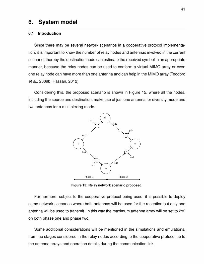
41
6. System model
6.1 Introduction
Since there may be several network scenarios in a cooperative protocol implementa-
tion, it is important to know the number of relay nodes and antennas involved in the current
scenario; thereby the destination node can estimate the received symbol in an appropriate
manner, because the relay nodes can be used to conform a virtual MIMO array or even
one relay node can have more than one antenna and can help in the MIMO array (Teodoro
et al., 2009b; Hassan, 2012).
Considering this, the proposed scenario is shown in Figure 15, where all the nodes,
including the source and destination, make use of just one antenna for diversity mode and
two antennas for a multiplexing mode.
Figure 15: Relay network scenario proposed.
Furthermore, subject to the cooperative protocol being used, it is possible to deploy
some network scenarios where both antennas will be used for the reception but only one
antenna will be used to transmit. In this way the maximum antenna array will be set to 2x2
on both phase one and phase two.
Some additional considerations will be mentioned in the simulations and emulations,
from the stages considered in the relay nodes according to the cooperative protocol up to
the antenna arrays and operation details during the communication link.
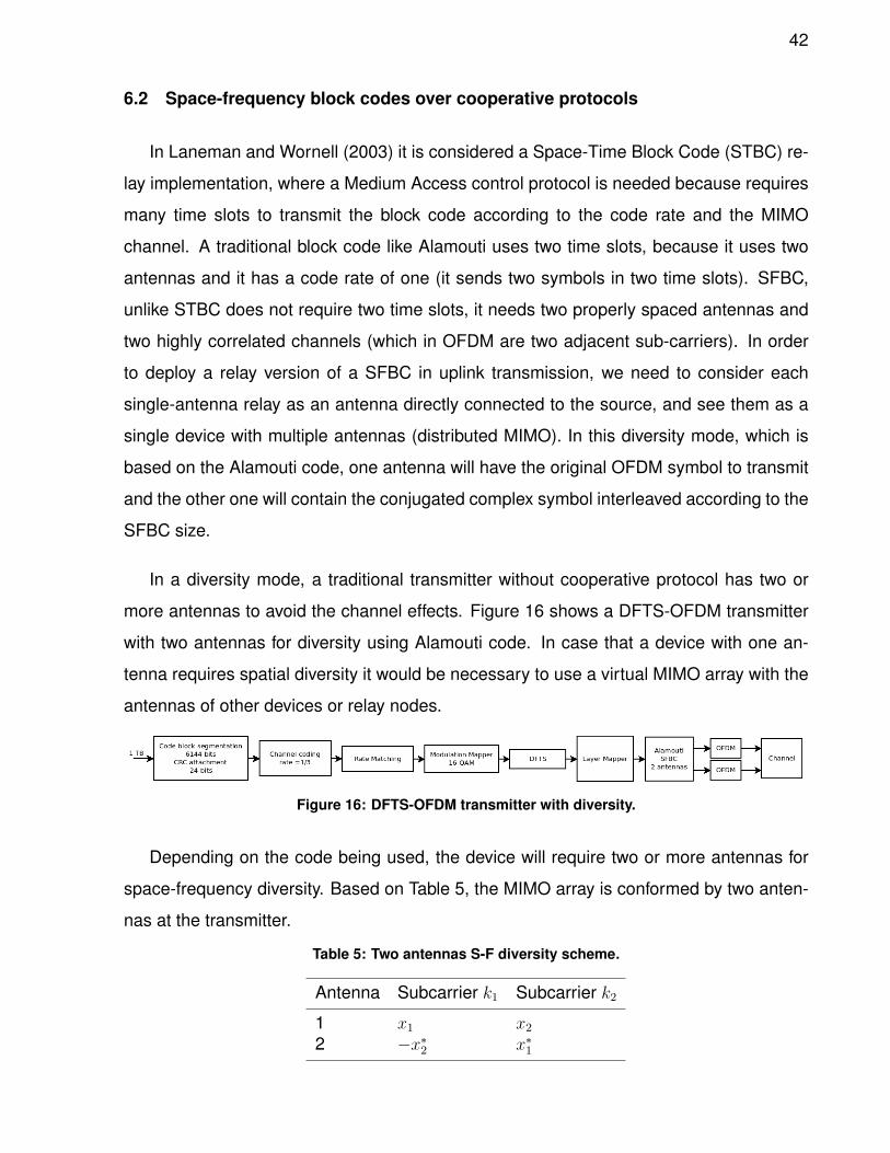
42
6.2 Space-frequency block codes over cooperative protocols
In Laneman and Wornell (2003) it is considered a Space-Time Block Code (STBC) re-
lay implementation, where a Medium Access control protocol is needed because requires
many time slots to transmit the block code according to the code rate and the MIMO
channel. A traditional block code like Alamouti uses two time slots, because it uses two
antennas and it has a code rate of one (it sends two symbols in two time slots). SFBC,
unlike STBC does not require two time slots, it needs two properly spaced antennas and
two highly correlated channels (which in OFDM are two adjacent sub-carriers). In order
to deploy a relay version of a SFBC in uplink transmission, we need to consider each
single-antenna relay as an antenna directly connected to the source, and see them as a
single device with multiple antennas (distributed MIMO). In this diversity mode, which is
based on the Alamouti code, one antenna will have the original OFDM symbol to transmit
and the other one will contain the conjugated complex symbol interleaved according to the
SFBC size.
In a diversity mode, a traditional transmitter without cooperative protocol has two or
more antennas to avoid the channel effects. Figure 16 shows a DFTS-OFDM transmitter
with two antennas for diversity using Alamouti code. In case that a device with one an-
tenna requires spatial diversity it would be necessary to use a virtual MIMO array with the
antennas of other devices or relay nodes.
Figure 16: DFTS-OFDM transmitter with diversity.
Depending on the code being used, the device will require two or more antennas for
space-frequency diversity. Based on Table 5, the MIMO array is conformed by two anten-
nas at the transmitter.
Table 5: Two antennas S-F diversity scheme.
Antenna Subcarrier k1 Subcarrier k2
1 x1 x22 −x∗2 x∗1
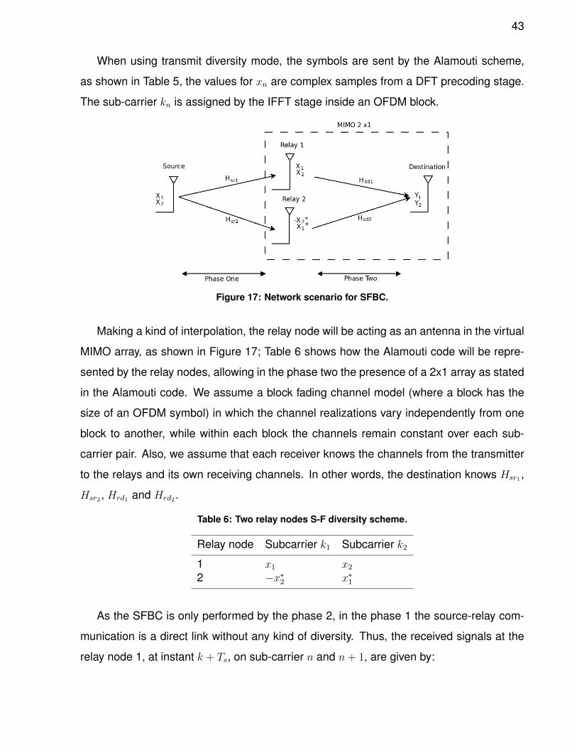
43
When using transmit diversity mode, the symbols are sent by the Alamouti scheme,
as shown in Table 5, the values for xn are complex samples from a DFT precoding stage.
The sub-carrier kn is assigned by the IFFT stage inside an OFDM block.
Figure 17: Network scenario for SFBC.
Making a kind of interpolation, the relay node will be acting as an antenna in the virtual
MIMO array, as shown in Figure 17; Table 6 shows how the Alamouti code will be repre-
sented by the relay nodes, allowing in the phase two the presence of a 2x1 array as stated
in the Alamouti code. We assume a block fading channel model (where a block has the
size of an OFDM symbol) in which the channel realizations vary independently from one
block to another, while within each block the channels remain constant over each sub-
carrier pair. Also, we assume that each receiver knows the channels from the transmitter
to the relays and its own receiving channels. In other words, the destination knows Hsr1 ,
Hsr2, Hrd1 and Hrd2 .
Table 6: Two relay nodes S-F diversity scheme.
Relay node Subcarrier k1 Subcarrier k2
1 x1 x22 −x∗2 x∗1
As the SFBC is only performed by the phase 2, in the phase 1 the source-relay com-
munication is a direct link without any kind of diversity. Thus, the received signals at the
relay node 1, at instant k + Ts, on sub-carrier n and n+ 1, are given by:
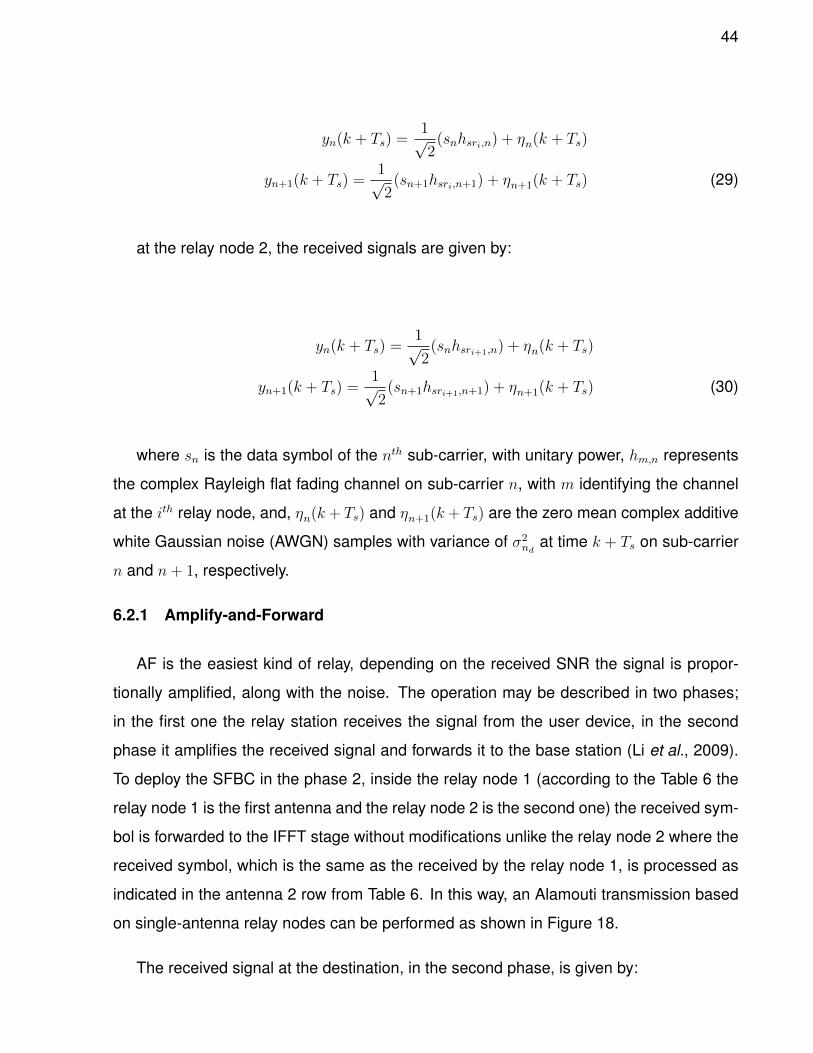
44
yn(k + Ts) =1√2
(snhsri,n) + ηn(k + Ts)
yn+1(k + Ts) =1√2
(sn+1hsri,n+1) + ηn+1(k + Ts) (29)
at the relay node 2, the received signals are given by:
yn(k + Ts) =1√2
(snhsri+1,n) + ηn(k + Ts)
yn+1(k + Ts) =1√2
(sn+1hsri+1,n+1) + ηn+1(k + Ts) (30)
where sn is the data symbol of the nth sub-carrier, with unitary power, hm,n represents
the complex Rayleigh flat fading channel on sub-carrier n, with m identifying the channel
at the ith relay node, and, ηn(k+ Ts) and ηn+1(k+ Ts) are the zero mean complex additive
white Gaussian noise (AWGN) samples with variance of σ2nd
at time k + Ts on sub-carrier
n and n+ 1, respectively.
6.2.1 Amplify-and-Forward
AF is the easiest kind of relay, depending on the received SNR the signal is propor-
tionally amplified, along with the noise. The operation may be described in two phases;
in the first one the relay station receives the signal from the user device, in the second
phase it amplifies the received signal and forwards it to the base station (Li et al., 2009).
To deploy the SFBC in the phase 2, inside the relay node 1 (according to the Table 6 the
relay node 1 is the first antenna and the relay node 2 is the second one) the received sym-
bol is forwarded to the IFFT stage without modifications unlike the relay node 2 where the
received symbol, which is the same as the received by the relay node 1, is processed as
indicated in the antenna 2 row from Table 6. In this way, an Alamouti transmission based
on single-antenna relay nodes can be performed as shown in Figure 18.
The received signal at the destination, in the second phase, is given by:
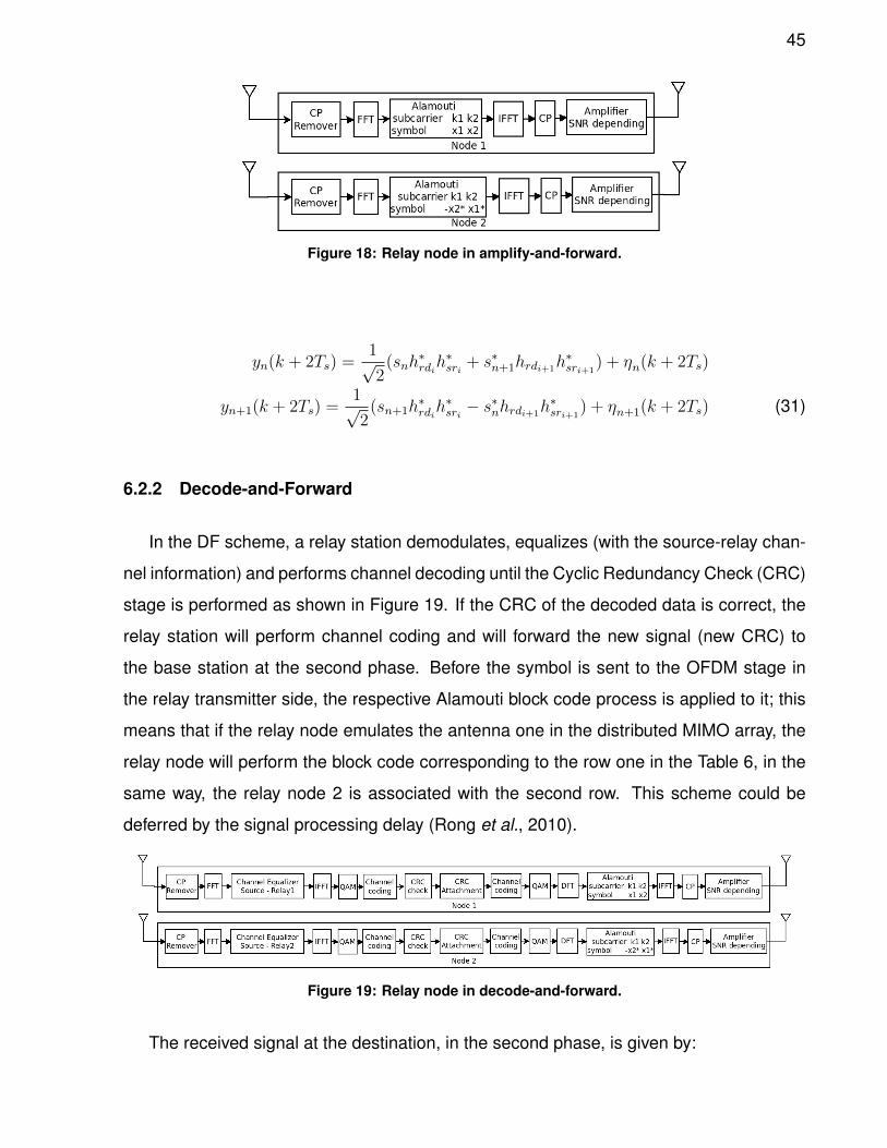
45
Figure 18: Relay node in amplify-and-forward.
yn(k + 2Ts) =1√2
(snh∗rdih∗sri + s∗n+1hrdi+1
h∗sri+1) + ηn(k + 2Ts)
yn+1(k + 2Ts) =1√2
(sn+1h∗rdih∗sri − s
∗nhrdi+1
h∗sri+1) + ηn+1(k + 2Ts) (31)
6.2.2 Decode-and-Forward
In the DF scheme, a relay station demodulates, equalizes (with the source-relay chan-
nel information) and performs channel decoding until the Cyclic Redundancy Check (CRC)
stage is performed as shown in Figure 19. If the CRC of the decoded data is correct, the
relay station will perform channel coding and will forward the new signal (new CRC) to
the base station at the second phase. Before the symbol is sent to the OFDM stage in
the relay transmitter side, the respective Alamouti block code process is applied to it; this
means that if the relay node emulates the antenna one in the distributed MIMO array, the
relay node will perform the block code corresponding to the row one in the Table 6, in the
same way, the relay node 2 is associated with the second row. This scheme could be
deferred by the signal processing delay (Rong et al., 2010).
Figure 19: Relay node in decode-and-forward.
The received signal at the destination, in the second phase, is given by:
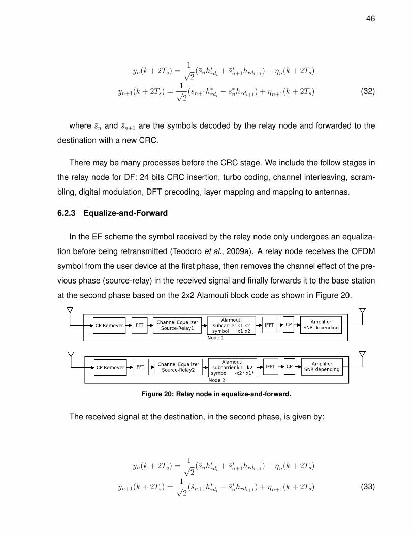
46
yn(k + 2Ts) =1√2
(snh∗rdi
+ s∗n+1hrdi+1) + ηn(k + 2Ts)
yn+1(k + 2Ts) =1√2
(sn+1h∗rdi− s∗nhrdi+1
) + ηn+1(k + 2Ts) (32)
where sn and sn+1 are the symbols decoded by the relay node and forwarded to the
destination with a new CRC.
There may be many processes before the CRC stage. We include the follow stages in
the relay node for DF: 24 bits CRC insertion, turbo coding, channel interleaving, scram-
bling, digital modulation, DFT precoding, layer mapping and mapping to antennas.
6.2.3 Equalize-and-Forward
In the EF scheme the symbol received by the relay node only undergoes an equaliza-
tion before being retransmitted (Teodoro et al., 2009a). A relay node receives the OFDM
symbol from the user device at the first phase, then removes the channel effect of the pre-
vious phase (source-relay) in the received signal and finally forwards it to the base station
at the second phase based on the 2x2 Alamouti block code as shown in Figure 20.
Figure 20: Relay node in equalize-and-forward.
The received signal at the destination, in the second phase, is given by:
yn(k + 2Ts) =1√2
(snh∗rdi
+ s∗n+1hrdi+1) + ηn(k + 2Ts)
yn+1(k + 2Ts) =1√2
(sn+1h∗rdi− s∗nhrdi+1
) + ηn+1(k + 2Ts) (33)
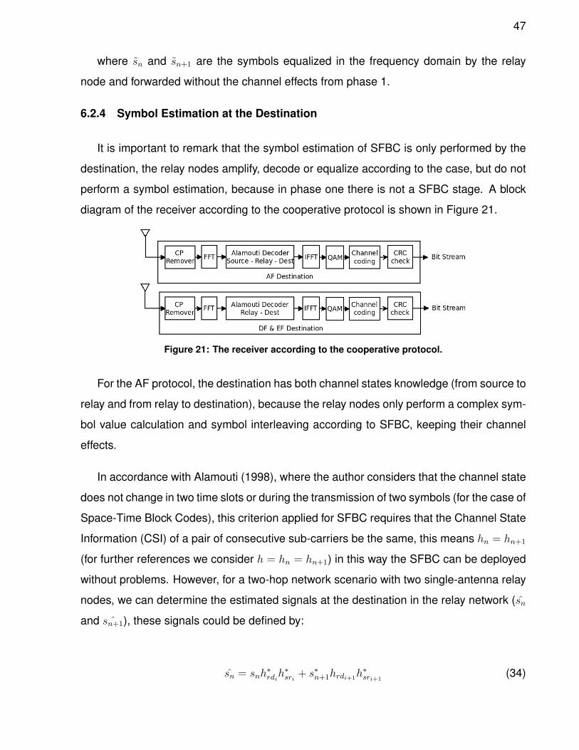
47
where sn and sn+1 are the symbols equalized in the frequency domain by the relay
node and forwarded without the channel effects from phase 1.
6.2.4 Symbol Estimation at the Destination
It is important to remark that the symbol estimation of SFBC is only performed by the
destination, the relay nodes amplify, decode or equalize according to the case, but do not
perform a symbol estimation, because in phase one there is not a SFBC stage. A block
diagram of the receiver according to the cooperative protocol is shown in Figure 21.
Figure 21: The receiver according to the cooperative protocol.
For the AF protocol, the destination has both channel states knowledge (from source to
relay and from relay to destination), because the relay nodes only perform a complex sym-
bol value calculation and symbol interleaving according to SFBC, keeping their channel
effects.
In accordance with Alamouti (1998), where the author considers that the channel state
does not change in two time slots or during the transmission of two symbols (for the case of
Space-Time Block Codes), this criterion applied for SFBC requires that the Channel State
Information (CSI) of a pair of consecutive sub-carriers be the same, this means hn = hn+1
(for further references we consider h = hn = hn+1) in this way the SFBC can be deployed
without problems. However, for a two-hop network scenario with two single-antenna relay
nodes, we can determine the estimated signals at the destination in the relay network (sn
and ˆsn+1), these signals could be defined by:
sn = snh∗rdih∗sri + s∗n+1hrdi+1
h∗sri+1(34)
48
ˆsn+1 = sn+1h∗rdih∗sri − s
∗nhrdi+1
h∗sri+1(35)
where sn and sn+1 are the signals received by the ith destination node and that were
transmitted by the relays in the second phase at two consecutive sub-carriers,
sn = xi,nhrdi − x∗i+1,n+1hrdi+1+ ηn (36)
sn+1 = xi,n+1hrdi − x∗i+1,nhrdi+1+ ηn+1 (37)
where ηn and ηn+1 represent complex noise and interference at the kn and kn+1 sub-
carriers in the antenna receiver. The signals received by the relay nodes and transmitted
from the source in phase one are defined by:
xi,n = xnhsri + ηn (38)
xi,n+1 = xn+1hsri + ηn+1 (39)
xi+1,n = xnhsri+1+ ηn (40)
xi+1,n+1 = xn+1hsri+1+ ηn+1 (41)
where xi,n is the data symbol of the ith relay node at the nth sub-carrier.
Substituting (36) and (37) in (34),
49
sn = (xi,nhrdi − x∗i+1,n+1hrdi+1+ ηn)h∗rdih
∗sri
+ (xi,n+1hrdi − x∗i+1,nhrdi + ηi+1)∗hrdi+1
h∗sri+1(42)
replacing (38), (39), (40) and (41) in (42),
sn = xn(|hsri |2|hrdi |2 + |hsri+1|2|hrdi+1
|2) + η (43)
where:
η = ηnh∗srih∗rdi + η∗n+1hsri+1
h∗rdi+1+ ηn|hsri |2hrdi
+ ηn+1h∗srihsri+1
hrdi+1+ ηn|hsri+1
|2hrdi+1+ η∗n+1h
∗srihsri+1
h∗rdi (44)
For estimating ˆsn+1, a similar process must be followed, starting at (35).
The channel estimation in the AF protocol for the two phases can be described as
follow: first the destination sends the training sequence to the relay node and estimates
the relay-destination channel, then the destination sends again the training sequence to
the relay node and the relay node forwards that sequence to the source, the source for-
wards these sequence to the relay node and the relay node forwards the sequence to the
destination. Once the destination has the relay-destination CSI, it can mitigate its effect
leaving only the source-relay channel effects; in this way the destination can know the
source-relay-destination CSI (Koyuncu et al., 2008)
In both, the DF and EF cases, we can not use this process because the source-relay
channel is mitigated by the relay node in phase one and the symbol presented in phase
two is corrected by the node in its transmission stage, therefore the estimated signal in the
destination at phase two is defined as:
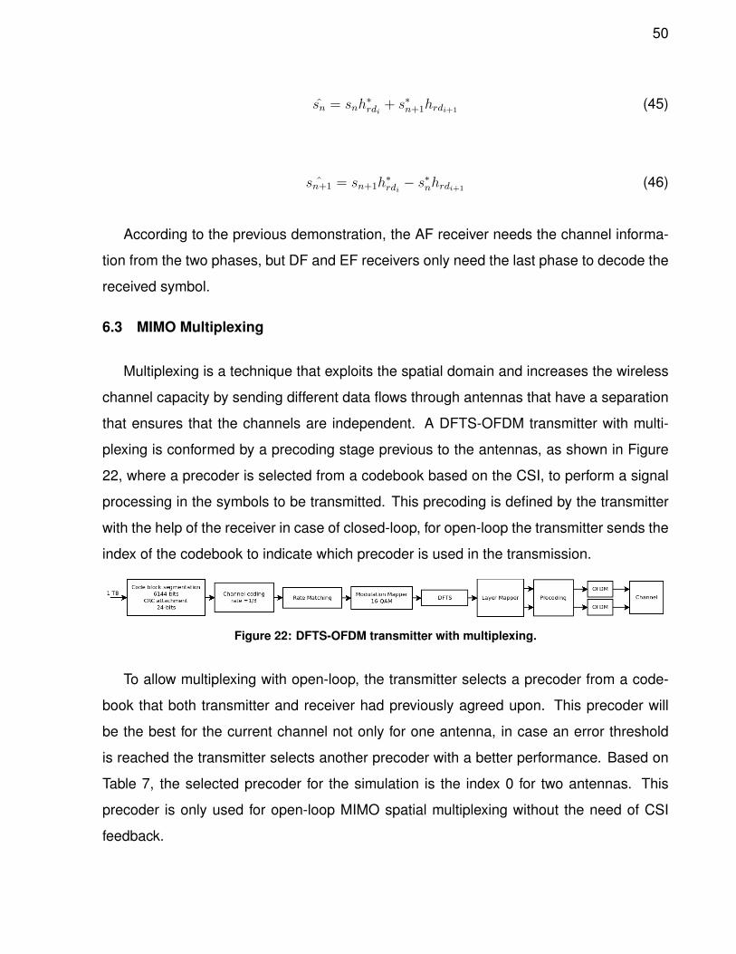
50
sn = snh∗rdi
+ s∗n+1hrdi+1(45)
ˆsn+1 = sn+1h∗rdi− s∗nhrdi+1
(46)
According to the previous demonstration, the AF receiver needs the channel informa-
tion from the two phases, but DF and EF receivers only need the last phase to decode the
received symbol.
6.3 MIMO Multiplexing
Multiplexing is a technique that exploits the spatial domain and increases the wireless
channel capacity by sending different data flows through antennas that have a separation
that ensures that the channels are independent. A DFTS-OFDM transmitter with multi-
plexing is conformed by a precoding stage previous to the antennas, as shown in Figure
22, where a precoder is selected from a codebook based on the CSI, to perform a signal
processing in the symbols to be transmitted. This precoding is defined by the transmitter
with the help of the receiver in case of closed-loop, for open-loop the transmitter sends the
index of the codebook to indicate which precoder is used in the transmission.
Figure 22: DFTS-OFDM transmitter with multiplexing.
To allow multiplexing with open-loop, the transmitter selects a precoder from a code-
book that both transmitter and receiver had previously agreed upon. This precoder will
be the best for the current channel not only for one antenna, in case an error threshold
is reached the transmitter selects another precoder with a better performance. Based on
Table 7, the selected precoder for the simulation is the index 0 for two antennas. This
precoder is only used for open-loop MIMO spatial multiplexing without the need of CSI
feedback.
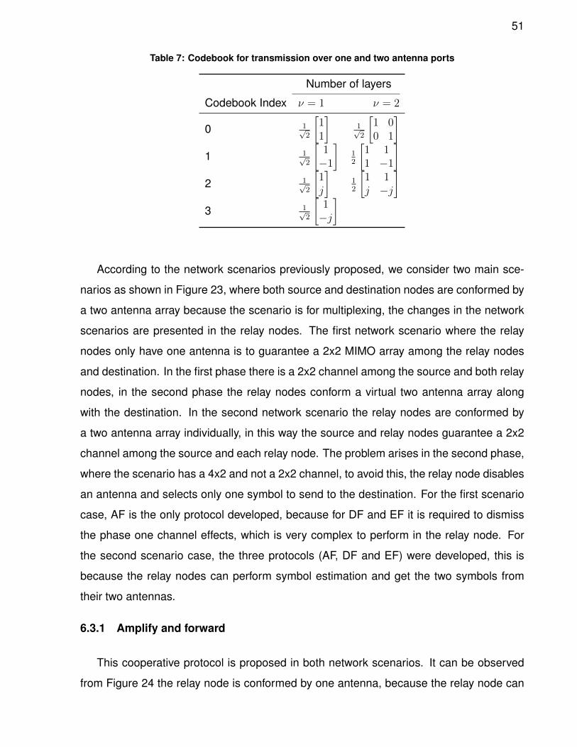
51
Table 7: Codebook for transmission over one and two antenna ports
Number of layers
Codebook Index ν = 1 ν = 2
0 1√2
[11
]1√2
[1 00 1
]1 1√
2
[1−1
]12
[1 11 −1
]2 1√
2
[1j
]12
[1 1j −j
]3 1√
2
[1−j
]
According to the network scenarios previously proposed, we consider two main sce-
narios as shown in Figure 23, where both source and destination nodes are conformed by
a two antenna array because the scenario is for multiplexing, the changes in the network
scenarios are presented in the relay nodes. The first network scenario where the relay
nodes only have one antenna is to guarantee a 2x2 MIMO array among the relay nodes
and destination. In the first phase there is a 2x2 channel among the source and both relay
nodes, in the second phase the relay nodes conform a virtual two antenna array along
with the destination. In the second network scenario the relay nodes are conformed by
a two antenna array individually, in this way the source and relay nodes guarantee a 2x2
channel among the source and each relay node. The problem arises in the second phase,
where the scenario has a 4x2 and not a 2x2 channel, to avoid this, the relay node disables
an antenna and selects only one symbol to send to the destination. For the first scenario
case, AF is the only protocol developed, because for DF and EF it is required to dismiss
the phase one channel effects, which is very complex to perform in the relay node. For
the second scenario case, the three protocols (AF, DF and EF) were developed, this is
because the relay nodes can perform symbol estimation and get the two symbols from
their two antennas.
6.3.1 Amplify and forward
This cooperative protocol is proposed in both network scenarios. It can be observed
from Figure 24 the relay node is conformed by one antenna, because the relay node can
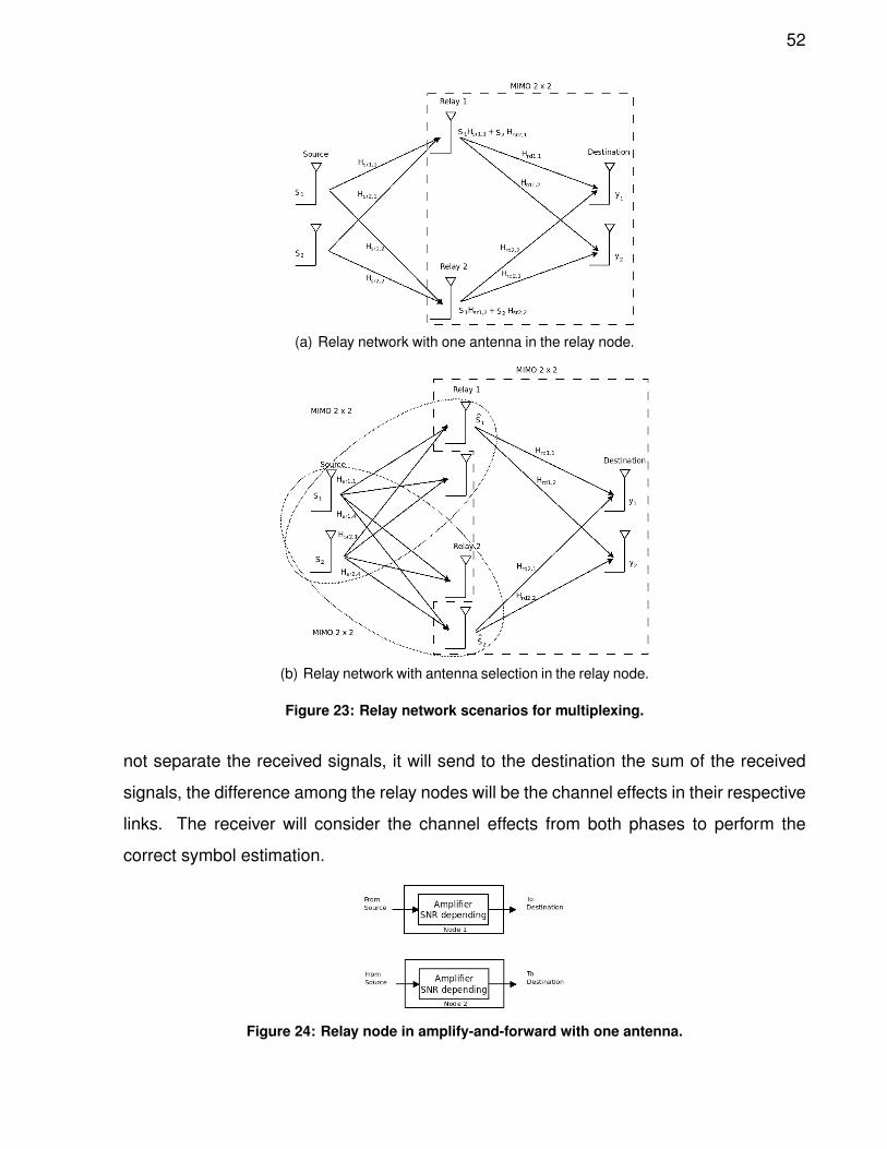
52
(a) Relay network with one antenna in the relay node.
(b) Relay network with antenna selection in the relay node.
Figure 23: Relay network scenarios for multiplexing.
not separate the received signals, it will send to the destination the sum of the received
signals, the difference among the relay nodes will be the channel effects in their respective
links. The receiver will consider the channel effects from both phases to perform the
correct symbol estimation.
Figure 24: Relay node in amplify-and-forward with one antenna.
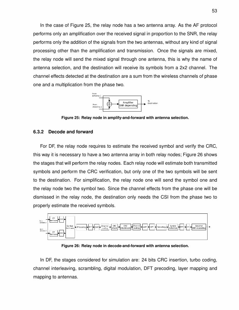
53
In the case of Figure 25, the relay node has a two antenna array. As the AF protocol
performs only an amplification over the received signal in proportion to the SNR, the relay
performs only the addition of the signals from the two antennas, without any kind of signal
processing other than the amplification and transmission. Once the signals are mixed,
the relay node will send the mixed signal through one antenna, this is why the name of
antenna selection, and the destination will receive its symbols from a 2x2 channel. The
channel effects detected at the destination are a sum from the wireless channels of phase
one and a multiplication from the phase two.
Figure 25: Relay node in amplify-and-forward with antenna selection.
6.3.2 Decode and forward
For DF, the relay node requires to estimate the received symbol and verify the CRC,
this way it is necessary to have a two antenna array in both relay nodes; Figure 26 shows
the stages that will perform the relay nodes. Each relay node will estimate both transmitted
symbols and perform the CRC verification, but only one of the two symbols will be sent
to the destination. For simplification, the relay node one will send the symbol one and
the relay node two the symbol two. Since the channel effects from the phase one will be
dismissed in the relay node, the destination only needs the CSI from the phase two to
properly estimate the received symbols.
Figure 26: Relay node in decode-and-forward with antenna selection.
In DF, the stages considered for simulation are: 24 bits CRC insertion, turbo coding,
channel interleaving, scrambling, digital modulation, DFT precoding, layer mapping and
mapping to antennas.
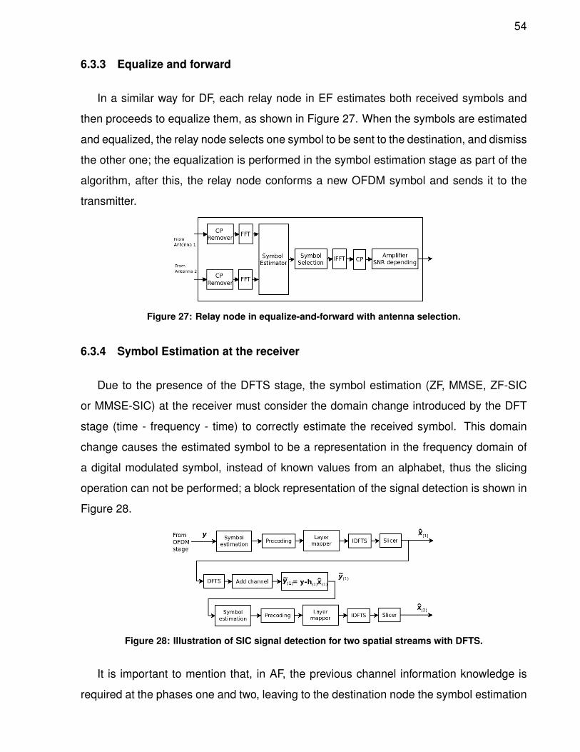
54
6.3.3 Equalize and forward
In a similar way for DF, each relay node in EF estimates both received symbols and
then proceeds to equalize them, as shown in Figure 27. When the symbols are estimated
and equalized, the relay node selects one symbol to be sent to the destination, and dismiss
the other one; the equalization is performed in the symbol estimation stage as part of the
algorithm, after this, the relay node conforms a new OFDM symbol and sends it to the
transmitter.
Figure 27: Relay node in equalize-and-forward with antenna selection.
6.3.4 Symbol Estimation at the receiver
Due to the presence of the DFTS stage, the symbol estimation (ZF, MMSE, ZF-SIC
or MMSE-SIC) at the receiver must consider the domain change introduced by the DFT
stage (time - frequency - time) to correctly estimate the received symbol. This domain
change causes the estimated symbol to be a representation in the frequency domain of
a digital modulated symbol, instead of known values from an alphabet, thus the slicing
operation can not be performed; a block representation of the signal detection is shown in
Figure 28.
Figure 28: Illustration of SIC signal detection for two spatial streams with DFTS.
It is important to mention that, in AF, the previous channel information knowledge is
required at the phases one and two, leaving to the destination node the symbol estimation
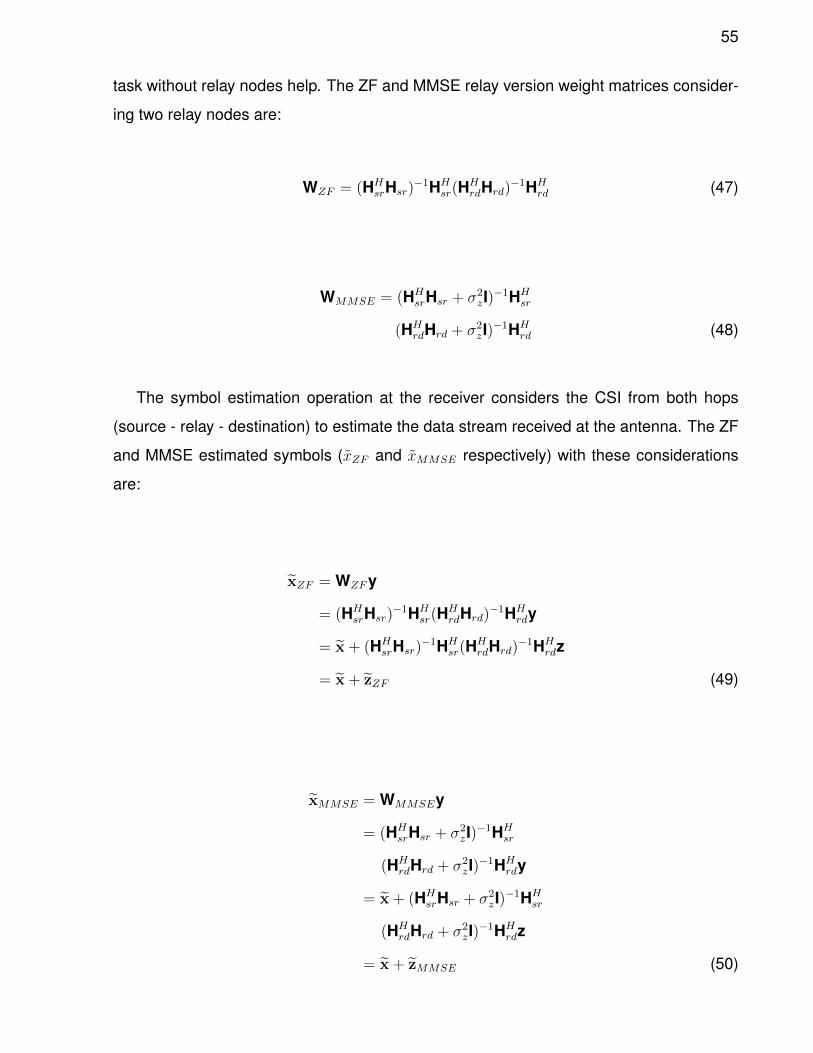
55
task without relay nodes help. The ZF and MMSE relay version weight matrices consider-
ing two relay nodes are:
WZF = (HHsrHsr)
−1HHsr(H
HrdHrd)
−1HHrd (47)
WMMSE = (HHsrHsr + σ2
zI)−1HH
sr
(HHrdHrd + σ2
zI)−1HH
rd (48)
The symbol estimation operation at the receiver considers the CSI from both hops
(source - relay - destination) to estimate the data stream received at the antenna. The ZF
and MMSE estimated symbols (xZF and xMMSE respectively) with these considerations
are:
xZF = WZFy
= (HHsrHsr)
−1HHsr(H
HrdHrd)
−1HHrdy
= x + (HHsrHsr)
−1HHsr(H
HrdHrd)
−1HHrdz
= x + zZF (49)
xMMSE = WMMSEy
= (HHsrHsr + σ2
zI)−1HH
sr
(HHrdHrd + σ2
zI)−1HH
rdy
= x + (HHsrHsr + σ2
zI)−1HH
sr
(HHrdHrd + σ2
zI)−1HH
rdz
= x + zMMSE (50)

56
where y is the received symbol and z represents the noise. DF and EF do not require
the source-relay channel state information, this is because the relay node estimates the
symbol received after hop 1 and therefore mitigates the channel effects.
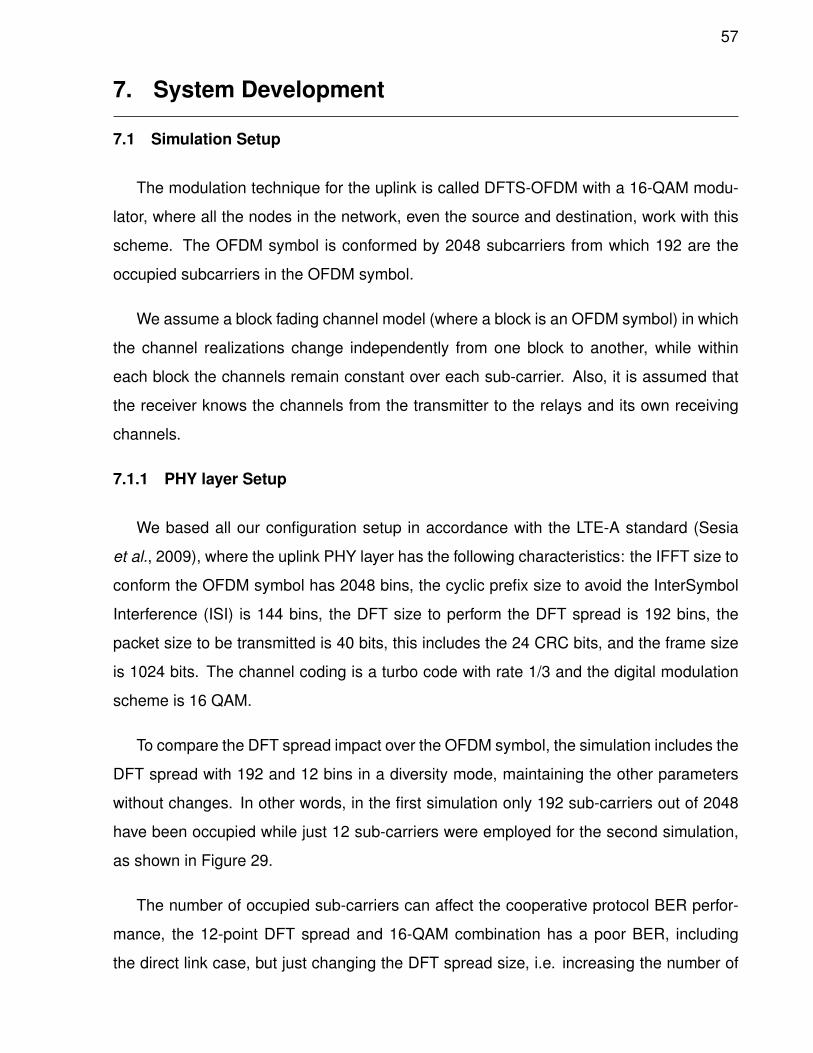
57
7. System Development
7.1 Simulation Setup
The modulation technique for the uplink is called DFTS-OFDM with a 16-QAM modu-
lator, where all the nodes in the network, even the source and destination, work with this
scheme. The OFDM symbol is conformed by 2048 subcarriers from which 192 are the
occupied subcarriers in the OFDM symbol.
We assume a block fading channel model (where a block is an OFDM symbol) in which
the channel realizations change independently from one block to another, while within
each block the channels remain constant over each sub-carrier. Also, it is assumed that
the receiver knows the channels from the transmitter to the relays and its own receiving
channels.
7.1.1 PHY layer Setup
We based all our configuration setup in accordance with the LTE-A standard (Sesia
et al., 2009), where the uplink PHY layer has the following characteristics: the IFFT size to
conform the OFDM symbol has 2048 bins, the cyclic prefix size to avoid the InterSymbol
Interference (ISI) is 144 bins, the DFT size to perform the DFT spread is 192 bins, the
packet size to be transmitted is 40 bits, this includes the 24 CRC bits, and the frame size
is 1024 bits. The channel coding is a turbo code with rate 1/3 and the digital modulation
scheme is 16 QAM.
To compare the DFT spread impact over the OFDM symbol, the simulation includes the
DFT spread with 192 and 12 bins in a diversity mode, maintaining the other parameters
without changes. In other words, in the first simulation only 192 sub-carriers out of 2048
have been occupied while just 12 sub-carriers were employed for the second simulation,
as shown in Figure 29.
The number of occupied sub-carriers can affect the cooperative protocol BER perfor-
mance, the 12-point DFT spread and 16-QAM combination has a poor BER, including
the direct link case, but just changing the DFT spread size, i.e. increasing the number of
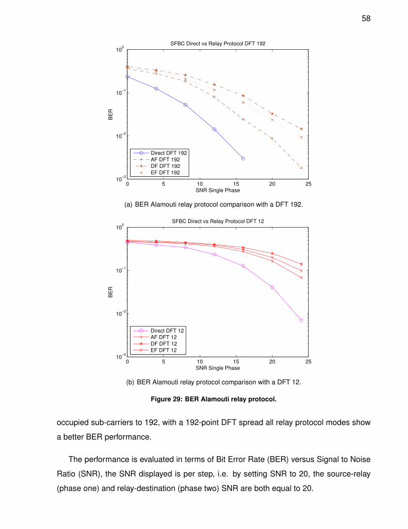
58
0 5 10 15 20 2510
−3
10−2
10−1
100
SNR Single Phase
BE
R
SFBC Direct vs Relay Protocol DFT 192
Direct DFT 192
AF DFT 192
DF DFT 192
EF DFT 192
(a) BER Alamouti relay protocol comparison with a DFT 192.
0 5 10 15 20 2510
−3
10−2
10−1
100
SNR Single Phase
BE
R
SFBC Direct vs Relay Protocol DFT 12
Direct DFT 12
AF DFT 12
DF DFT 12
EF DFT 12
(b) BER Alamouti relay protocol comparison with a DFT 12.
Figure 29: BER Alamouti relay protocol.
occupied sub-carriers to 192, with a 192-point DFT spread all relay protocol modes show
a better BER performance.
The performance is evaluated in terms of Bit Error Rate (BER) versus Signal to Noise
Ratio (SNR), the SNR displayed is per step, i.e. by setting SNR to 20, the source-relay
(phase one) and relay-destination (phase two) SNR are both equal to 20.
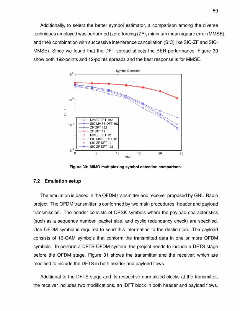
59
Additionally, to select the better symbol estimator, a comparison among the diverse
techniques employed was performed (zero-forcing (ZF), minimum mean square error (MMSE),
and their combination with successive interference cancellation (SIC) like SIC-ZF and SIC-
MMSE). Since we found that the DFT spread affects the BER performance, Figure 30
show both 192-points and 12-points spreads and the best response is for MMSE.
0 5 10 15 20 2510
−3
10−2
10−1
100
SNR
BE
R
Symbol Detection
MMSE DFT 192
SIC MMSE DFT 192
ZF DFT 192
ZF DFT 12
MMSE DFT 12
SIC MMSE DFT 12
SIC ZF DFT 12
SIC ZF DFT 192
Figure 30: MIMO multiplexing symbol detection comparison.
7.2 Emulation setup
The emulation is based in the OFDM transmitter and receiver proposed by GNU Radio
project. The OFDM transmitter is conformed by two main procedures: header and payload
transmission. The header consists of QPSK symbols where the payload characteristics
(such as a sequence number, packet size, and cyclic redundancy check) are specified.
One OFDM symbol is required to send this information to the destination. The payload
consists of 16-QAM symbols that conform the transmitted data in one or more OFDM
symbols. To perform a DFTS-OFDM system, the project needs to include a DFTS stage
before the OFDM stage, Figure 31 shows the transmitter and the receiver, which are
modified to include the DFTS in both header and payload flows.
Additional to the DFTS stage and its respective normalized blocks at the transmitter,
the receiver includes two modifications, an IDFT block in both header and payload flows,
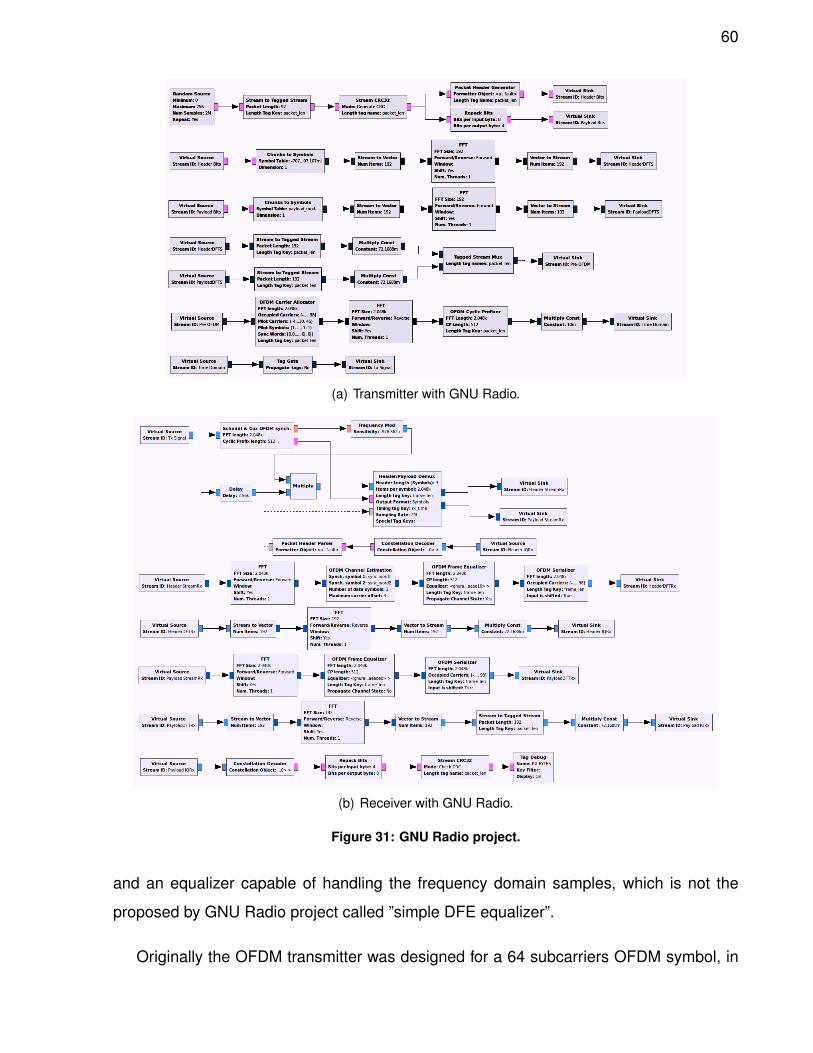
60
(a) Transmitter with GNU Radio.
(b) Receiver with GNU Radio.
Figure 31: GNU Radio project.
and an equalizer capable of handling the frequency domain samples, which is not the
proposed by GNU Radio project called ”simple DFE equalizer”.
Originally the OFDM transmitter was designed for a 64 subcarriers OFDM symbol, in
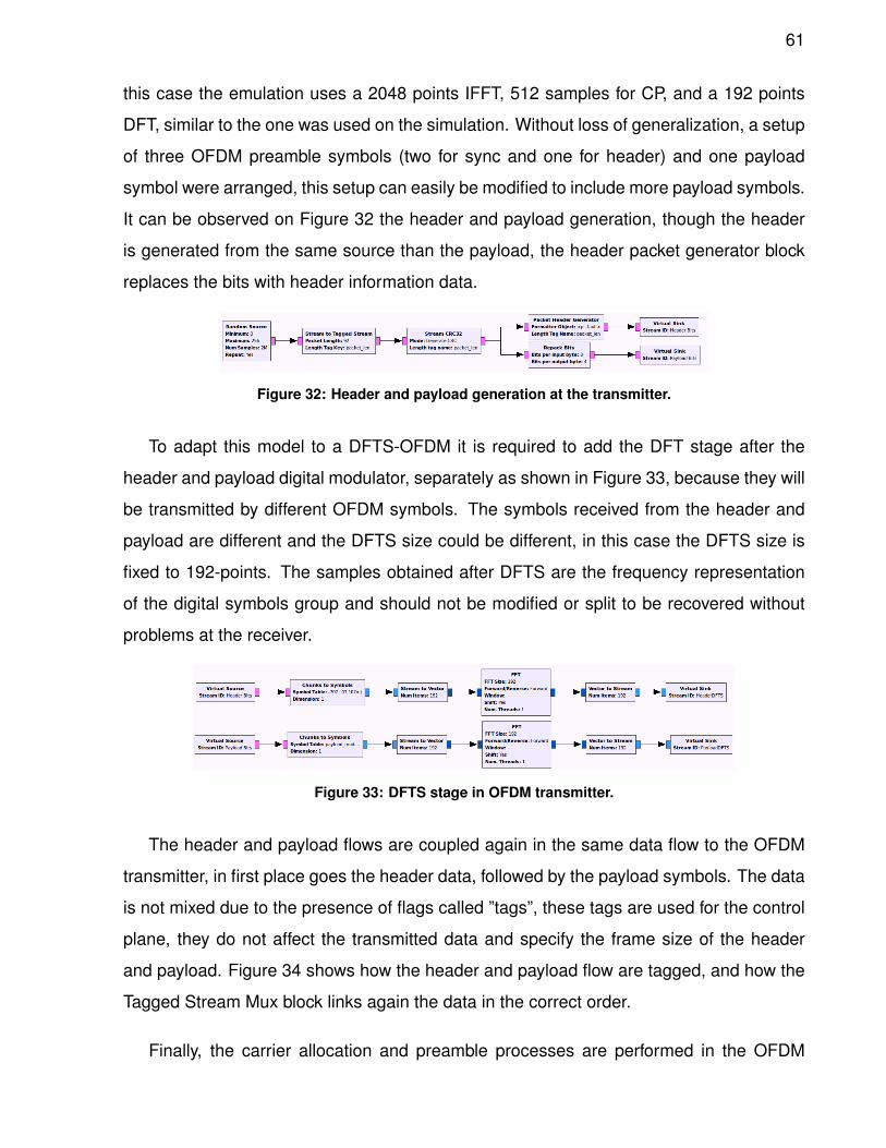
61
this case the emulation uses a 2048 points IFFT, 512 samples for CP, and a 192 points
DFT, similar to the one was used on the simulation. Without loss of generalization, a setup
of three OFDM preamble symbols (two for sync and one for header) and one payload
symbol were arranged, this setup can easily be modified to include more payload symbols.
It can be observed on Figure 32 the header and payload generation, though the header
is generated from the same source than the payload, the header packet generator block
replaces the bits with header information data.
Figure 32: Header and payload generation at the transmitter.
To adapt this model to a DFTS-OFDM it is required to add the DFT stage after the
header and payload digital modulator, separately as shown in Figure 33, because they will
be transmitted by different OFDM symbols. The symbols received from the header and
payload are different and the DFTS size could be different, in this case the DFTS size is
fixed to 192-points. The samples obtained after DFTS are the frequency representation
of the digital symbols group and should not be modified or split to be recovered without
problems at the receiver.
Figure 33: DFTS stage in OFDM transmitter.
The header and payload flows are coupled again in the same data flow to the OFDM
transmitter, in first place goes the header data, followed by the payload symbols. The data
is not mixed due to the presence of flags called ”tags”, these tags are used for the control
plane, they do not affect the transmitted data and specify the frame size of the header
and payload. Figure 34 shows how the header and payload flow are tagged, and how the
Tagged Stream Mux block links again the data in the correct order.
Finally, the carrier allocation and preamble processes are performed in the OFDM
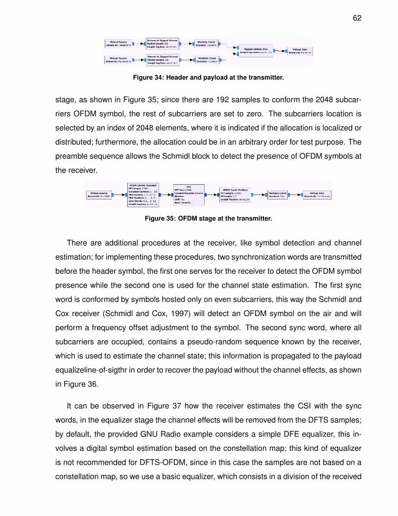
62
Figure 34: Header and payload at the transmitter.
stage, as shown in Figure 35; since there are 192 samples to conform the 2048 subcar-
riers OFDM symbol, the rest of subcarriers are set to zero. The subcarriers location is
selected by an index of 2048 elements, where it is indicated if the allocation is localized or
distributed; furthermore, the allocation could be in an arbitrary order for test purpose. The
preamble sequence allows the Schmidl block to detect the presence of OFDM symbols at
the receiver.
Figure 35: OFDM stage at the transmitter.
There are additional procedures at the receiver, like symbol detection and channel
estimation; for implementing these procedures, two synchronization words are transmitted
before the header symbol, the first one serves for the receiver to detect the OFDM symbol
presence while the second one is used for the channel state estimation. The first sync
word is conformed by symbols hosted only on even subcarriers, this way the Schmidl and
Cox receiver (Schmidl and Cox, 1997) will detect an OFDM symbol on the air and will
perform a frequency offset adjustment to the symbol. The second sync word, where all
subcarriers are occupied, contains a pseudo-random sequence known by the receiver,
which is used to estimate the channel state; this information is propagated to the payload
equalizeline-of-sigthr in order to recover the payload without the channel effects, as shown
in Figure 36.
It can be observed in Figure 37 how the receiver estimates the CSI with the sync
words, in the equalizer stage the channel effects will be removed from the DFTS samples;
by default, the provided GNU Radio example considers a simple DFE equalizer, this in-
volves a digital symbol estimation based on the constellation map; this kind of equalizer
is not recommended for DFTS-OFDM, since in this case the samples are not based on a
constellation map, so we use a basic equalizer, which consists in a division of the received
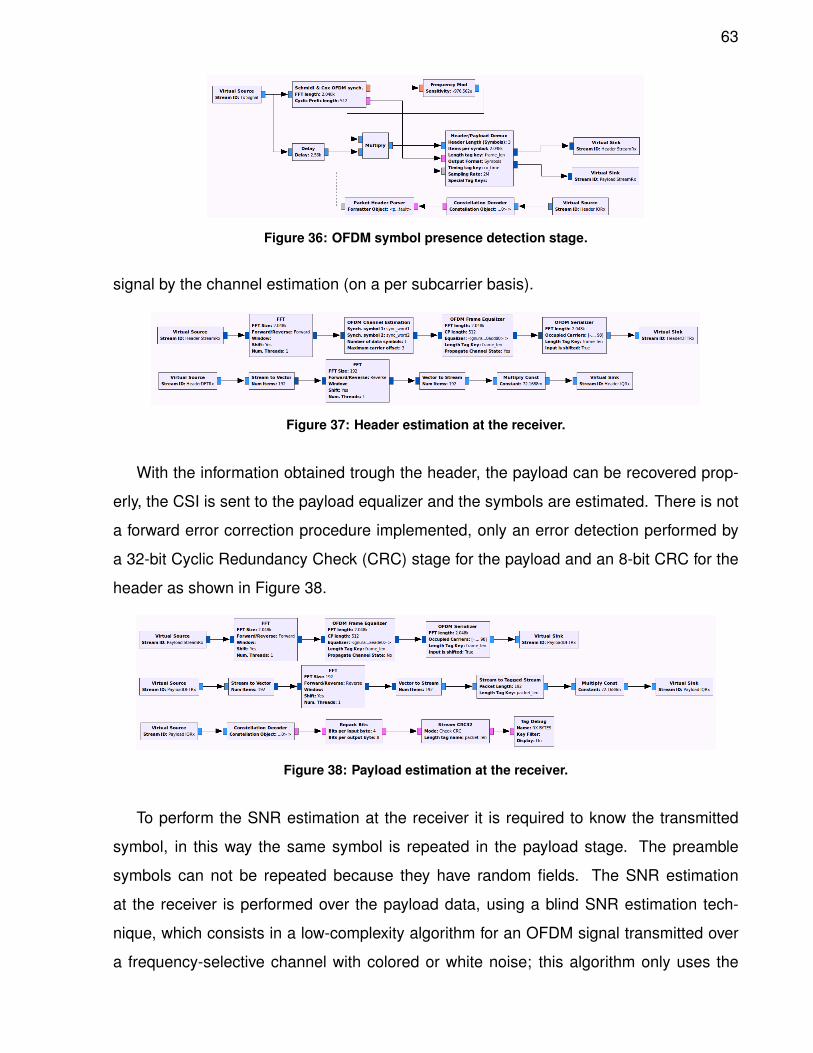
63
Figure 36: OFDM symbol presence detection stage.
signal by the channel estimation (on a per subcarrier basis).
Figure 37: Header estimation at the receiver.
With the information obtained trough the header, the payload can be recovered prop-
erly, the CSI is sent to the payload equalizer and the symbols are estimated. There is not
a forward error correction procedure implemented, only an error detection performed by
a 32-bit Cyclic Redundancy Check (CRC) stage for the payload and an 8-bit CRC for the
header as shown in Figure 38.
Figure 38: Payload estimation at the receiver.
To perform the SNR estimation at the receiver it is required to know the transmitted
symbol, in this way the same symbol is repeated in the payload stage. The preamble
symbols can not be repeated because they have random fields. The SNR estimation
at the receiver is performed over the payload data, using a blind SNR estimation tech-
nique, which consists in a low-complexity algorithm for an OFDM signal transmitted over
a frequency-selective channel with colored or white noise; this algorithm only uses the
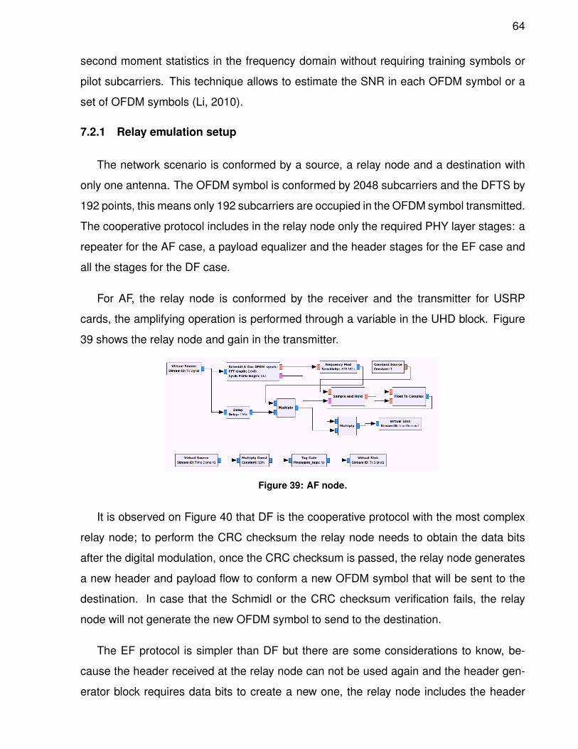
64
second moment statistics in the frequency domain without requiring training symbols or
pilot subcarriers. This technique allows to estimate the SNR in each OFDM symbol or a
set of OFDM symbols (Li, 2010).
7.2.1 Relay emulation setup
The network scenario is conformed by a source, a relay node and a destination with
only one antenna. The OFDM symbol is conformed by 2048 subcarriers and the DFTS by
192 points, this means only 192 subcarriers are occupied in the OFDM symbol transmitted.
The cooperative protocol includes in the relay node only the required PHY layer stages: a
repeater for the AF case, a payload equalizer and the header stages for the EF case and
all the stages for the DF case.
For AF, the relay node is conformed by the receiver and the transmitter for USRP
cards, the amplifying operation is performed through a variable in the UHD block. Figure
39 shows the relay node and gain in the transmitter.
Figure 39: AF node.
It is observed on Figure 40 that DF is the cooperative protocol with the most complex
relay node; to perform the CRC checksum the relay node needs to obtain the data bits
after the digital modulation, once the CRC checksum is passed, the relay node generates
a new header and payload flow to conform a new OFDM symbol that will be sent to the
destination. In case that the Schmidl or the CRC checksum verification fails, the relay
node will not generate the new OFDM symbol to send to the destination.
The EF protocol is simpler than DF but there are some considerations to know, be-
cause the header received at the relay node can not be used again and the header gen-
erator block requires data bits to create a new one, the relay node includes the header
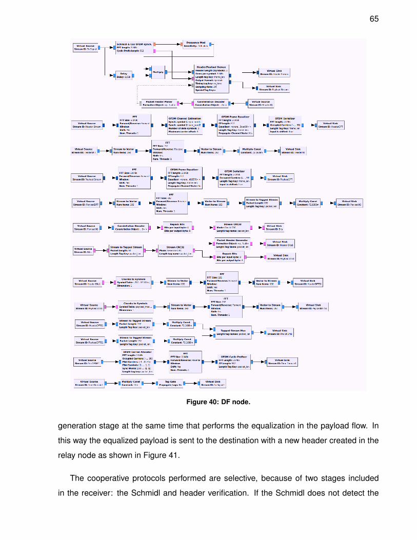
65
Figure 40: DF node.
generation stage at the same time that performs the equalization in the payload flow. In
this way the equalized payload is sent to the destination with a new header created in the
relay node as shown in Figure 41.
The cooperative protocols performed are selective, because of two stages included
in the receiver: the Schmidl and header verification. If the Schmidl does not detect the
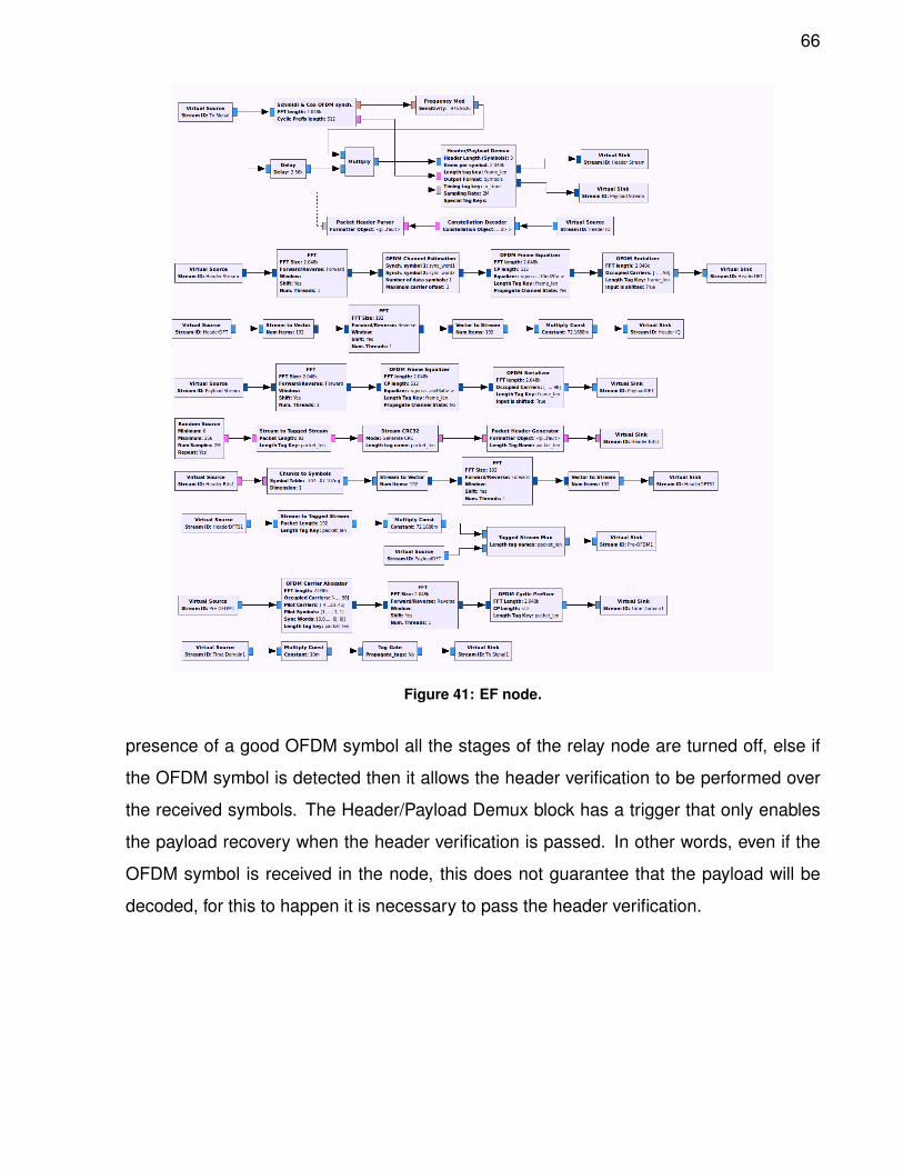
66
Figure 41: EF node.
presence of a good OFDM symbol all the stages of the relay node are turned off, else if
the OFDM symbol is detected then it allows the header verification to be performed over
the received symbols. The Header/Payload Demux block has a trigger that only enables
the payload recovery when the header verification is passed. In other words, even if the
OFDM symbol is received in the node, this does not guarantee that the payload will be
decoded, for this to happen it is necessary to pass the header verification.
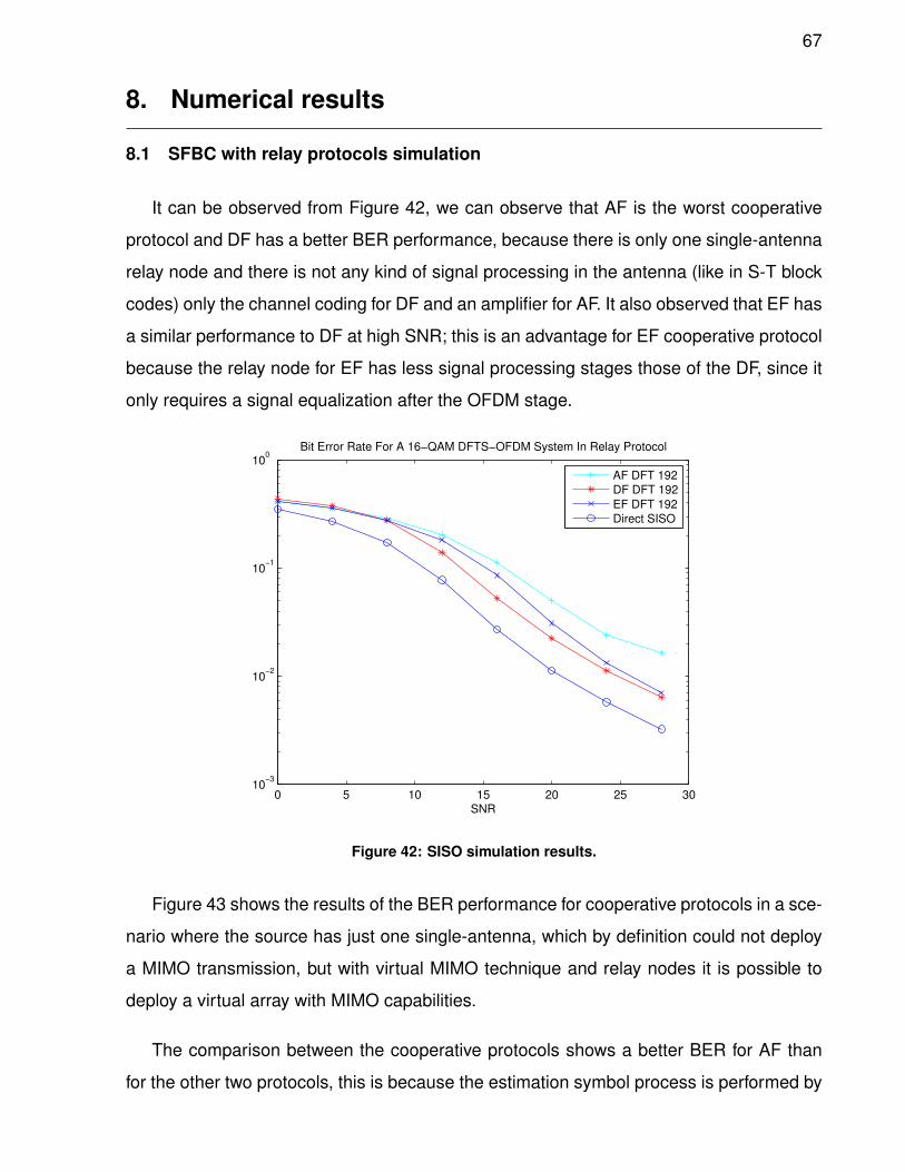
67
8. Numerical results
8.1 SFBC with relay protocols simulation
It can be observed from Figure 42, we can observe that AF is the worst cooperative
protocol and DF has a better BER performance, because there is only one single-antenna
relay node and there is not any kind of signal processing in the antenna (like in S-T block
codes) only the channel coding for DF and an amplifier for AF. It also observed that EF has
a similar performance to DF at high SNR; this is an advantage for EF cooperative protocol
because the relay node for EF has less signal processing stages those of the DF, since it
only requires a signal equalization after the OFDM stage.
0 5 10 15 20 25 3010
−3
10−2
10−1
100
SNR
Bit Error Rate For A 16−QAM DFTS−OFDM System In Relay Protocol
AF DFT 192
DF DFT 192
EF DFT 192
Direct SISO
Figure 42: SISO simulation results.
Figure 43 shows the results of the BER performance for cooperative protocols in a sce-
nario where the source has just one single-antenna, which by definition could not deploy
a MIMO transmission, but with virtual MIMO technique and relay nodes it is possible to
deploy a virtual array with MIMO capabilities.
The comparison between the cooperative protocols shows a better BER for AF than
for the other two protocols, this is because the estimation symbol process is performed by
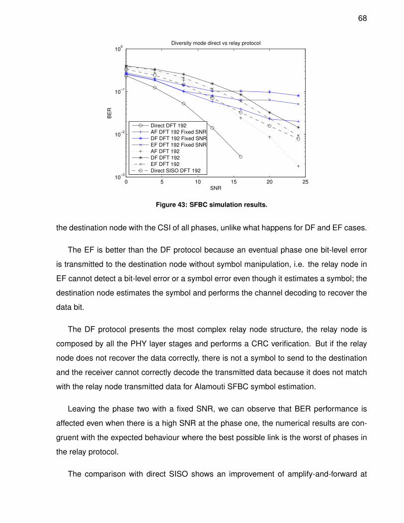
68
0 5 10 15 20 2510
−3
10−2
10−1
100
SNR
BE
R
Diversity mode direct vs relay protocol
Direct DFT 192
AF DFT 192 Fixed SNR
DF DFT 192 Fixed SNR
EF DFT 192 Fixed SNR
AF DFT 192
DF DFT 192
EF DFT 192
Direct SISO DFT 192
Figure 43: SFBC simulation results.
the destination node with the CSI of all phases, unlike what happens for DF and EF cases.
The EF is better than the DF protocol because an eventual phase one bit-level error
is transmitted to the destination node without symbol manipulation, i.e. the relay node in
EF cannot detect a bit-level error or a symbol error even though it estimates a symbol; the
destination node estimates the symbol and performs the channel decoding to recover the
data bit.
The DF protocol presents the most complex relay node structure, the relay node is
composed by all the PHY layer stages and performs a CRC verification. But if the relay
node does not recover the data correctly, there is not a symbol to send to the destination
and the receiver cannot correctly decode the transmitted data because it does not match
with the relay node transmitted data for Alamouti SFBC symbol estimation.
Leaving the phase two with a fixed SNR, we can observe that BER performance is
affected even when there is a high SNR at the phase one, the numerical results are con-
gruent with the expected behaviour where the best possible link is the worst of phases in
the relay protocol.
The comparison with direct SISO shows an improvement of amplify-and-forward at
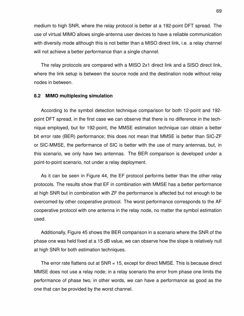
69
medium to high SNR, where the relay protocol is better at a 192-point DFT spread. The
use of virtual MIMO allows single-antenna user devices to have a reliable communication
with diversity mode although this is not better than a MISO direct link, i.e. a relay channel
will not achieve a better performance than a single channel.
The relay protocols are compared with a MISO 2x1 direct link and a SISO direct link,
where the link setup is between the source node and the destination node without relay
nodes in between.
8.2 MIMO multiplexing simulation
According to the symbol detection technique comparison for both 12-point and 192-
point DFT spread, in the first case we can observe that there is no difference in the tech-
nique employed, but for 192-point, the MMSE estimation technique can obtain a better
bit error rate (BER) performance; this does not mean that MMSE is better than SIC-ZF
or SIC-MMSE, the performance of SIC is better with the use of many antennas, but, in
this scenario, we only have two antennas. The BER comparison is developed under a
point-to-point scenario, not under a relay deployment.
As it can be seen in Figure 44, the EF protocol performs better than the other relay
protocols. The results show that EF in combination with MMSE has a better performance
at high SNR but in combination with ZF the performance is affected but not enough to be
overcomed by other cooperative protocol. The worst performance corresponds to the AF
cooperative protocol with one antenna in the relay node, no matter the symbol estimation
used.
Additionally, Figure 45 shows the BER comparison in a scenario where the SNR of the
phase one was held fixed at a 15 dB value, we can observe how the slope is relatively null
at high SNR for both estimation techniques.
The error rate flattens out at SNR = 15, except for direct MMSE. This is because direct
MMSE does not use a relay node; in a relay scenario the error from phase one limits the
performance of phase two, in other words, we can have a performance as good as the
one that can be provided by the worst channel.
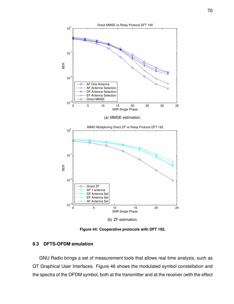
70
0 5 10 15 20 25 30 3510
−3
10−2
10−1
100
Direct MMSE vs Relay Protocol DFT 192
SNR Single Phase
BE
R
AF One Antenna
AF Antenna Selection
DF Antenna Selection
EF Antenna Selection
Direct MMSE
(a) MMSE estimation.
0 5 10 15 20 2510
−3
10−2
10−1
100
SNR Single Phase
BE
R
MIMO Multiplexing Direct ZF vs Relay Protocol DFT 192
Direct ZF
AF 1 antenna
DF Antenna Sel
EF Antenna Sel
AF Antenna Sel
(b) ZF estimation.
Figure 44: Cooperative protocols with DFT 192.
8.3 DFTS-OFDM emulation
GNU Radio brings a set of measurement tools that allows real time analysis, such as
QT Graphical User Interfaces. Figure 46 shows the modulated symbol constellation and
the spectra of the OFDM symbol, both at the transmitter and at the receiver (with the effect
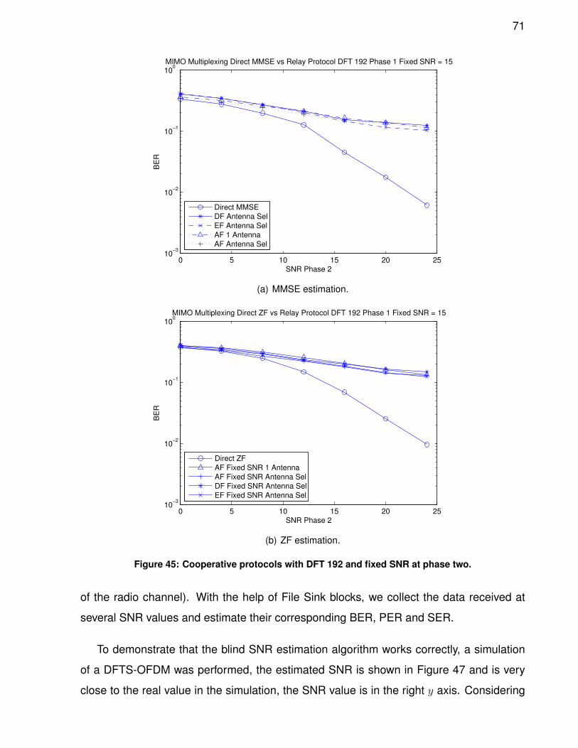
71
0 5 10 15 20 2510
−3
10−2
10−1
100
SNR Phase 2
BE
R
MIMO Multiplexing Direct MMSE vs Relay Protocol DFT 192 Phase 1 Fixed SNR = 15
Direct MMSE
DF Antenna Sel
EF Antenna Sel
AF 1 Antenna
AF Antenna Sel
(a) MMSE estimation.
0 5 10 15 20 2510
−3
10−2
10−1
100
SNR Phase 2
BE
R
MIMO Multiplexing Direct ZF vs Relay Protocol DFT 192 Phase 1 Fixed SNR = 15
Direct ZF
AF Fixed SNR 1 Antenna
AF Fixed SNR Antenna Sel
DF Fixed SNR Antenna Sel
EF Fixed SNR Antenna Sel
(b) ZF estimation.
Figure 45: Cooperative protocols with DFT 192 and fixed SNR at phase two.
of the radio channel). With the help of File Sink blocks, we collect the data received at
several SNR values and estimate their corresponding BER, PER and SER.
To demonstrate that the blind SNR estimation algorithm works correctly, a simulation
of a DFTS-OFDM was performed, the estimated SNR is shown in Figure 47 and is very
close to the real value in the simulation, the SNR value is in the right y axis. Considering
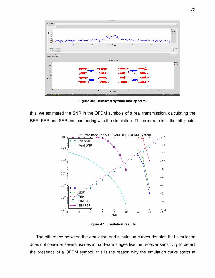
72
Figure 46: Received symbol and spectra.
this, we estimated the SNR in the OFDM symbols of a real transmission, calculating the
BER, PER and SER and comparing with the simulation. The error rate is in the left y axis.
0 2 4 6 8 10 12 14 16SNR
10-6
10-5
10-4
10-3
10-2
10-1
100 Bit Error Rate For A 16-QAM DFTS-OFDM System
BERSERPERSIM BERSIM PER
−2
0
2
4
6
8
10
12
14
16Est SNRReal SNR
Figure 47: Emulation results.
The difference between the emulation and simulation curves denotes that simulation
does not consider several issues in hardware stages like the receiver sensitivity to detect
the presence of a OFDM symbol, this is the reason why the emulation curve starts at
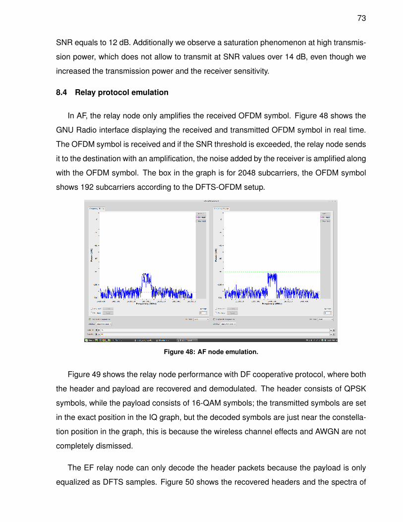
73
SNR equals to 12 dB. Additionally we observe a saturation phenomenon at high transmis-
sion power, which does not allow to transmit at SNR values over 14 dB, even though we
increased the transmission power and the receiver sensitivity.
8.4 Relay protocol emulation
In AF, the relay node only amplifies the received OFDM symbol. Figure 48 shows the
GNU Radio interface displaying the received and transmitted OFDM symbol in real time.
The OFDM symbol is received and if the SNR threshold is exceeded, the relay node sends
it to the destination with an amplification, the noise added by the receiver is amplified along
with the OFDM symbol. The box in the graph is for 2048 subcarriers, the OFDM symbol
shows 192 subcarriers according to the DFTS-OFDM setup.
Figure 48: AF node emulation.
Figure 49 shows the relay node performance with DF cooperative protocol, where both
the header and payload are recovered and demodulated. The header consists of QPSK
symbols, while the payload consists of 16-QAM symbols; the transmitted symbols are set
in the exact position in the IQ graph, but the decoded symbols are just near the constella-
tion position in the graph, this is because the wireless channel effects and AWGN are not
completely dismissed.
The EF relay node can only decode the header packets because the payload is only
equalized as DFTS samples. Figure 50 shows the recovered headers and the spectra of
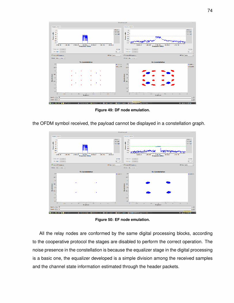
74
Figure 49: DF node emulation.
the OFDM symbol received, the payload cannot be displayed in a constellation graph.
Figure 50: EF node emulation.
All the relay nodes are conformed by the same digital processing blocks, according
to the cooperative protocol the stages are disabled to perform the correct operation. The
noise presence in the constellation is because the equalizer stage in the digital processing
is a basic one, the equalizer developed is a simple division among the received samples
and the channel state information estimated through the header packets.
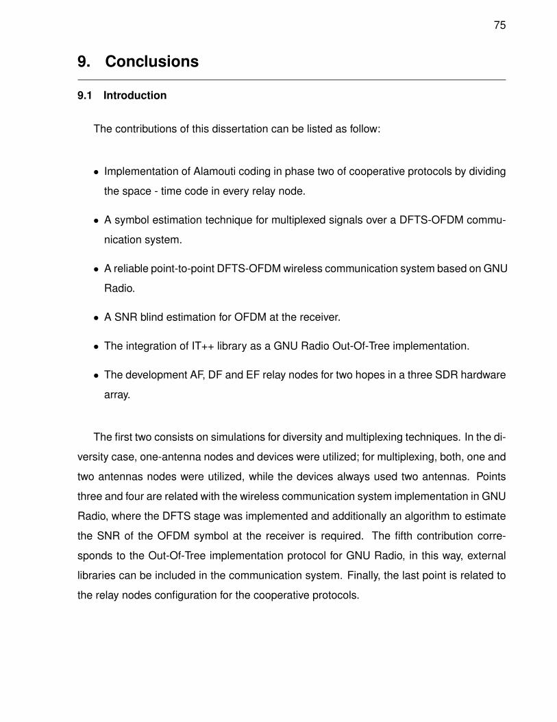
75
9. Conclusions
9.1 Introduction
The contributions of this dissertation can be listed as follow:
• Implementation of Alamouti coding in phase two of cooperative protocols by dividing
the space - time code in every relay node.
• A symbol estimation technique for multiplexed signals over a DFTS-OFDM commu-
nication system.
• A reliable point-to-point DFTS-OFDM wireless communication system based on GNU
Radio.
• A SNR blind estimation for OFDM at the receiver.
• The integration of IT++ library as a GNU Radio Out-Of-Tree implementation.
• The development AF, DF and EF relay nodes for two hopes in a three SDR hardware
array.
The first two consists on simulations for diversity and multiplexing techniques. In the di-
versity case, one-antenna nodes and devices were utilized; for multiplexing, both, one and
two antennas nodes were utilized, while the devices always used two antennas. Points
three and four are related with the wireless communication system implementation in GNU
Radio, where the DFTS stage was implemented and additionally an algorithm to estimate
the SNR of the OFDM symbol at the receiver is required. The fifth contribution corre-
sponds to the Out-Of-Tree implementation protocol for GNU Radio, in this way, external
libraries can be included in the communication system. Finally, the last point is related to
the relay nodes configuration for the cooperative protocols.
76
9.2 SFBC with cooperative protocols
Although there is not a specified relay protocol to develop the cooperative communi-
cation in any 4G, 5G and WLAN standards, all of them allow a free implementation of the
protocol. Considering this, we made a BER-based comparison among the most known
cooperative protocols, i.e. AF, DF and EF. We found that the AF protocol performs better
than the other two protocols. In order to point out the differences between a direct link
and a cooperative communication, we compared the BER performance of MISO 2x1 with
SISO direct link. We noticed that the AF protocol outperforms both DF and EF at medium
to high SNR.
AF is not a good cooperative protocol in a SISO scenario because there is no channel
compensation at phase one and the noise is sent to the destination node, contrary to DF
and EF cases where the relay node nullifies the channel effects from the phase one and
sends a new symbol to the destination.
When the Alamouti code is implemented in the relay scenario and considering that
its BER performance is better than that of a SISO system, the AF protocol has a better
performance than DF and EF. This is because in AF the Alamouti receiver mitigates the
channel effects from both phases, which is different from the DF and EF protocols, where
their respective nodes mitigate the channels effects from phase one leaving to the Alam-
outi receiver just the channel effects from phase two. In other words, in AF all the relay
channels are mitigated by the Alamouti receiver but in DF and EF the Alamouti code effi-
ciency is affected by the relay nodes leaving the second half of the relay channels to the
destination node.
More over, in accordance with information theory literature (Gallager, 1968), the av-
erage uncertainty about the input of a channel, given the channel output, can never de-
crease as we advance in a sequence of cascaded channels. As expected, the cooperative
protocols cannot perform better than their respective point-to-point version; however, this
work objective is to bring an option to single-antenna devices to perform a reliable MIMO
communication through virtual MIMO arrays by means of relay nodes.
77
9.3 MIMO with cooperative protocols
The new technologies consider new networks scenarios where the picocells presence
will be the basis of these wireless architectures, the picocells could be provided by users
in schemes like user-provided networks or centric-provided networks; the main advantage
will be the price reduction and easy installation, at the cost of involving cell-edge manage-
ment and devices with interference cancellation algorithms, as a result of the presence of
network densification.
We made a BER-based comparison among the most known cooperative protocols, i.e.
AF, DF and EF protocol. We found that EF protocol performs better than the other two
protocols, including AF with one antenna. In order to point out the differences between a
direct link and a cooperative communication, we compared the BER performance of MIMO
2x2 with MMSE direct link (SISO array). We noticed that the EF protocol outperforms AF
with antenna selection, AF with one antenna and DF at medium to high SNR.
The MIMO simulation presents a very similar result at SISO performance with coop-
erative protocols, with the difference that EF is a better protocol than DF protocol. Both
network scenarios variation presented for AF were considered with single-antennas de-
vices as relay nodes, this is a cheaper relay scenario but not a good option due the BER
performance; in the two-antenna relay case, we could consider a waste when disabling
an antenna at the phase two, but for a fair comparison with the MIMO 2x2 direct link, a
cooperative virtual MIMO 2x2 array was configured in the second phase. However, this
goal of this work is to bring an option to single-antenna devices (located close to the edge
of a cell) to perform a reliable MIMO communication trough virtual MIMO arrays by means
of relay nodes; this would increase the cell coverage.
The symbol estimation technique is a central part in the relay scenario BER perfor-
mance. Leaving the destination node the task of mitigating all channels effects could be
a complex task, mainly due to the channel estimation than to the symbol estimation, the
channel estimation in the AF with antenna selection scenarios considers a sum of both
channels in phase one which is retransmitted at phase two by the relay node, this way the
destination node needs to estimate six channels. For AF with one antenna the complexity
78
is larger due to the mixed symbols received in the relay nodes at phase one, more than to
the channel effects; the destination node recovers a mixed symbol from the relay nodes
and estimates the original symbol from this signal mixture.
9.4 DFTS-OFDM
The development of a DFTS-OFDM system in GNU Radio involves three main pro-
cesses: synchronization, channel estimation and transmission. In simulation environ-
ments the synchronization and channel estimation is not usually considered, the focus is
on bit error rate or channel capacity evaluation. The emulation requires both synchroniza-
tion and channel estimation to perform a sucessfull transmission allowing the research in
many stages and obtaining numerical results in real environments.
GNU Radio includes a good equalizer in the time domain, but a DFTS-OFDM system
requires a frequency domain equalizer, this is because the simple DFE equalizer can
estimate the digital symbol transmitted. The use of frequency domain equalizers allow to
perform a better channel effect cancellation and a more accurate symbol estimation; an
alternative would be to customize the simple DFE equalizer, such that includes the DFTS
stage in the symbol estimation loop-back, this way the symbol estimation will be performed
over digital samples and not over the DFT samples. In the emulation, a simple division of
the received signal by the estimated channel was performed; the main problem is that the
received symbol does not belong to a known modulation symbol constellation set but a
DFT representation of it. The frequency domain equalizers can be included as classes in
GNU Radio, this way, the equalizer function can be deployed without a new digital signal
processing block and can profit the actual structure of the GNU radio function classes.
9.5 DFTS-OFDM relay
The emulation of a cooperative protocol without diversity or multiplexing is not very
helpful for the source node, but it is applicable without many complications and allows
to find the weakness in relay channels. As more relay nodes are added to the network
scenario, the channel capacity of the system is increased and both error rate and bit
rate show improvements, therefore, the development of virtual MIMO scenarios with relay
nodes based on GNU Radio could be possible.
79
At the receiver in diversity mode, the equalizer must be disabled because the Alamouti
decoder requires the channel state information to estimate the symbol, at the same time,it
is important to note that the header packets will not be encoded by the Alamouti code,
because these packets are used in the first stage to estimate the channel and verify that
the information is correct.
9.6 Further work
The new generations of wireless communications are actually oriented to DFTS-OFDM,
massive MIMO, device-to-device communication and relay nodes for network densifica-
tion; otherwise it is also considered to work in millimeter waves around 30 and 50 GHz.
This platform will allow to work in these research topics with less modifications in the
hardware leaving all the customization to the software. Techniques like cognitive radio
are highly related with software radio, because the transmitter needs to be tuned to an
available frequency.
On the other hand, the development of a DFTS-OFDM testbed via GNU Radio and
USRP allows the possibility to deploy and test new techniques in PHY layer, therefore,
the research will not give theoretical results in simulated wireless channels but from real
wireless channels. Although all the PHY layer processes are performed by a computer
and the USRP testbed is only the frontend for the wireless link, to include another layer
like MAC or NETWORK will depend on the programmer skills since the USRP testbed
does not interfere with those layers.
We have observed that the receiver cannot work at SNRs higher than 14 dB, since even
though we increased the TX power, the noise at the RX increased as well, maintaining the
SNR at an almost constant value. We propose two possible solutions to this problem; the
first one is to modify the Schmidl and Cox block (which detects the signal). The second
solution may be to include a digital signal processor block before the Schmidl and Cox, so
the noise floor would be kept to a minimum level.
The next step is to develop a block code for achieving diversity or a multiplexing tech-
nique with SDR. For the diversity mode, the development of block codes like Alamouti can
be performed through mathematical and stream operators signal processing blocks, but
80
this results in a fixed size block code which could not be customized. The development
of a signal processing block that performs in any kind of block code like S-T, S-F or S-T-F
could make it easy to implement and test in the emulation stage. This signal process-
ing block would generate the data flows required for the specific code and the required
number of antennas of the corresponding MIMO array.
In a similar way, the development of a signal processing block for multiplexing could be
deployed via software, although for MIMO multiplexing it only requires a data flow splitter
to send data to the MIMO array, it will be pertinent to add a signal processing block for
the precoding stage. The transmitter is basically simpler than the receiver because a
symbol estimation is needed for demultiplexing the received signal, but because there
are several techniques that can perform these processes (like ZF, MMSE, SIC-ZF or SIC-
MMSE among others), it will be considered a general signal processing block where the
symbol estimation technique can be selected and by means of functions or classes will
allow the development of new algorithms.
In addition to the frequency domain equalizer class for DFTS-OFDM systems, signal
processing block for block codes and precoding for diversity and multiplexing mode re-
spectively, the development of relay scenarios or MIMO array scenarios will require to
obtain the channel state information of the MIMO channels. Actually GNU Radio includes
the channel state estimation for one-antenna device, so that it will be necessary to in-
clude a couple of synchronization words by antenna and specify the way how the header
data will be transmitted; either by only one antenna or having each antenna transmitting a
different header.
81
List of bibliographical referencesAbirami, M., Hariharan, V., Sruthi, M., Gandhiraj, R., and Soman, K. (2013). Exploiting
gnu radio and usrp: an economical test bed for real time communication systems. En:Computing, Communications and Networking Technologies (ICCCNT), 2013 Fourth In-ternational Conference on. IEEE, pp. 1–6.
Akyildiz, I. F., Gutierrez-Estevez, D. M., and Reyes, E. C. (2010). The evolution to 4gcellular systems: Lte-advanced. Physical Communication, 3(4): 217–244.
Alamouti, S. M. (1998). A simple transmit diversity technique for wireless communications.Selected Areas in Communications, IEEE Journal on, 16(8): 1451–1458.
Alshaalan, F., Alshebeili, S., Adinoyi, A., et al. (2010). On the performance of mobile wimaxsystem: Measurement and propagation studies. Int’l J. of Communications, Networkand System Sciences, 3(11): 863.
Barros, A., Lenzi, K., Meloni, L., Barbin, S., et al. (2012). Introduction to the software-defined radio approach. Latin America Transactions, IEEE (Revista IEEE AmericaLatina), 10(1): 1156–1161.
Beazley, D. M. et al. (1996). Swig: An easy to use tool for integrating scripting languageswith c and c++. En: Proceedings of the 4th USENIX Tcl/Tk workshop. pp. 129–139.
Berardinelli, G., Temino, L. A. M. R. D., Frattasi, S., Rahman, M. I., and Mogensen, P.(2008). Ofdma vs. sc-fdma: performance comparison in local area imt-a scenarios.Wireless Communications, IEEE , 15(5): 64–72.
Bhushan, N., Li, J., Malladi, D., Gilmore, R., Brenner, D., Damnjanovic, A., Sukhavasi,R., Patel, C., and Geirhofer, S. (2014). Network densification: the dominant theme forwireless evolution into 5g. Communications Magazine, IEEE , 52(2): 82–89.
Boeglen, H. (2007). It++ library for numerical communications simulations.
Borgmann, M. and Bolcskei, H. (2005). Noncoherent space-frequency coded mimo-ofdm.Selected Areas in Communications, IEEE Journal on, 23(9): 1799–1810.
Capozzi, F., Piro, G., Grieco, L. A., Boggia, G., and Camarda, P. (2013). Downlink packetscheduling in lte cellular networks: Key design issues and a survey. CommunicationsSurveys & Tutorials, IEEE , 15(2): 678–700.
Ciochina, C. and Sari, H. (2010). A review of ofdma and single-carrier fdma. En: WirelessConference (EW), 2010 European. IEEE, pp. 706–710.
Cover, T. M. and Gamal, A. E. (1979). Capacity theorems for the relay channel. InformationTheory, IEEE Transactions on, 25(5): 572–584.
Dhar, R., George, G., Malani, A., and Steenkiste, P. (2006). Supporting integrated mac andphy software development for the usrp sdr. En: Networking Technologies for SoftwareDefined Radio Networks, 2006. SDR’06.1 st IEEE Workshop on. IEEE, pp. 68–77.
Ettus, M. (2005). Usrp user’s and developer’s guide. Ettus Research LLC.
82
Fazel, F. and Jafarkhani, H. (2008). Quasi-orthogonal space-frequency and space-time-frequency block codes for mimo ofdm channels. Wireless Communications, IEEE Trans-actions on, 7(1): 184–192.
Foschini, G. J. (1996). Layered space-time architecture for wireless communication ina fading environment when using multi-element antennas. Bell labs technical journal ,1(2): 41–59.
Gallager, R. G. (1968). Information theory and reliable communication, Vol. 2. Springer.
Ghosh, A., Ratasuk, R., Mondal, B., Mangalvedhe, N., and Thomas, T. (2010). Lte-advanced: next-generation wireless broadband technology [invited paper]. WirelessCommunications, IEEE , 17(3): 10–22.
Golden, G., Foschini, C., Valenzuela, R. A., and Wolniansky, P. (1999). Detection algo-rithm and initial laboratory results using v-blast space-time communication architecture.Electronics letters, 35(1): 14–16.
Goldsmith, A. (2005). Wireless communications. Cambridge university press.
Goldsmith, A., Jafar, S., Jindal, N., and Vishwanath, S. (2003). Capacity limits of mimochannels. Selected Areas in Communications, IEEE Journal on, 21(5): 684–702.
Gonzalez, C. R. A., Dietrich, C. B., Sayed, S., Volos, H., Gaeddert, J. D., Robert, P. M.,Reed, J. H., Kragh, F. E., et al. (2009). Open-source sca-based core framework andrapid development tools enable software-defined radio education and research. Com-munications Magazine, IEEE , 47(10): 48–55.
Hassan, E. S. (2012). Energy-efficient hybrid opportunistic cooperative protocol for single-carrier frequency division multiple access-based networks. Iet Communications, 6(16):2602–2612.
Himsoon, T., Su, W., and Liu, K. (2006). Single-block differential transmit scheme forbroadband wireless mimo-ofdm systems. Signal Processing, IEEE Transactions on,54(9): 3305–3314.
Hochwald, B. and Sweldens, W. (2000). Differential unitary space-time modulation. Com-munications, IEEE Transactions on, 48(12): 2041–2052.
Hong, Z., Thibault, L., and Zhang, L. (2006). Differential space-frequency trellis codes.Wireless Communications, IEEE Transactions on, 5(10): 2664–2668.
Hoymann, C., Chen, W., Montojo, J., Golitschek, A., Koutsimanis, C., and Shen, X. (2012).Relaying operation in 3gpp lte: challenges and solutions. Communications Magazine,IEEE , 50(2): 156–162.
Hughes, B. (2000). Differential space-time modulation. Information Theory, IEEE Trans-actions on, 46(7): 2567–2578.
Iosifidis, G., Gao, L., Huang, J., and Tassiulas, L. (2014). Incentive mechanisms for user-provided networks. Communications Magazine, IEEE , 52(9): 20–27.
83
Jafarkhani, H. (2005). Space-time coding: theory and practice. Cambridge universitypress.
Jafarkhani, H. and Seshadri, N. (2003). Super-orthogonal space-time trellis codes. Infor-mation Theory, IEEE Transactions on, 49(4): 937–950.
Kadhim, M. A. and Ismail, W. (2011). Implementation transmitter diversity with tomlinson-harashima precoding for wimax ieee802. 16d ostbc-ofdm baseband transceiver on amulti-core software defined radio platform. World Applied Sciences Journal , 12(9):1482–1491.
Kindratenko, V., Pant, M., and Pointer, D. (2005). Deploying the olsr protocol on a networkusing sdr as the physical layer. Reporte tecnico, NCASSR Technical Report, UCLA.
Kishiyama, Y., Benjebbour, A., Nakamura, T., and Ishii, H. (2013). Future steps of lte-a:evolution toward integration of local area and wide area systems. Wireless Communi-cations, IEEE , 20(1): 12–18.
Koyuncu, E., Jing, Y., and Jafarkhani, H. (2008). Distributed beamforming in wireless relaynetworks with quantized feedback. Selected Areas in Communications, IEEE Journalon, 26(8): 1429–1439.
Lai, H.-Q. and Liu, K. (2011). Space-time network coding. Signal Processing, IEEETransactions on, 59(4): 1706–1718.
Laneman, J. N. and Wornell, G. W. (2003). Distributed space-time-coded protocols forexploiting cooperative diversity in wireless networks. Information Theory, IEEE Trans-actions on, 49(10): 2415–2425.
Larsson, E., Edfors, O., Tufvesson, F., and Marzetta, T. (2014). Massive mimo for nextgeneration wireless systems. Communications Magazine, IEEE , 52(2): 186–195.
Lee, K. F. and Williams, D. B. (2000). A space-frequency transmitter diversity techniquefor ofdm systems. En: Global Telecommunications Conference, 2000. GLOBECOM’00.IEEE . IEEE, Vol. 3, pp. 1473–1477.
Li, Q., Li, K., and Teh, K. (2008). Noncoherent space-frequency codes for broadbandmimo systems over frequency-selective fading channels. En: Vehicular TechnologyConference, 2008. VTC Spring 2008. IEEE , May. pp. 554–558.
Li, Q., Li, G., Lee, W., Lee, M.-i., Mazzarese, D., Clerckx, B., and Li, Z. (2010). Mimotechniques in wimax and lte: a feature overview. Communications Magazine, IEEE ,48(5): 86–92.
Li, R., Bai, Z., and Kwak, K. (2009). Space frequency codes based amplify-and-forwardcooperative system. En: Communications and Information Technology, 2009. ISCIT2009. 9th International Symposium on. IEEE, pp. 1185–1188.
Li, Y. (2010). Blind snr estimation of ofdm signals. En: 2010 International Conference onMicrowave and Millimeter Wave Technology . pp. 1792–1796.
84
Ma, Q., Tepedelenlioglu, C., and Liu, Z. (2005). Differential space-time-frequency codedofdm with maximum multipath diversity. Wireless Communications, IEEE Transactionson, 4(5): 2232–2243.
Maeder, A. and Zein, N. (2010). Ofdma in the field: current and future challenges. ACMSIGCOMM Computer Communication Review , 40(5): 71–76.
Mandke, K., Choi, S.-H., Kim, G., Grant, R., Daniels, R. C., Kim, W., Heath Jr, R. W.,and Nettles, S. M. (2007). Early results on hydra: A flexible mac/phy multihop testbed.En: Vehicular Technology Conference, 2007. VTC2007-Spring. IEEE 65th. IEEE, pp.1896–1900.
Marwanto, A., Sarijari, M. A., Fisal, N., Yusof, S. K. S., Rashid, R., et al. (2009). Ex-perimental study of ofdm implementation utilizing gnu radio and usrp-sdr. En: Com-munications (MICC), 2009 IEEE 9th Malaysia International Conference on. IEEE, pp.132–135.
Mitola, J. (1995). The software radio architecture. Communications Magazine, IEEE ,33(5): 26–38.
Mitola III, J. (1993). Software radios: Survey, critical evaluation and future directions.Aerospace and Electronic Systems Magazine, IEEE , 8(4): 25–36.
Myung, H. G. (2007). Introduction to single carrier fdma. En: Proceedings of the 15thEuropean Signal Processing Conference (EUSIPCO’07). Citeseer, pp. 2144–2148.
Myung, H. G., Lim, J., and Goodman, D. J. (2006a). Peak-to-average power ratio ofsingle carrier fdma signals with pulse shaping. En: Personal, Indoor and Mobile RadioCommunications, 2006 IEEE 17th International Symposium on. IEEE, pp. 1–5.
Myung, H. G., Lim, J., and Goodman, D. J. (2006b). Single carrier fdma for uplink wirelesstransmission. Vehicular Technology Magazine, IEEE , 1(3): 30–38.
Nagaraj, S., Garg, S., Liang, F., Yang, W., Mangalvedhe, N., Haug, J., and Pradap, K.(2009). Lab performance analysis of a 4g lte prototype. En: Wireless Communicationsand Networking Conference, 2009. WCNC 2009. IEEE . IEEE, pp. 1–6.
Natalizio, E., Loscri, V., Aloi, G., Paoli, N., and Barbaro, N. (2010). The practical experi-ence of implementing a gsm bts through open software/hardware. En: Applied Sciencesin Biomedical and Communication Technologies (ISABEL), 2010 3rd International Sym-posium on. IEEE, pp. 1–5.
Noune, M. and Nix, A. (2009). Frequency-domain precoding for single carrier frequency-division multiple access. Communications Magazine, IEEE , 47(6): 68–74.
Nunes, B., Santos, M., de Oliveira, B. T., Margi, C. B., Obraczka, K., Turletti, T., et al.(2014). Software-defined-networking-enabled capacity sharing in user-centric networks.Communications Magazine, IEEE , 52(9): 28–36.
Parikh, J. and Basu, A. (2011). Lte advanced: The 4g mobile broadband technology.spectrum, 5(2.5): 30.
85
Parkvall, S. and Astely, D. (2009). The evolution of lte towards imt-advanced. Journal ofcommunications, 4(3): 146–154.
Priyanto, B. E., Codina, H., Rene, S., SØrensen, T. B., and Mogensen, P. (2007). Initialperformance evaluation of dft-spread ofdm based sc-fdma for utra lte uplink. En: Vehic-ular Technology Conference, 2007. VTC2007-Spring. IEEE 65th. IEEE, pp. 3175–3179.
Reddy, B. and Lakshmi, B. (2014). Adaptive modulation and coding for mobile-wimax us-ing sdr in gnu radio. En: Circuits, Systems, Communication and Information TechnologyApplications (CSCITA), 2014 International Conference on. IEEE, pp. 173–178.
Rodriguez, V. and Sanchez, J. (2014). Empowering software radio: It++ as a gnu radioout-of-tree implementation. Latin America Transactions, IEEE (Revista IEEE AmericaLatina), 12(2): 269–276.
Rondeau, T. W. (2015). On the gnu radio ecosystem. Opportunistic Spectrum Sharingand White Space Access: The Practical Reality , pp. 25–48.
Rong, L., Elayoubi, S. E., and Haddada, O. B. (2010). Impact of relays on lte-advancedperformance. En: Communications (ICC), 2010 IEEE International Conference on.IEEE, pp. 1–6.
Rusek, F., Persson, D., Lau, B. K., Larsson, E., Marzetta, T., Edfors, O., and Tufvesson, F.(2013). Scaling up mimo: Opportunities and challenges with very large arrays. SignalProcessing Magazine, IEEE , 30(1): 40–60.
Saravanan, M. and Ravi, S. (2011). Performance analysis of different spreading codesin cdma system environment for multi-user adaptive sdr environment. IJCSNS Interna-tional Journal of Computer Science and Network Security , 11(7): 28–37.
Schmidl, T. M. and Cox, D. C. (1997). Robust frequency and timing synchronization forofdm. Communications, IEEE Transactions on, 45(12): 1613–1621.
Schroeder, W. J., Ibanez, L., and Martin, K. M. (2004). Software process: the key todeveloping robust, reusable and maintainable open-source software. En: BiomedicalImaging: Nano to Macro, 2004. IEEE International Symposium on. IEEE, pp. 648–651.
Sendonaris, A., Erkip, E., and Aazhang, B. (2003). User cooperation diversity. part i.system description. Communications, IEEE Transactions on, 51(11): 1927–1938.
Sesia, S., Toufik, I., and Baker, M. (2009). LTE: the UMTS long term evolution. WileyOnline Library.
Su, W., Sadek, A. K., and Liu, K. R. (2008). Cooperative communication protocols in wire-less networks: performance analysis and optimum power allocation. Wireless PersonalCommunications, 44(2): 181–217.
Swindlehurst, A. L., Ayanoglu, E., Heydari, P., and Capolino, F. (2014). Millimeter-wavemassive mimo: the next wireless revolution. IEEE Communications Magazine, 52(9):56–62.
86
Tao, M. (2006). High rate trellis coded differential unitary space-time modulation via superunitarity. Wireless Communications, IEEE Transactions on, 5(12): 3350–3354.
Tarokh, V. and Jafarkhani, H. (2000). A differential detection scheme for transmit diversity.Selected Areas in Communications, IEEE Journal on, 18(7): 1169–1174.
Tarokh, V., Jafarkhani, H., and Calderbank, A. (1999). Space-time block codes from or-thogonal designs. Information Theory, IEEE Transactions on, 45(5): 1456–1467.
Temi, D., Ruiz, L. A. M., Berardinelli, G., Frattasi, S., Pajukoski, K., and Mogensen, P.(2009). Single-user mimo for lte-a uplink: performance evaluation of ofdma vs. sc-fdma.En: Radio and Wireless Symposium, 2009. RWS’09. IEEE . IEEE, pp. 304–307.
Teodoro, S., Silva, A., Gil, J. M., and Gameiro, A. (2009a). Distributed space-frequencyblock coding for a 2-antenna relay in downlink ofdm systems. En: Communications andInformation Technology, 2009. ISCIT 2009. 9th International Symposium on. IEEE, pp.853–858.
Teodoro, S., Silva, A., Gil, J. M., and Gameiro, A. (2009b). Virtual mimo schemes for down-link space-frequency coding ofdm systems. En: Personal, Indoor and Mobile RadioCommunications, 2009 IEEE 20th International Symposium on. IEEE, pp. 1322–1326.
Tucker, D. C., Tagliarini, G., et al. (2009). Prototyping with gnu radio and the usrp-whereto begin. En: Southeastcon, 2009. SOUTHEASTCON’09. IEEE . IEEE, pp. 50–54.
Wang, C.-X., Hong, X., Ge, X., Cheng, X., Zhang, G., and Thompson, J. (2010). Co-operative mimo channel models: A survey. Communications Magazine, IEEE , 48(2):80–87.
Wang, H., You, X., Jiang, B., and Gao, X. (2008). Performance analysis of frequencydomain equalization in sc-fdma systems. En: Communications, 2008. ICC’08. IEEEInternational Conference on. IEEE, pp. 4342–4347.
Wolniansky, P. W., Foschini, G. J., Golden, G., Valenzuela, R., et al. (1998). V-blast: Anarchitecture for realizing very high data rates over the rich-scattering wireless channel.En: Signals, Systems, and Electronics, 1998. ISSSE 98. 1998 URSI International Sym-posium on. IEEE, pp. 295–300.
Wu, D., Eilert, J., and Liu, D. (2011). Implementation of a high-speed mimo soft-outputsymbol detector for software defined radio. Journal of Signal Processing Systems,63(1): 27–37.
Yellin, D. and Weinstein, E. (1994). Criteria for multichannel signal separation. SignalProcessing, IEEE Transactions on, 42(8): 2158–2168.
Yuan, G., Zhang, X., Wang, W., and Yang, Y. (2010). Carrier aggregation for lte-advancedmobile communication systems. Communications Magazine, IEEE , 48(2): 88–93.
Zhang, C., Wang, Z., Yang, Z., Wang, J., and Song, J. (2010). Frequency domain decisionfeedback equalization for uplink sc-fdma. Broadcasting, IEEE Transactions on, 56(2):253–257.
87
Zhang, S., Yang, F., and Tang, L. (2015). Network-coding-based multisource multirelayldpc-coded cooperative mimo. Trans. Emerg. Telecommun. Technol., 26(3): 491–502.
Zheng, K., Huang, L., Li, G., Cao, H., Wang, W., and Dohler, M. (2008). Beyond 3gevolution. Vehicular Technology Magazine, IEEE , 3(2): 30–36.
Zhu, Y. and Jafarkhani, H. (2005). Differential modulation based on quasi-orthogonalcodes. Wireless Communications, IEEE Transactions on, 4(6): 3005–3017.
Zhu, Y. and Jafarkhani, H. (2006). Differential super-orthogonal space-time trellis codes.Wireless Communications, IEEE Transactions on, 5(12): 3634–3643.
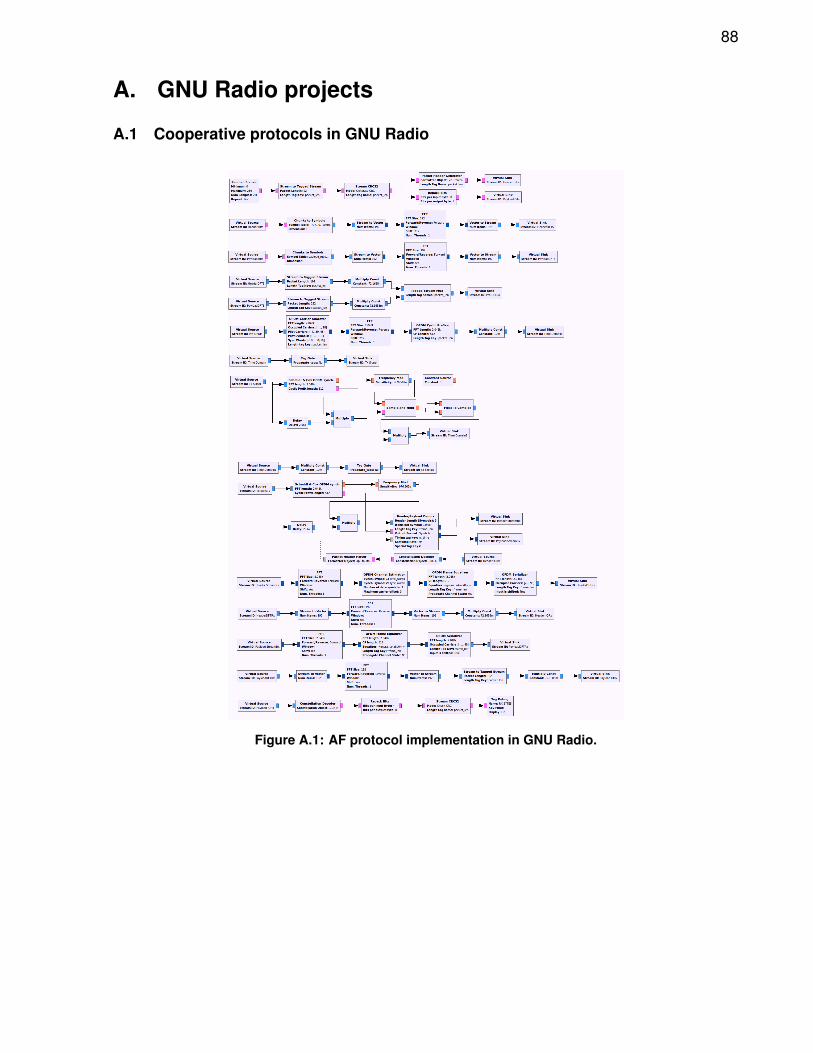
88
A. GNU Radio projects
A.1 Cooperative protocols in GNU Radio
Figure A.1: AF protocol implementation in GNU Radio.
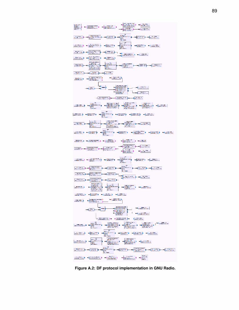
89
Figure A.2: DF protocol implementation in GNU Radio.
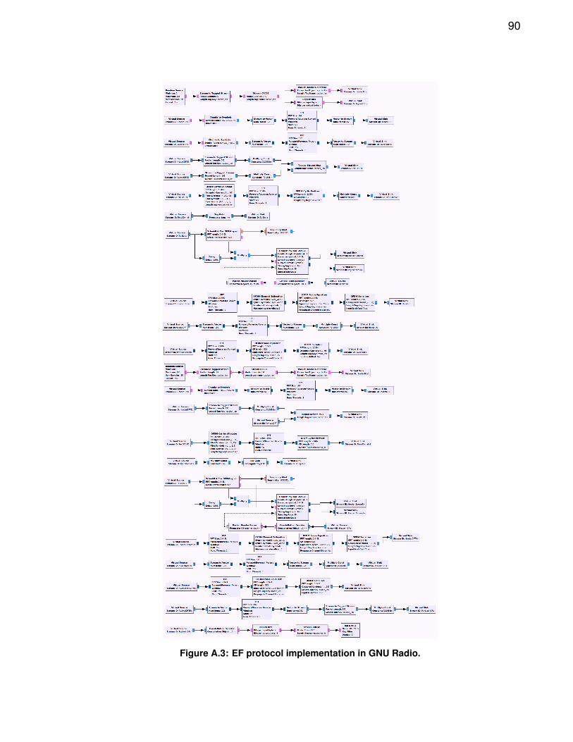
90
Figure A.3: EF protocol implementation in GNU Radio.


![Borges en el Hogar - Bibliotecabiblio3.url.edu.gt/Libros/2011/borges/8.pdf · ... de Arthur Palmer Hudson [LN] ... A Trojan Ending, de Laura Riding ... "Diario de Francis Jammes en](https://img.pdfslide.es/doc/110x75/5c22c11d09d3f280688c6163/borges-en-el-hogar-de-arthur-palmer-hudson-ln-a-trojan-ending-de.jpg)


![Criptografía RSA: fundamentos y desarrollo fileTrabajo fin de Grado en Matemáticas Universidad de Zaragoza. Abstract ... [14]. Other fascinating techniques are the Zero Knowledge](https://img.pdfslide.es/doc/110x75/5bbcf8a709d3f240128c7790/criptografia-rsa-fundamentos-y-desarrollo-n-de-grado-en-matematicas-universidad.jpg)