Embed Size (px)
Citation preview
7/24/2019 DATA AIRE
http://slidepdf.com/reader/full/data-aire 1/76
1
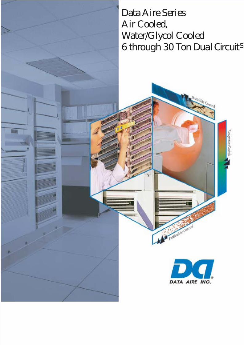
Data Aire SeriesAir Cooled,Water/Glycol Cooled6 through 30 Ton Dual Circ
7/24/2019 DATA AIRE
http://slidepdf.com/reader/full/data-aire 2/76
2
Data Aire®
… the pioneer and builder of the
most complete line of
precision cooling equipment
Data Aire’s first precision cooling system was developed by data processing engineers who sought
optimum environmental conditions for early computers. It was clear that “people comfort” air
conditioning system were unable to meet the environmental requirements of computers and data
processing equipment. Precision environmental control equipment with high sensible cooling ratios was
a necessity. Problems with paper sticking , head crash, and static electricity were eliminated. Humidity
fluctuation were controlled saving possible electrical and mechanical failures and more importantly –
Downtime. Data Aire’s innovative response to the challenge of eliminating problems within the
computer room environment was the start of wide use precision cooling.
As in the past, Data Aire is meeting today’s challenge of not only the computer room but also the ever
expanding telecommunications industry where precision cooling is vital to our everyday
communications. Telecommunication equipment requires a controlled environment with clean and
properly distributed air. As in the computer room, the environment must be precisely controlled – 24hour a day, 365 days a year.
Data Aire produces solutions. We have offered environmental control solutions to meet specific needs
in the smallest of places and in areas of thousands of square feet. We are prepared to assist you, your in-
house engineering department, consulting engineer, or construction department in defining the proper
solutions and bringing them to a predefined outcome.
Data Aire is committed to being the supplier of choice for environmental process cooling with flexibility,
reliability, and expertise required to meet our customer’s needs. To be successful, it is essential to be
creative and use our resources to their fullest capabilities. The Data Aire goal is to benefit the
employees, partners, and most of all – our customers with honesty and integrity.
Data Aire Delivers!
7/24/2019 DATA AIRE
http://slidepdf.com/reader/full/data-aire 3/76
3
TABLE OF CONTENTS
DATA AIRE DX SERIES
DIRECT EXPANSION UNITS
AIR COOLED, WATER COOLED, GLYCOL COOLED
(Seperate brochure for Chilled Water Cooled units.)
Data Aire, Inc. reserves the right to make design changes for the purpose of
product improvement or to withdraw any design without notice.
Design Features ................................................................................................ 5
System Controls ............................................................................................... 8Options ........................................................................................................... 12
Model Number Identification ......................................................................... 16
Performance Data
Air Cooled .................................................................................... 18
Water Cooled ................................................................................ 24
Glycol Cooled ............................................................................... 30
Energy Saver ................................................................................. 36
Auxiliary Chilled Water ................................................................. 38
Dimensional and Component Drawings
6, 8, and 10 ton ............................................................................. 40
13 ton ............................................................................................ 44
16, 20, and 26 ton ......................................................................... 48
30 ton ............................................................................................ 50
Plenum and Floorstand ................................................................. 56
Heat Exchangers ........................................................................... 57
Standard Condenser Electrical Data .............................................................. 63
Dimensional and Weight Information ............................................................. 64Guide Specifications ....................................................................................... 66
7/24/2019 DATA AIRE
http://slidepdf.com/reader/full/data-aire 4/76
4
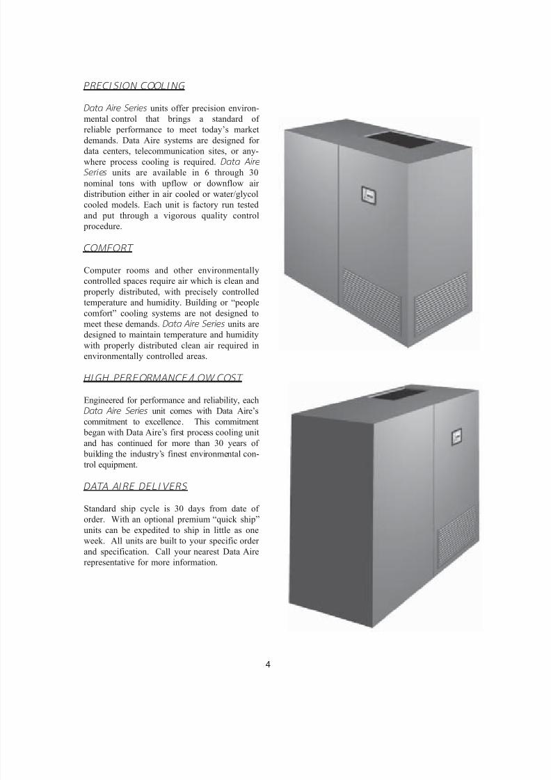
PRECISION COOLING
Data A ir e Series units offer precision environ-
mental control that brings a standard of
reliable performance to meet today’s market
demands. Data Aire systems are designed for
data centers, telecommunication sites, or any-
where process cooling is required. Data Air e
Series units are available in 6 through 30
nominal tons with upflow or downflow air
distribution either in air cooled or water/glycol
cooled models. Each unit is factory run tested
and put through a vigorous quality control
procedure.
COMFORT
Computer rooms and other environmentallycontrolled spaces require air which is clean and
properly distributed, with precisely controlled
temperature and humidity. Building or “people
comfort” cooling systems are not designed to
meet these demands. Data Ai re Seri es units are
designed to maintain temperature and humidity
with properly distributed clean air required in
environmentally controlled areas.
HI GH PERFORMANCE/LOW COST
Engineered for performance and reliability, each
Data Ai re Seri es unit comes with Data Aire’scommitment to excellence. This commitment
began with Data Aire’s first process cooling unit
and has continued for more than 30 years of
building the industry’s finest environmental con-
trol equipment.
DATA AIRE DELI VERS
Standard ship cycle is 30 days from date of
order. With an optional premium “quick ship”
units can be expedited to ship in little as one
week. All units are built to your specific order
and specification. Call your nearest Data Aire
representative for more information.
7/24/2019 DATA AIRE
http://slidepdf.com/reader/full/data-aire 5/76
5
FRAME/CABINET
Units are constructed with heliarc welded
tubular steel frames. The tubular construc-
tion provides for maximum strength and ease of
access. Side and front panels can be easilyremoved with quarter-turn fasteners allow-
ing full access to all unit components. All
panels include 1 inch thick, 11/2 pound density
insulation for protection and sound attenuation.
COIL SECTION
Designed for draw through application, the
computer selected dual circuited A-frame coil
has an interwoven surface that increases unit
efficiency at low load conditions. Air is drawn
through both circuits of the coil at low velocity providing effective surface exposure with
minimum turbulence. Air bypass is provided to
prevent saturated air from being introduced into
the controlled space. The coil sits in a stainless
steel drain pan.
FAN SECTION
The centrifugal, forward curved, double width,
double inlet blower configuration is engineered
for quiet reliable operation. The dual belt driven
variable pitch drive section provides adjustable
air flow capability to match the load require-ments of the controlled space. The draw through
design insures even air distribution across the coil,
low internal cabinet pressure losses and static
sealing of the filter section. Motors are mounted
on an adjustable slide base and have internal
overload protection.
FI LTER SECTION
Units are provided with 4 inch deep, 30%
efficient (based on ASHRAE Std. 52-76),
pleated filters. The filter section is accessible
from the top or side on downflow units and the
right hand side on upflow units.
REHEAT
Three stage electric reheat is standard. Low-
watt density, finned, tubular sheathed coils are
constructed of stainless steel and provide
ample capacity to maintain room dry bulbconditions during dehumidification. Low-watt
density coils eliminate ionization associated
with open air electric resistance heating.
HUMIDIFICATION
Data Ai re Seri es units include an electric steam
generator humidifier with “quick change” dis-
posable cylinders and auto-flush cycle. The
steam generator humidifier with its patented
control system optimizes cylinder life and
energy efficiency by concentrating incoming wa-ter to a predetermined conductivity much higher
than that of any entering water. The control
system continuously monitors the conductivity
in the cylinder through its electronics which
allows water to be flushed as often as is neces-
sary to maintain the capacity at this design
conductivity. The high design conductivity
results in a minimum flushing of heated water
which saves energy. The humidifier is de-
signed to allow all units at any voltage to
produce full rated steam output capacity at an
optimum low water level based on this design
conductivity.
DESIGN FEATURES
7/24/2019 DATA AIRE
http://slidepdf.com/reader/full/data-aire 6/76
6
REFRIGERATION CIRCUITS
Dual refrigeration circuits include high efficiency hermetic scroll type compressors. Scroll compressors
represent new yet proven compressor technology. Scroll compressors offer a combination of reliability,
performance, and efficiency. System noise is inherently quieter with scroll compressors.
Scroll compressors offer:
Simplicity - Fewer parts. Two components, a fixed scroll and orbiting scroll, replace approximately 15
parts required to do the same work.
Improved Starting Abili ty - With the scroll design the internal compression components always start
unloaded even if the system pressures are not balanced. Since internal compressor pressures are always
balanced at start-up, low voltage characteristics are excellent for scroll compressors.
Energy Efficiency - Scroll compressors are at least 10% more efficient than reciprocating type
compressors.
The suction and discharge processes of a scroll compressor are physically separated. This reduces heat
transfer between the suction and discharge gas. In a piston type compressor the cylinder is exposed to
both suction and discharge gas. This results in high heat transfer reducing the compressor efficiency.
Scroll compressor compression and discharge processes are very smooth. Gas is compressed in
approximately 11/2 revolutions compared to less than 1/2 revolution for a piston.
Scrolls require no valves. Piston compressors require both suction and discharge valves. No valves, no
valve losses.
Durability - Significant design effort and system cost are required to protect piston compressors from
slugging and debris. Scroll compressors are designed to be more tolerant of both liquid and debris.
Reliability - Scrolls contain fewer moving parts resulting in greater reliability. Proven performance
means fewer maintenance calls for field personnel.
Lower Sound - Systems properly designed with scroll compressors will be inherently quieter. On
average, the compressor is up to 5 decibels quieter. (Sound characteristics of a scroll compressor are
different than that of a reciprocating compressor. These do not effect system performance or reliability)
These durable, heavy duty compressors have no gaskets or seals, eliminating the possibility of refrigerant
or oil leaking into the controlled space or environment. Each refrigeration circuit includes built-in
compressor overload protection, crankcase heater, filter drier, sight glass, adjustable expansion valve with
external equalizer, low pressure override timer (air cooled units), manual reset high pressure control, and
anti-short cycle timer.
Water/glycol cooled units include counterflow condensers sized to provide the required capacity for heat
rejection with minimum water/glycol flow and total pressure drop. Head pressure regulating valvescontrol the condensing temperature and maintain required capacity at various water/glycol flow rates and
temperatures.
7/24/2019 DATA AIRE
http://slidepdf.com/reader/full/data-aire 7/76
7
REFRIGERATION CIRCUITS, cont inued
Ai r Cooled with Remote Outdoor A ir Cooled
Condenser
A wide range of outdoor condensers are avail-
able with vertical air discharge. Condensers
manufactured by Data Aire are sized to meet therequired heat rejection and ambient conditions.
The industrial duty condenser design includes a
powder coated finished housing, aluminum
finned copper tube coils, powder coated fan
guards, energy efficient, thermally protected di-
rect drive motors, and variable speed fan control
on the lead motor for proper control down to -
20° F. Additional fan motors are controlled with
ambient thermostats.
Ai r Cooled with I ndoor Condenser
A wide range of floor mounted indoor condens-
ers with horizontal intake and discharge are
available for applications where an outdoor con-
denser cannot be used. Finished to match the
indoor evaporator section, the condenser in-
cludes a centrifugal, forward curved, double
width, double inlet blower engineered for quiet
and reliable operation. The belt driven variable
pitch drive section provides adjustable airflow.
The motor has internal overload protection and
is mounted on an adjustable slide base. Indoor
condensers are provided with a factory mounted
and piped receiver. The receiver has a head pressure control valve to maintain flooded con-
denser control.
Ai r Cooled with Remote Outdoor Condensing
Unit
When compressors are required to be out of the
controlled space, Data Aire Series units are
available with a remote outdoor condensing
unit. The condensing unit includes the com-
pressors with built-in overload protection,
crankcase heater, filter drier, sight glass, and
condenser coil. The condenser coil is con-
structed with copper tubes and aluminum fins.
The housing has a powder coated finish with
vertical air discharge. The condenser is variable
speed fan control on the lead motor for head
pressure control down to -20° F. Additional fan
motors are controlled by ambient fan thermo-
stats.
Water/Glycol Cooled with Remote Outdoor
F lui d Cooler
Remote outdoor dry coolers (fluid coolers) are
available in a variety of sizes. Each dry cooler
includes a powder coated finished housing, alu-minum finned copper tube coil, powder coated
fan guards, surge tank, pump contactor, and
energy efficient, thermally protected direct drive
motors. Dry coolers with multiple motors have
cycling control.
Water/Glycol Cooled with I ndoor Flu id Cooler
When required a wide range of floor mounted
indoor fluid coolers (dry coolers) are available.
The air intake and discharge are horizontal.
Units are finished to match the indoor unit. The
centrifugal, forward curved, double width,
double inlet blower is engineered for quiet reli-
able operation. The belt driven variable pitch
drive section provides adjustable airflow. The
fan motor has internal overload protection and is
mounted on an adjustable slide base. The unit
control panel includes a pump contactor (units
can be ordered with a factory mounted pump).
7/24/2019 DATA AIRE
http://slidepdf.com/reader/full/data-aire 8/76
8
SYSTEM CONTROL
STANDARD FEATURES
Forward/backward menu access
Multilevel password access
Stand alone panel
All settings from face of panelFactory calibrated temperature sensor
Factory calibrated humidity sensor
Database of unit and room conditions
All programmed settings saved in
EEPROM
Battery backup for historical data
Automatic self-test diagnostics
OPERATIONAL FEATURES
Selectable control type
Sequential load activationTemperature anticipation
Humidity anticipation
Energy saver (glycol) operation
Auxiliary chilled water operation
Supplemental compressor operationwith energy saver
Dehumidification mode lockout
Automatic compressor rotation
Automatic reheat element rotation
Chilled water, energy saver,hot water coil flush cycle
Compressor short cycle control
DI AGNOSTIC and SERVICE FEATURES
Manual diagnostics program
Alarms displayed in order of occurrence
Manual override for: blower,
cool 1 and 2,heat 1,
humidification,
water valve
Adjustable alarm limit
Four programmable optional alarms
Programmable delays for optional
alarms
Programmable remote alarm
Select alarms optionally disabled
Audio alarm tone
PROTECTIVE and SAFETY FEATURES
Metal shell enclosure with
sealed front control panel
Isolation transformer
Opto-coupler signal inputs
Network bypass relays
Protected 24 VAC power input
Heavy ground planes and power foils
Watch dog timer
Fused RS-485 network lines
Switching power supply
OPTIONAL FEATURES
Analog inputs
RS-485 network system
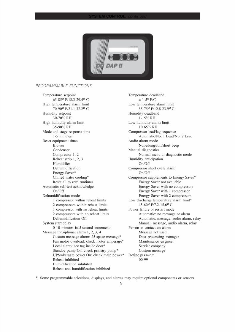
The microprocessor based Data Al arm Processor-I I TM offers the definite answer for precision
environmental control. The DAP-I I TM control system not only controls and monitors temperature,
humidity, airflow, and cleanliness, it provides component run times, alarm history, and an automatic self-
test of the microprocessor on system start-up. All messages are presented in a clear vernacular format and
sequentially displayed on a 2 row, 80 character, backlit liquid crystal display (LCD).
OPERATION - High reliability, flat, sealed switches with tactile feedback allow unit On/Off
operation, menu selection for programming, operational information, diagnostics, and historical
data. Multilevel password prevents unauthorized access. Alarm conditions are enunciated by an
audible alarm. The alarm silence switch will quiet the audible alarm but the display will continue to
indicate the alarm condition until the problem is corrected.
7/24/2019 DATA AIRE
http://slidepdf.com/reader/full/data-aire 9/76
9
PROGRAMMABLE FUNCTIONS
Temperature setpoint Temperature deadband
65-85o F/18.3-29.4o C ± 1-5o F/C
High temperature alarm limit Low temperature alarm limit
70-90o F/21.1-32.2o C 55-75o F/12.8-23.9o C
Humidity setpoint Humidity deadband
30-70% RH 1-15% RH
High humidity alarm limit Low humidity alarm limit
35-90% RH 10-65% RH
Mode and stage response time Compressor lead/lag sequence
1-5 minutes Automatic/No. 1 Lead/No. 2 Lead
Reset equipment times Audio alarm mode
Blower None/long/full/short beep
Condenser Manual diagnostics
Compressor 1, 2 Normal menu or diagnostic mode
Reheat strip 1, 2, 3 Humidity anticipation
Humidifier On/Off
Dehumidification Compressor short cycle alarm
Energy Saver* On/Off Chilled water cooling* Compressor supplements to Energy Saver*
Reset all to zero runtimes Energy Saver not available
Automatic self-test acknowledge Energy Saver with no compressors
On/Off Energy Saver with 1 compressor
Dehumidification mode Energy Saver with 2 compressors
1 compressor within reheat limits Low discharge temperature alarm limit*
2 compressors within reheat limits 45-60o F/7.2-15.6o C
1 compressor with no reheat limits Power failure or restart mode
2 compressors with no reheat limits Automatic: no message or alarm
Dehumidification Off Automatic: message, audio alarm, relay
System start delay Manual: message, audio alarm, relay
0-10 minutes in 5 second increments Person to contact on alarm
Message for optional alarm 1, 2, 3, 4 Message not usedCustom message alarm: 25 space message* Data processing manager
Fan motor overload: check motor amperage* Maintenance engineer
Local alarm: see tag inside door* Service company
Standby pump On: check primary pump* Custom message
UPS/alternate power On: check main power* Define password
Reheat inhibited 00-99
Humidification inhibited
Reheat and humidification inhibited
* Some programmable selections, displays, and alarms may require optional components or sensors.
SYSTEM CONTROL, cont inued
7/24/2019 DATA AIRE
http://slidepdf.com/reader/full/data-aire 10/76
10
PROGRAMM ABLE FUNCTI ONS, continued
Firestat temperature alarm limit
Unit shutdown and alarm at 100-150o F
Temperature scale
Fahrenheit/CentigradeUnit and network identification number
0 to 260
Remote alarm 1, 2, 3 selection*
Compressor short cycle
Custom message 1, 2, 3, and 4*
Dirty filter
Discharge air sensor problem*
Fan motor overload*
Firestat
High humidity
High pressure compressor 1
High pressure compressor 2
High temperature
Humidifier problem
Humidity sensor problem
Local alarm 1 ,2, 3, and 4*
Low humidity
Low pressure compressor 1
Low pressure compressor 2
Low temperature
Low voltage
Maintenance required
Manual override
No airflow
No water flow*Power problem or restart
Smoke detector*
Standby pump on*
Temperature sensor problem
Water detection probe
UPS/alternate power On
Reheat inhibited
Humidification inhibited
Reheat and humidification inhibited
Delay for optional alarm 1, 2, 3, and 4
0-900 seconds/Off
Humidifier autoflush timer*
Autoflush timer not used
6 hours
12-96 hours in 12 hour incrementsScheduled normal maintenance
1-1000 hours/off
Control logic
Setpoint deviation/PID/smart logic
Compressors
Primary/primary
Primary/secondary
Primary/secondary/primary/secondary*
Calibrate temperature sensor
+ 9.9o F/C
Calibrate humidity sensor
+ 30% RH
Calibrate discharge sensor*
9.9o F/C
Reheat stages
None
1, 2, or 3
Hot Water*
Humidifier
None
Computer, non-modulating
Computer, modulating
Comfort, non-modulating
Comfort, modulating
Water valve mode None
Chilled water cooling
Energy saver cooling
Auxiliary chilled water cooling
Water valve range
0 - 10 DC
4 - 7 DC
6 - 9 DC
7 - 10 DC
Reverse acting water valve
Yes/No
* Some programmable selections, displays, and alarms may require optional components or sensors.
SYSTEM CONTROL, cont inued
7/24/2019 DATA AIRE
http://slidepdf.com/reader/full/data-aire 11/76
11
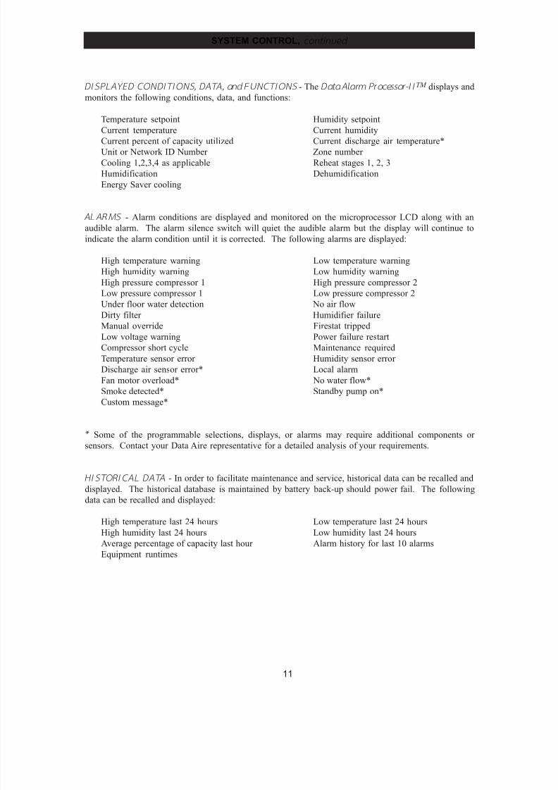
DI SPLAYED CONDIT IONS, DATA, and FUNCTI ONS - The Data Alarm Processor- I I TM displays and
monitors the following conditions, data, and functions:
Temperature setpoint Humidity setpoint
Current temperature Current humidity
Current percent of capacity utilized Current discharge air temperature*Unit or Network ID Number Zone number
Cooling 1,2,3,4 as applicable Reheat stages 1, 2, 3
Humidification Dehumidification
Energy Saver cooling
ALARMS - Alarm conditions are displayed and monitored on the microprocessor LCD along with an
audible alarm. The alarm silence switch will quiet the audible alarm but the display will continue to
indicate the alarm condition until it is corrected. The following alarms are displayed:
High temperature warning Low temperature warning
High humidity warning Low humidity warning
High pressure compressor 1 High pressure compressor 2
Low pressure compressor 1 Low pressure compressor 2
Under floor water detection No air flow
Dirty filter Humidifier failure
Manual override Firestat tripped
Low voltage warning Power failure restart
Compressor short cycle Maintenance required
Temperature sensor error Humidity sensor error
Discharge air sensor error* Local alarm
Fan motor overload* No water flow*
Smoke detected* Standby pump on*
Custom message*
* Some of the programmable selections, displays, or alarms may require additional components or
sensors. Contact your Data Aire representative for a detailed analysis of your requirements.
HI STORICAL DATA - In order to facilitate maintenance and service, historical data can be recalled and
displayed. The historical database is maintained by battery back-up should power fail. The following
data can be recalled and displayed:
High temperature last 24 hours Low temperature last 24 hours
High humidity last 24 hours Low humidity last 24 hours
Average percentage of capacity last hour Alarm history for last 10 alarms
Equipment runtimes
SYSTEM CONTROL, cont inued
7/24/2019 DATA AIRE
http://slidepdf.com/reader/full/data-aire 12/76
12
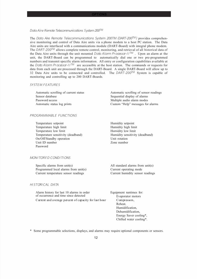
Data Ai re Remote Telecommuni cations System 200 TM
The Data A ir e Remote Telecommuni cations System 200TM (DART -200 TM ) provides comprehen-
sive monitoring and control of Data Aire units via a phone modem to a host PC station. The Data
Aire units are interfaced with a communications module (DART-Board) with integral phone modem.
The DART-200 TM allows complete remote control, monitoring, and retrieval of all historical data of the Data Aire units through the unit mounted Data Al arm Pr ocessor-I I TM . Upon an alarm at the
unit, the DART-Board can be programmed to automatical ly dial one or two pre-programmed
numbers and transmit specific alarm information. All entry or configuration capabilities available at
the Data Al arm Pr ocessor-I I TM are accessible at the host station. The commands or requests for
data from each unit are processed through the DART-Board. A single DART-Board will allow up to
32 Data Aire units to be connected and controlled. The DART-200 TM System is capable of
monitoring and controlling up to 200 DART-Boards.
SYSTEM FEATURES
Automatic scrolling of current status Automatic scrolling of sensor readings
Sensor database Sequential display of alarmsPassword access Multiple audio alarm modes
Automatic status log prints Custom “Help” messages for alarms
PROGRAMMABLE FUNCTIONS
Temperature setpoint Humidity setpoint
Temperature high limit Humidity high limit
Temperature low limit Humidity low limit
Temperature sensitivity (deadband) Humidity sensitivity (deadband)
On/Off/Standby operation Unit rotation
Unit ID number Zone number
Password
MONITORED CONDI TIONS
Specific alarms from unit(s) All standard alarms from unit(s)
Programmed local alarms from unit(s) Current operating mode
Current temperature sensor readings Current humidity sensor readings
HI STORICAL DATA
Alarm history for last 10 alarms in order Equipment runtimes for:
of occurrence and time since detected Evaporator motorsCurrent and average percent of capacity for last hour Compressors,
Reheat,
Humidification,
Dehumidification,
Energy Saver cooling*,
Chilled water cooling*.
* Some programmable selections, displays, and alarms may require optional components or sensors.
OPTIONS
7/24/2019 DATA AIRE
http://slidepdf.com/reader/full/data-aire 13/76
13
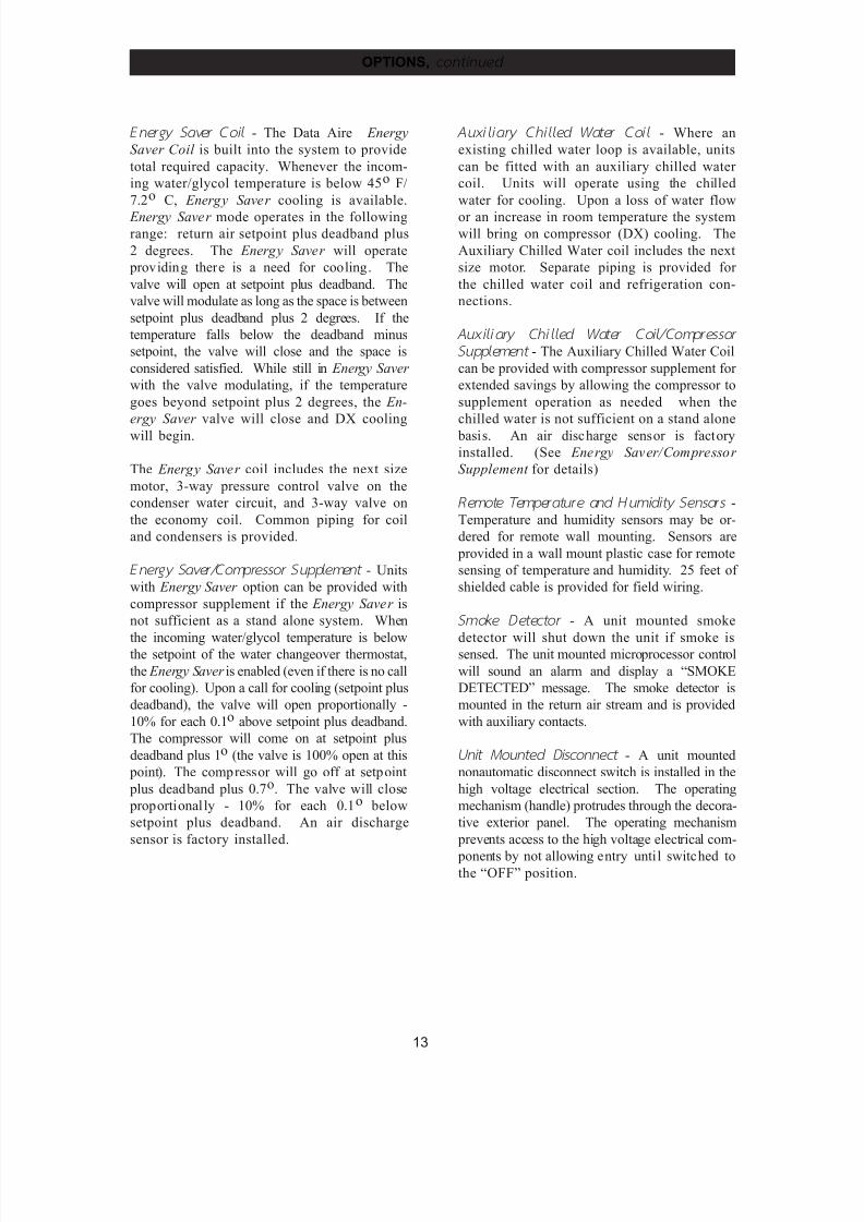
Energy Saver Coil - The Data Aire Energy
Saver Coil is built into the system to provide
total required capacity. Whenever the incom-
ing water/glycol temperature is below 45o F/
7.2o C, Energy Saver cooling is available.
Energy Saver mode operates in the followingrange: return air setpoint plus deadband plus
2 degrees. The Energy Saver will operate
providing there is a need for cooling. The
valve will open at setpoint plus deadband. The
valve will modulate as long as the space is between
setpoint plus deadband plus 2 degrees. If the
temperature falls below the deadband minus
setpoint, the valve will close and the space is
considered satisfied. While still in Energy Saver
with the valve modulating, if the temperature
goes beyond setpoint plus 2 degrees, the En-
ergy Saver valve will close and DX cooling
will begin.
The Energy Saver coil includes the next size
motor, 3-way pressure control valve on the
condenser water circuit, and 3-way valve on
the economy coil. Common piping for coil
and condensers is provided.
Energy Saver /Compressor Supplement - Units
with Energy Saver option can be provided with
compressor supplement if the Energy Saver is
not sufficient as a stand alone system. When
the incoming water/glycol temperature is belowthe setpoint of the water changeover thermostat,
the Energy Saver is enabled (even if there is no call
for cooling). Upon a call for cooling (setpoint plus
deadband), the valve will open proportionally -
10% for each 0.1o above setpoint plus deadband.
The compressor will come on at setpoint plus
deadband plus 1o (the valve is 100% open at this
point). The compressor will go off at setpoint
plus deadband plus 0.7o. The valve will close
proportional ly - 10% for each 0.1o below
setpoint plus deadband. An air discharge
sensor is factory installed.
Auxil iary Chil led Water Coil - Where an
existing chilled water loop is available, units
can be fitted with an auxiliary chilled water
coil. Units will operate using the chilled
water for cooling. Upon a loss of water flow
or an increase in room temperature the systemwill bring on compressor (DX) cooling. The
Auxiliary Chilled Water coil includes the next
size motor. Separate piping is provided for
the chilled water coil and refrigeration con-
nections.
Auxiliary Chilled Water Coil/Compressor
Supplement - The Auxiliary Chilled Water Coil
can be provided with compressor supplement for
extended savings by allowing the compressor to
supplement operation as needed when the
chilled water is not sufficient on a stand alone
basis. An air discharge sensor is factory
installed. (See Energy Saver/Compressor
Supplement for details)
Remote Temperatu re and Humi dity Sensors -
Temperature and humidity sensors may be or-
dered for remote wall mounting. Sensors are
provided in a wall mount plastic case for remote
sensing of temperature and humidity. 25 feet of
shielded cable is provided for field wiring.
Smoke Detector - A unit mounted smoke
detector will shut down the unit if smoke issensed. The unit mounted microprocessor control
will sound an alarm and display a “SMOKE
DETECTED” message. The smoke detector is
mounted in the return air stream and is provided
with auxiliary contacts.
Uni t M ounted Disconnect - A unit mounted
nonautomatic disconnect switch is installed in the
high voltage electrical section. The operating
mechanism (handle) protrudes through the decora-
tive exterior panel. The operating mechanism
prevents access to the high voltage electrical com-
ponents by not allowing entry until switched tothe “OFF” position.
OPTIONS, cont inued
7/24/2019 DATA AIRE
http://slidepdf.com/reader/full/data-aire 14/76
14
OPTIONS, cont inued
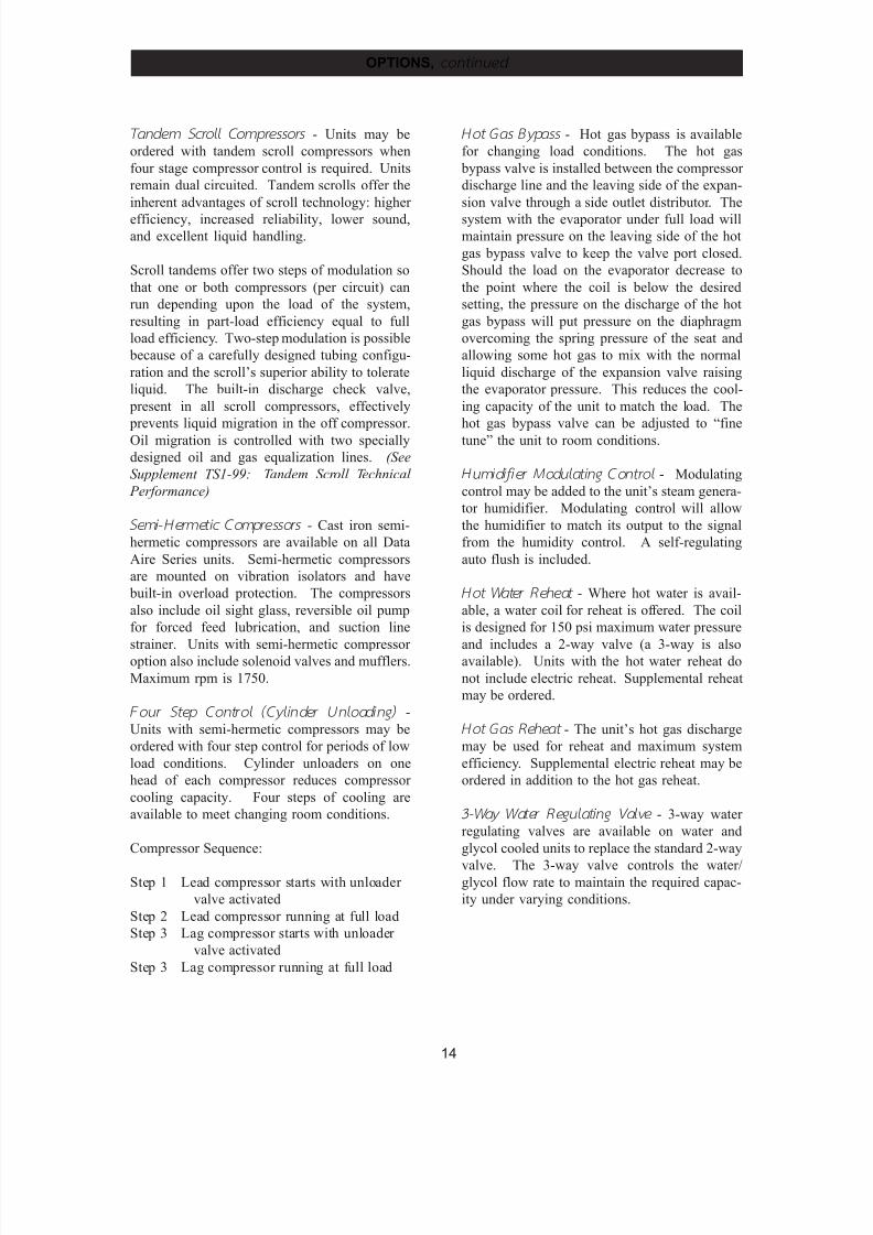
Tandem Scroll Compressors - Units may be
ordered with tandem scroll compressors when
four stage compressor control is required. Units
remain dual circuited. Tandem scrolls offer the
inherent advantages of scroll technology: higher
efficiency, increased reliability, lower sound,and excellent liquid handling.
Scroll tandems offer two steps of modulation so
that one or both compressors (per circuit) can
run depending upon the load of the system,
resulting in part-load efficiency equal to full
load efficiency. Two-step modulation is possible
because of a carefully designed tubing configu-
ration and the scroll’s superior ability to tolerate
liquid. The built-in discharge check valve,
present in all scroll compressors, effectively
prevents liquid migration in the off compressor.
Oil migration is controlled with two specially
designed oil and gas equalization lines. (See
Supplement TS1-99: Tandem Scroll Technical
Performance)
Semi -H ermetic Compressors - Cast iron semi-
hermetic compressors are available on all Data
Aire Series units. Semi-hermetic compressors
are mounted on vibration isolators and have
built-in overload protection. The compressors
also include oil sight glass, reversible oil pump
for forced feed lubrication, and suction line
strainer. Units with semi-hermetic compressor option also include solenoid valves and mufflers.
Maximum rpm is 1750.
Four Step Control (Cylinder Unloading) -
Units with semi-hermetic compressors may be
ordered with four step control for periods of low
load conditions. Cylinder unloaders on one
head of each compressor reduces compressor
cooling capacity. Four steps of cooling are
available to meet changing room conditions.
Compressor Sequence:
Step 1 Lead compressor starts with unloader
valve activated
Step 2 Lead compressor running at full load
Step 3 Lag compressor starts with unloader
valve activated
Step 3 Lag compressor running at full load
Hot Gas Bypass - Hot gas bypass is available
for changing load conditions. The hot gas
bypass valve is installed between the compressor
discharge line and the leaving side of the expan-
sion valve through a side outlet distributor. The
system with the evaporator under full load willmaintain pressure on the leaving side of the hot
gas bypass valve to keep the valve port closed.
Should the load on the evaporator decrease to
the point where the coil is below the desired
setting, the pressure on the discharge of the hot
gas bypass will put pressure on the diaphragm
overcoming the spring pressure of the seat and
allowing some hot gas to mix with the normal
liquid discharge of the expansion valve raising
the evaporator pressure. This reduces the cool-
ing capacity of the unit to match the load. The
hot gas bypass valve can be adjusted to “fine
tune” the unit to room conditions.
Humidifier M odulating Control - Modulating
control may be added to the unit’s steam genera-
tor humidifier. Modulating control will allow
the humidifier to match its output to the signal
from the humidity control. A self-regulating
auto flush is included.
Hot Water Reheat - Where hot water is avail-
able, a water coil for reheat is offered. The coil
is designed for 150 psi maximum water pressure
and includes a 2-way valve (a 3-way is alsoavailable). Units with the hot water reheat do
not include electric reheat. Supplemental reheat
may be ordered.
Hot Gas Reheat - The unit’s hot gas discharge
may be used for reheat and maximum system
efficiency. Supplemental electric reheat may be
ordered in addition to the hot gas reheat.
3-Way Water Regulating Valve - 3-way water
regulating valves are available on water and
glycol cooled units to replace the standard 2-way
valve. The 3-way valve controls the water/glycol flow rate to maintain the required capac-
ity under varying conditions.

7/24/2019 DATA AIRE
http://slidepdf.com/reader/full/data-aire 15/76
15
OPTIONS, cont inued
Upfl ow Air Discharge Plenum - Upflow air
discharge plenums are fully insulated with front
discharge grille. Side grilles for both or one side
are available. Plenums are 18” high and painted
to match the unit’s color.
Floorstands - Floorstands are adjustable (± 2
inches) and may be ordered with factory in-
stalled turning vane or with seismic construc-
tion.
H igh Effi ciency F ilters - Standard filters are
rated at 30% (per ASHRAE Std. 52-76). Higher
efficiency filters are available (consult factory
regarding efficiency percentage and unit static
pressures).
Condensate Pumps - Condensate pumps may be
ordered factory installed or shipped loose for
field installation. Condensate pumps are com-
plete with sump, motor, and automatic control.
Pumps shipped loose are available in 115, 230,
or 460 volts.
Pump Ratings:
230 volt:
with check valve - 40 GPH at 20 feet
without check valve - 130 GPH at 40 feet
460 volt:
with check valve - 50 GPH at 20 feet
without check valve - 270 GPH at 40 feet
Pump Package - Centrifugal pump packages are
available to circulate water or water/glycol solu-
tions. Pumps are available in various horse-
power and voltages. Both 3400 and 1750 rpm
pumps are available as an option.
Pump Enclosure - Pump enclosures are avail-
able for either single or dual pump applications.Pump enclosures are vented and weather resis-
tant. When ordered with pumps, the pumps are
factory mounted in the enclosure ready for field
piping and wiring.
I ntegral Pump Enclosures - Pumps may be
factory mounted as an integral part of the dry
cooler. A 30” extension is added to the dry
cooler. Pumps are pre-piped and wired and
includes shut-off valves. A flow switch is
included with dual pumps.
Pump Auto-Changeover - Dual pump packages
may be provided with a pump auto-changeover
control and NEMA 4 flow switch (field in-
stalled). The pump auto-changeover control is
factory wired and mounted in the dry cooler
control box. The pump auto-changeover control
provides automatic pump changeover in the
event of a pump failure. Upon pump
changeover, an audible alarm will sound at the
indoor unit and a message (“STANDBY PUMP
ON”) will be displayed on the indoor unit
microprocessor display.
Ex tended Compressor Warr anty - An extended
compressor warranty for a period of four (4)
years is available in addition to the standard
factory one (1) year warranty. The warranty is
for the replacement of compressors and does not
include labor.
7/24/2019 DATA AIRE
http://slidepdf.com/reader/full/data-aire 16/76
16
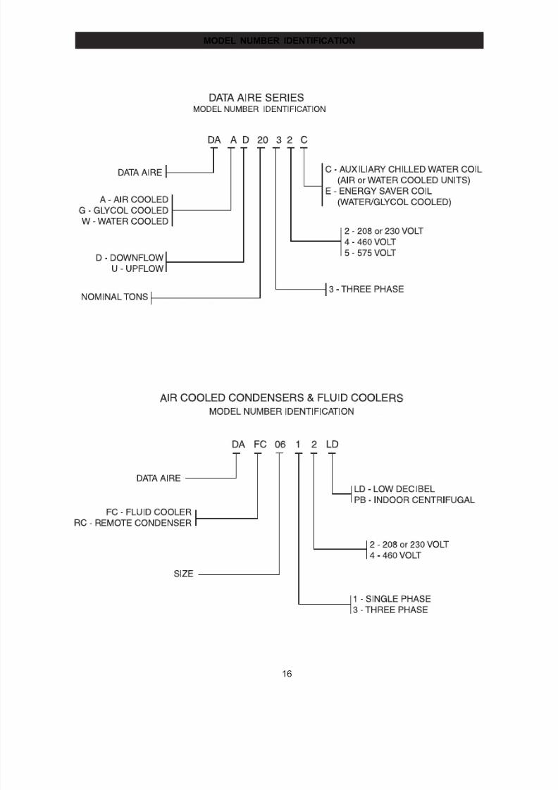
MODEL NUMBER IDENTIFICATION
7/24/2019 DATA AIRE
http://slidepdf.com/reader/full/data-aire 17/76
17
PERFORMANCE
and
ELECTRICAL DATA
7/24/2019 DATA AIRE
http://slidepdf.com/reader/full/data-aire 18/76
18
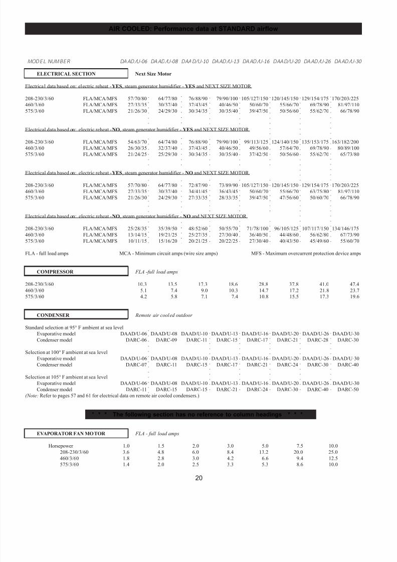
M ODEL NUM BER DAAD/U-06 DAAD/U-08 DAAD/U-10 DAAD/U-13 DAAD/U-16 DAAD/U-20 DAAD/U-26 DAAD/U-30
CAPACITY in Btu/hr
80o DB/67o WB Total 74,800 105,900 133,500 159,000 212,600 276,100 345,200 416,600
50% RH Sensible 59,600 84,100 107,700 122,600 159,400 197,400 248,500 310,200
75o DB/62.5o WB Total 68,500 97,500 123,000 146,600 194,500 261,900 311,100 379,900
50% RH Sensible 56,300 82,500 105,600 120,500 156,200 206,500 245,300 302,500
75o DB/61o WB Total 66,600 94,900 119,600 142,500 188,600 254,600 308,600 368,000
45% RH Sensible 62,200 88,100 112,800 128,300 165,900 219,400 259,100 321,900
72o DB/60o WB Total 65,600 92,800 117,200 140,100 185,800 247,900 302,500 362,500
50% RH Sensible 57,100 80,600 103,300 118,100 153,100 201,600 239,600 297,200
72o DB/58.6o WB Total 64,500 90,500 114,200 136,800 181,200 244,300 296,200 351,900
45% RH Sensible 61,100 85,800 109,900 125,500 162,400 214,800 253,900 314,500
BLOWER SECTION
Airflow - CFM 2,700 3,600 4,500 4,800 6,400 8,000 9,000 12,000Standard Motor - horsepower 1 2 3 3 3 5 7.5 3
External static pressure (E.S.P.) - inches of W.G. 0.5 0.5 0.5 0.5 0.5 0.5 0.5 0.5
Number of motors/fans 1/1 1/1 1/1 1/1 1/2 1/2 1/2 3/3
Maximum E.S.P. Downflow 0.8 1.0 1.2 0.7 1.0 1.2 1.5 1.5
(Standard motor) Upflow 0.7 0.9 1.0 0.6 0.9 1.1 1.5 1.5
Maximum E.S.P. Downflow 0.9 1.5 1.5 1.5 1.4 1.5 1.5 1.5
(Next Size motor) Upflow 0.9 1.5 1.0 1.5 1.3 1.5 1.5 1.5
Next size motor horsepower 1.5 3 5 5 5 7.5 10 5
COMPRESSORS
Type:Hermetic scroll Standard Standard Standard Standard Standard Standard Standard Standard
Semi-Hermetic Optional Optional Optional Optional Optional Optional Optional Optional
Number 2 2 2 2 2 2 2 2
Refrigerant type R-22 R-22 R-22 R-22 R-22 R-22 R-22 R-22
EVAPORATOR COIL
Face area - sq. ft. 12.2 12.2 12.2 14.5 24.4 24.4 24.4 32.5
Rows of coils 2 3 4 5 3 4 5 4
Face velocity - FPM 221 295 369 331 262 328 369 369
REHEAT SECTION
Electric Standard Standard Standard Standard Standard Standard Standard StandardkW 15 15 15 15 22.5 22.5 22.5 30
Capacity - Btu/hr 51,225 51,225 51,225 51,225 76,835 76,835 76,835 102,450
Hot gas Optional Optional Optional Optional Optional Optional Optional Optional
Capacity - Btu/hr 26,000 38,000 42,200 48,000 64,000 81,000 101,000 126,000
Steam Optional Optional Optional Optional Optional Optional Optional N/A
Capacity - Btu/hr Downflow 105,500 115,000 121,000 126,000 90,000 210,000 230,000 N/A
Upflow 60,000 65,000 69,000 72,000 108,000 120,000 130,000 N/A
Hot water Optional Optional Optional Optional Optional Optional Optional N/A
Capacity - Btu/hr Downflow 70,000 81,000 86,000 90,000 130,000 145,000 160,000 N/A
Upflow 34,300 44,800 47,500 49,400 74,200 82,000 90,700 N/A
AIR COOLED: Performance data at STANDARD airflow
7/24/2019 DATA AIRE
http://slidepdf.com/reader/full/data-aire 19/76
19
AIR COOLED: Performance data at STANDARD airflow
○
○
○
○
○
○
○
○
○
○
○
○
○
○
○
○
○
○
○
○
○
○
○
○
○
○
○
○
○
○
○
○
○
○
○
○
○
○
○
○
○
○
○
○
○
○
○
○
○
○
○
○
○
○
○
○
○
○
○
○
○
○
○
○
○
○
○
○
○
○
○
○
○
○
○
○
○
○
○
○
○
○
○
○
○
○
○
○
○
○
○
○
○
○
○
○
○
○
○
○
○
○
○
○
○
○
○
○
○
○
○
○
○
○
○
○
○
○
○
○
○
○
○
○
○
○
○
○
○
○
○
○
○
○
○
○
○
○
○
○
○
○
○
○
○
○
○
○
○
○
○
○
○
○
○
○
○
○
○
○
○
○
○
○
○
○
○
○
○
○
○
○
○
○
○
○
○
○
○
○
○
○
○
○
○
○
○
○
○
○
○
○
○
○
○
○
○
○
○
○
○
○
○
○
○
○
○
○
○
○
○
○
○
○
○
○
○
○
○
○
○
○
○
○
○
○
○
○
○
○
○
○
○
○
○
○
○
○
○
○
○
○
○
○
○
○
○
○
○
○
○
○
○
○
○
○
○
○
○
○
○
○
○
○
○
○
○
○
○
○
○
○
○
○
○
○
○
○
○
○
○
○
○
○
○
○
○
○
○
○
○
○
○
○
○
○
○
○
○
○
○
○
○
○
○
○
○
○
○
○
○
○
○
○
○
○
○
○
○
○
○
○
○
○
○
○
○
○
○
○
○
○
○
○
○
○
○
○
○
○
○
○
○
○
○
○
○
○
○
○
○
○
○
○
○
○
○
○
○
○
○
○
○
○
○
○
○
○
○
○
○
○
○
○
○
○
○
○
○
○
○
○
○
○
○
○
○
○
○
○
○
○
○
○
○
○
○
○
○
○
○
○
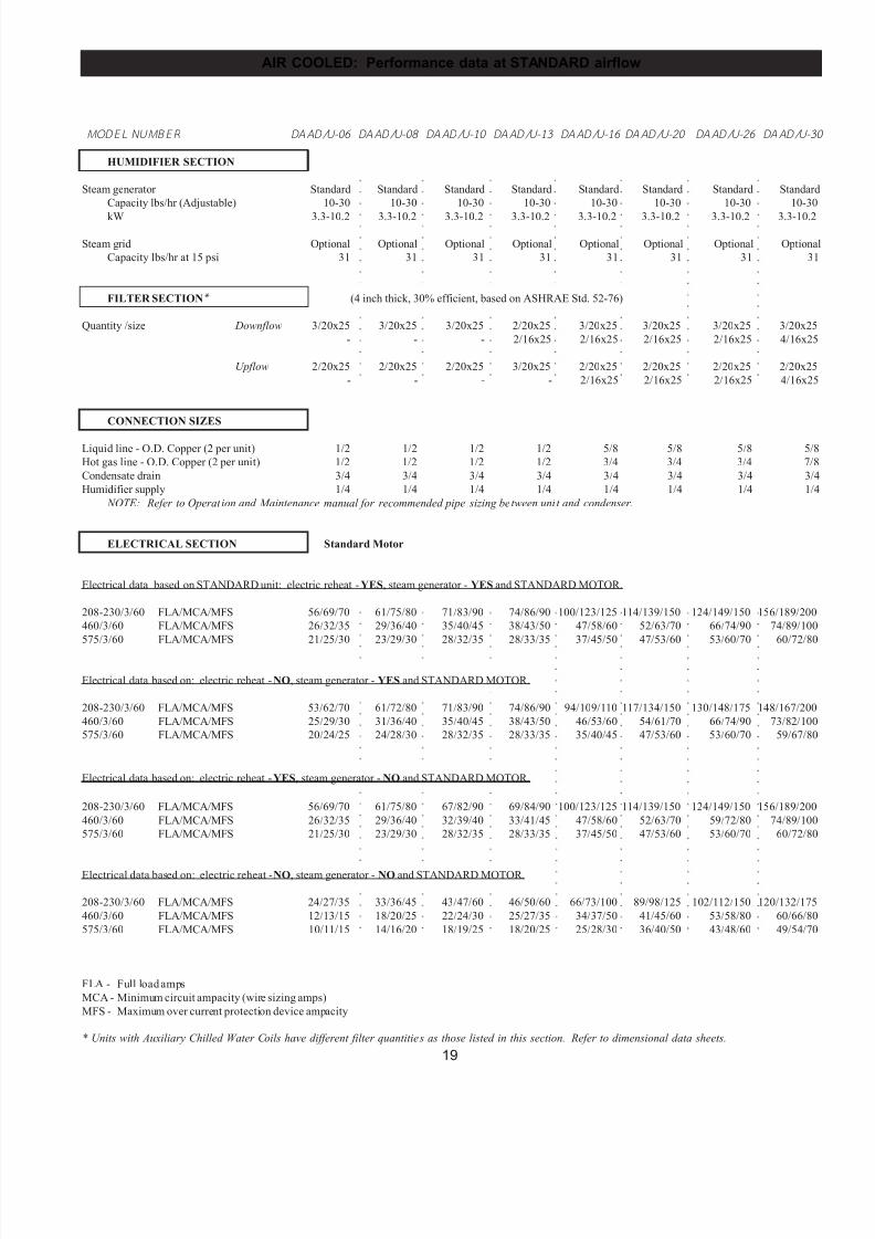
M ODEL NUM BER DAAD/U-06 DAAD/U-08 DAAD/U-10 DAAD/U-13 DAAD/U-16 DAAD/U-20 DAAD/U-26 DAAD/U-3
HUMIDIFIER SECTION
Steam generator Standard Standard Standard Standard Standard Standard Standard Standard
Capacity lbs/hr (Adjustable) 10-30 10-30 10-30 10-30 10-30 10-30 10-30 10-30
kW 3.3-10.2 3.3-10.2 3.3-10.2 3.3-10.2 3.3-10.2 3.3-10.2 3.3-10.2 3.3-10.2
Steam grid Optional Optional Optional Optional Optional Optional Optional Optional
Capacity lbs/hr at 15 psi 31 31 31 31 31 31 31 31
FILTER SECTION* (4 inch thick, 30% efficient, based on ASHRAE Std. 52-76)
Quantity /size Downflow 3/20x25 3/20x25 3/20x25 2/20x25 3/20x25 3/20x25 3/20x25 3/20x25
- - - 2/16x25 2/16x25 2/16x25 2/16x25 4/16x25
Upflow 2/20x25 2/20x25 2/20x25 3/20x25 2/20x25 2/20x25 2/20x25 2/20x25
- - - - 2/16x25 2/16x25 2/16x25 4/16x25
CONNECTION SIZES
Liquid line - O.D. Copper (2 per unit) 1/2 1/2 1/2 1/2 5/8 5/8 5/8 5/8
Hot gas line - O.D. Copper (2 per unit) 1/2 1/2 1/2 1/2 3/4 3/4 3/4 7/8
Condensate drain 3/4 3/4 3/4 3/4 3/4 3/4 3/4 3/4
Humidifier supply 1/4 1/4 1/4 1/4 1/4 1/4 1/4 1/4
NOTE: Refer to Operation and Maintenance manual for recommended pipe sizing between unit and condenser.
ELECTRICAL SECTION Standard Motor
Electrical data based on STANDARD unit: electric reheat - YES, steam generator - YES and STANDARD MOTOR.
208-230/3/60 FLA/MCA/MFS 56/69/70 61/75/80 71/83/90 74/86/90 100/123/125 114/139/150 124/149/150 156/189/200
460/3/60 FLA/MCA/MFS 26/32/35 29/36/40 35/40/45 38/43/50 47/58/60 52/63/70 66/74/90 74/89/100
575/3/60 FLA/MCA/MFS 21/25/30 23/29/30 28/32/35 28/33/35 37/45/50 47/53/60 53/60/70 60/72/80
Electrical data based on: electric reheat - NO, steam generator - YES and STANDARD MOTOR.
208-230/3/60 FLA/MCA/MFS 53/62/70 61/72/80 71/83/90 74/86/90 94/109/110 117/134/150 130/148/175 148/167/200
460/3/60 FLA/MCA/MFS 25/29/30 31/36/40 35/40/45 38/43/50 46/53/60 54/61/70 66/74/90 73/82/100
575/3/60 FLA/MCA/MFS 20/24/25 24/28/30 28/32/35 28/33/35 35/40/45 47/53/60 53/60/70 59/67/80
Electrical data based on: electric reheat - YES, steam generator - NO and STANDARD MOTOR.
208-230/3/60 FLA/MCA/MFS 56/69/70 61/75/80 67/82/90 69/84/90 100/123/125 114/139/150 124/149/150 156/189/200
460/3/60 FLA/MCA/MFS 26/32/35 29/36/40 32/39/40 33/41/45 47/58/60 52/63/70 59/72/80 74/89/100
575/3/60 FLA/MCA/MFS 21/25/30 23/29/30 28/32/35 28/33/35 37/45/50 47/53/60 53/60/70 60/72/80
Electrical data based on: electric reheat - NO, steam generator - NO and STANDARD MOTOR.
208-230/3/60 FLA/MCA/MFS 24/27/35 33/36/45 43/47/60 46/50/60 66/73/100 89/98/125 102/112/150 120/132/175
460/3/60 FLA/MCA/MFS 12/13/15 18/20/25 22/24/30 25/27/35 34/37/50 41/45/60 53/58/80 60/66/80
575/3/60 FLA/MCA/MFS 10/11/15 14/16/20 18/19/25 18/20/25 25/28/30 36/40/50 43/48/60 49/54/70
FLA - Full load amps
MCA - Minimum circuit ampacity (wire sizing amps)
MFS - Maximum over current protection device ampacity
* Units with Auxiliary Chilled Water Coils have different filter quantities as those listed in this section. Refer to dimensional data sheets.
7/24/2019 DATA AIRE
http://slidepdf.com/reader/full/data-aire 20/76
20
AIR COOLED: Performance data at STANDARD airflow
○
○
○
○
○
○
○
○
○
○
○
○
○
○
○
○
○
○
○
○
○
○
○
○
○
○
○
○
○
○
○
○
○
○
○
○
○
○
○
○
○
○
○
○
○
○
○
○
○
○
○
○
○
○
○
○
○
○
○
○
○
○
○
○
○
○
○
○
○
○
○
○
○
○
○
○
○
○
○
○
○
○
○
○
○
○
○
○
○
○
○
○
○
○
○
○
○
○
○
○
○
○
○
○
○
○
○
○
○
○
○
○
○
○
○
○
○
○
○
○
○
○
○
○
○
○
○
○
○
○
○
○
○
○
○
○
○
○
○
○
○
○
○
○
○
○
○
○
○
○
○
○
○
○
○
○
○
○
○
○
○
○
○
○
○
○
○
○
○
○
○
○
○
○
○
○
○
○
○
○
○
○
○
○
○
○
○
○
○
○
○
○
○
○
○
○
○
○
○
○
○
○
○
○
○
○
○
○
○
○
○
○
○
○
○
○
○
○
○
○
○
○
○
○
○
○
○
○
○
○
○
○
○
○
○
○
○
○
○
○
○
○
○
○
○
○
○
○
○
○
○
○
○
○
○
○
○
○
○
○
○
○
○
○
○
○
○
○
○
○
○
○
○
○
○
○
○
○
○
○
○
○
○
○
○
○
○
○
○
○
○
○
○
○
○
○
○
○
○
○
○
○
○
○
○
○
○
○
○
○
○
○
○
○
○
○
○
○
○
○
○
○
○
○
○
○
○
○
○
○
○
○
○
○
○
○
○
○
○
○
○
○
○
○
○
○
○
○
○
○
○
○
○
○
○
○
○
○
○
○
○
○
○
○
○
○
○
○
○
○
○
○
○
○
○
○
○
M ODEL NUM BER DAAD/U-06 DAAD/U-08 DAAD/U-10 DAAD/U-13 DAAD/U-16 DAAD/U-20 DAAD/U-26 DAAD/U-30
ELECTRICAL SECTION Next Size Motor
Electrical data based on: electric reheat - YES, steam generator humidifier - YES and NEXT SIZE MOTOR.
208-230/3/60 FLA/MCA/MFS 57/70/80 64/77/80 76/88/90 79/90/100 105/127/150 120/145/150 129/154/175 170/203/225460/3/60 FLA/MCA/MFS 27/33/35 30/37/40 37/43/45 40/46/50 50/60/70 55/66/70 69/78/90 81/97/110
575/3/60 FLA/MCA/MFS 21/26/30 24/29/30 30/34/35 30/35/40 39/47/50 50/56/60 55/62/70 66/78/90
Electrical data based on: electric reheat - NO, steam generator humidifier - YES and NEXT SIZE MOTOR.
208-230/3/60 FLA/MCA/MFS 54/63/70 64/74/80 76/88/90 79/90/100 99/113/125 124/140/150 135/153/175 163/182/200
460/3/60 FLA/MCA/MFS 26/30/35 32/37/40 37/43/45 40/46/50 49/56/60 57/64/70 69/78/90 80/89/100
575/3/60 FLA/MCA/MFS 21/24/25 25/29/30 30/34/35 30/35/40 37/42/50 50/56/60 55/62/70 65/73/80
Electrical data based on: electric reheat - YES, steam generator humidifier - NO and NEXT SIZE MOTOR.
208-230/3/60 FLA/MCA/MFS 57/70/80 64/77/80 72/87/90 73/89/90 105/127/150 120/145/150 129/154/175 170/203/225
460/3/60 FLA/MCA/MFS 27/33/35 30/37/40 34/41/45 36/43/45 50/60/70 55/66/70 63/75/80 81/97/110
575/3/60 FLA/MCA/MFS 21/26/30 24/29/30 27/33/35 28/33/35 39/47/50 47/56/60 50/60/70 66/78/90
Electrical data based on: electric reheat - NO, steam generator humidifier - NO and NEXT SIZE MOTOR.
208-230/3/60 FLA/MCA/MFS 25/28/35 35/39/50 48/52/60 50/55/70 71/78/100 96/105/125 107/117/150 134/146/175
460/3/60 FLA/MCA/MFS 13/14/15 19/21/25 25/27/35 27/30/40 36/40/50 44/48/60 56/62/80 67/73/90
575/3/60 FLA/MCA/MFS 10/11/15 15/16/20 20/21/25 20/22/25 27/30/40 40/43/50 45/49/60 55/60/70
FLA - full load amps MCA - Minimum circuit amps (wire size amps) MFS - Maximum overcurrent protection device amps
COMPRESSOR FLA -full load amps
208-230/3/60 10.3 13.5 17.3 18.6 28.8 37.8 41.0 47.4
460/3/60 5.1 7.4 9.0 10.3 14.7 17.2 21.8 23.7
575/3/60 4.2 5.8 7.1 7.4 10.8 15.5 17.3 19.6
CONDENSER Remote air cooled outdoor
Standard selection at 95° F ambient at sea level
Evaporative model DAAD/U-06 DAAD/U-08 DAAD/U-10 DAAD/U-13 DAAD/U-16 DAAD/U-20 DAAD/U-26 DAAD/U-30
Condenser model DARC-06 DARC-09 DARC-11 DARC-15 DARC-17 DARC-21 DARC-28 DARC-30
Selection at 100° F ambient at sea level
Evaporative model DAAD/U-06 DAAD/U-08 DAAD/U-10 DAAD/U-13 DAAD/U-16 DAAD/U-20 DAAD/U-26 DAAD/U-30
Condenser model DARC-07 DARC-11 DARC-15 DARC-17 DARC-21 DARC-24 DARC-30 DARC-40
Selection at 105° F ambient at sea level
Evaporative model DAAD/U-06 DAAD/U-08 DAAD/U-10 DAAD/U-13 DAAD/U-16 DAAD/U-20 DAAD/U-26 DAAD/U-30
Condenser model DARC-11 DARC-15 DARC-15 DARC-21 DARC-24 DARC-30 DARC-40 DARC-50
(Note: Refer to pages 57 and 61 for electrical data on remote air cooled condensers.)
* * * The following section has no reference to column headings * * *
EVAPORATOR FAN MOTOR FLA - full load amps
Horsepower 1.0 1.5 2.0 3.0 5.0 7.5 10.0
208-230/3/60 3.6 4.8 6.0 8.4 13.2 20.0 25.0
460/3/60 1.8 2.8 3.0 4.2 6.6 9.4 12.5
575/3/60 1.4 2.0 2.5 3.3 5.3 8.6 10.0
7/24/2019 DATA AIRE
http://slidepdf.com/reader/full/data-aire 21/76
21
MODEL NUM BER DAAD/U-06 DAAD/U-08 DAAD/U-10 DAAD/U-13 DAAD/U-16 DAAD/U-20 DAAD/U-26 DAAD/U-3
CAPACITY in Btu/hr
80° F/67° WB Total 76,700 109,000 136,200 170,800 219,700 289,700 351,700 419,100
50% RH Sensible 65,200 94,200 120,800 137,500 180,100 212,400 263,100 334,700
75° DB/62.5° WB Total 70,000 99,800 126,100 158,100 201,400 266,900 323,800 387,600
50% RH Sensible 63,400 92,100 118,500 135,200 176,200 219,900 258,600 329,000
75° DB/61° WB Total 68,200 97,200 122,600 153,600 196,000 259,600 314,800 377,600
45% RH Sensible 68,200 96,700 122,000 144,300 188,500 234,400 274,900 351,500
72° DB/60° WB Total 67,000 95,100 120,600 150,600 191,900 254,200 308,600 370,300
50% RH Sensible 62,200 89,800 115,800 132,200 172,100 215,100 253,300 322,100
72° DB/58.6° WB Total 65,700 93,100 117,500 146,500 188,300 247,800 300,600 361,300
45% RH Sensible 65,500 92,600 116,900 140,600 184,100 228,500 268,400 342,900
BLOWER SECTION
Airflow - CFM 3,300 4,400 5,500 5,600 8,000 9,000 10,000 14,000Standard motor - horsepower 1.5 3 5 5 5 7.5 7.5 3
External static pressure (E.S.P.) - inches of W.G. 0.5 0.5 0.5 0.5 0.5 0.5 0.5 0.5
Number of motors/fans 1/1 1/1 1/1 1/1 1/2 1/2 1/2 3/3
Maximum E.S.P. Downflow 0.9 1.2 1.2 1.1 1.2 1.5 1.0 0.6
(Standard Motor) Upflow 0.7 0.9 1.0 0.6 0.9 1.1 1.6 0.5
Maximum E.S.P. Downflow 1.5 1.5 1.2 1.1 1.5 1.5 1.5 1.5
(Next Size Motor) Upflow 1.5 1.5 0.9 1.0 1.5 1.5 1.5 1.5
Next size motor - horsepower 2 5 7.5 7.5 7.5 10 10 5
COMPRESSORS
Type:
Hermetic scroll Standard Standard Standard Standard Standard Standard Standard Standard
Semi-hermetic Optional Optional Optional Optional Optional Optional Optional Optional
Number 2 2 2 2 2 2 2 2
Refrigerant type R-22 R-22 R-22 R-22 R-22 R-22 R-22 R-22
EVAPORATOR COIL
Face area - sq ft . 12.2 12.2 12.2 14.5 24.4 24.4 24.4 32.5
Rows of coils 2 3 4 5 3 4 5 4
Face velocity - fpm 271 361 451 386 328 369 410 431
REHEAT SECTION
Electric Standard Standard Standard Standard Standard Standard Standard Standard
kW 15 15 15 15 22.5 22.5 22.5 30
Capacity - Btu/hr 51,225 51,225 51,225 51,225 76,835 76,835 76,835 102,450
Hot gas Optional Optional Optional Optional Optional Optional Optional Optional
Capacity - Btu/hr 26,000 38,000 42,200 48,000 64,000 81,000 101,000 126,000
Steam Optional Optional Optional Optional Optional Optional Optional N/A
Capacity - Btu/hr Downflow 105,500 115,000 121,000 126,000 190,000 210,000 230,000 N/A
Upflow 60,000 65,000 69,000 72,000 108,000 120,000 130,000 N/A
Hot water Optional Optional Optional Optional Optional Optional Optional N/A
Capacity - Btu/hr Downflow 70,000 81,000 86,000 90,000 130,000 145,000 160,000 N/A
Upflow 34,300 44,800 47,500 49,400 74,200 82,000 90,700 N/A
AIR COOLED: Performance data at OPTIONAL airflow
7/24/2019 DATA AIRE
http://slidepdf.com/reader/full/data-aire 22/76
22
AIR COOLED: Performance data at OPTIONAL airflow
○
○
○
○
○
○
○
○
○
○
○
○
○
○
○
○
○
○
○
○
○
○
○
○
○
○
○
○
○
○
○
○
○
○
○
○
○
○
○
○
○
○
○
○
○
○
○
○
○
○
○
○
○
○
○
○
○
○
○
○
○
○
○
○
○
○
○
○
○
○
○
○
○
○
○
○
○
○
○
○
○
○
○
○
○
○
○
○
○
○
○
○
○
○
○
○
○
○
○
○
○
○
○
○
○
○
○
○
○
○
○
○
○
○
○
○
○
○
○
○
○
○
○
○
○
○
○
○
○
○
○
○
○
○
○
○
○
○
○
○
○
○
○
○
○
○
○
○
○
○
○
○
○
○
○
○
○
○
○
○
○
○
○
○
○
○
○
○
○
○
○
○
○
○
○
○
○
○
○
○
○
○
○
○
○
○
○
○
○
○
○
○
○
○
○
○
○
○
○
○
○
○
○
○
○
○
○
○
○
○
○
○
○
○
○
○
○
○
○
○
○
○
○
○
○
○
○
○
○
○
○
○
○
○
○
○
○
○
○
○
○
○
○
○
○
○
○
○
○
○
○
○
○
○
○
○
○
○
○
○
○
○
○
○
○
○
○
○
○
○
○
○
○
○
○
○
○
○
○
○
○
○
○
○
○
○
○
○
○
○
○
○
○
○
○
○
○
○
○
○
○
○
○
○
○
○
○
○
○
○
○
○
○
○
○
○
○
○
○
○
○
○
○
○
○
○
○
○
○
○
○
○
○
○
○
○
○
○
○
○
○
○
○
○
○
○
○
○
○
○
○
○
○
○
○
○
○
○
○
○
○
○
○
○
○
○
○
○
○
○
○
○
○
○
○
○
○
○
○
○
○
○
○
○
○
○
○
○
○
○
○
○
○
○
○
○
○
○
○
○
○
○
○
○
○
○
○
○
○
○
○
○
○
○
○
○
○
○
○
○
○
○
○
○
○
○
○
○
○
○
○
○
○
○
○
○
○
○
○
○
○
○
○
○
○
○
○
○
○
○
○
○
○
○
○
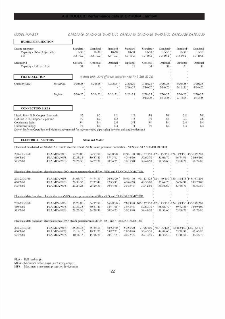
M ODEL NUM BER DAAD/U-06 DAAD/U-08 DAAD/U-10 DAAD/U-13 DAAD/U-16 DAAD/U-20 DAAD/U-26 DAAD/U-30
HUMIDIFIER SECTION
Steam generator Standard Standard Standard Standard Standard Standard Standard Standard
Capacity - lb/hr (Adjustable) 10-30 10-30 10-30 10-30 10-30 10-30 10-30 10-30
kW 3.3-10.2 3.3-10.2 3.3-10.2 3.3-10.2 3.3-10.2 3.3-10.2 3.3-10.2 3.3-10.2
Steam grid Optional Optional Optional Optional Optional Optional Optional Optional
Capacity - lb/hr at 15 psi 31 31 31 31 31 31 31 31
FILTER SECTION (4 inch th ick, 30% effi cient, based on ASHRAE Std. 52-76)
Quantity/Size Downflow 3/20x25 3/20x25 3/20x25 2/20x25 3/20x25 3/20x25 3/20x25 3/20x25
- - - 2/16x25 2/16x25 2/16x25 2/16x25 4/16x25
Upflow 2/20x25 2/20x25 2/20x25 3/20x25 2/20x25 2/20x25 2/20x25 2/20x25
- - - - 2/16x25 2/16x25 2/16x25 4/16x25
CONNECTION SIZES
Liquid line - O.D. Copper 2 per unit 1/2 1/2 1/2 1/2 5/8 5/8 5/8 5/8
Hot line - O.D. Copper 2 per unit 1/2 1/2 1/2 1/2 3/4 3/4 3/4 7/8
Condensate drain 3/4 3/4 3/4 3/4 3/4 3/4 3/4 3/4
Humidifier supply 1/4 1/4 1/4 1/4 1/4 1/4 1/4 1/4
(Note: Refer to Operation and Maintenance manual for recommended pipe sizing between unit and condenser.)
ELECTRICAL SECTION Standard Motor
Electrical data based on STANDARD unit: electric reheat - YES, steam generator humidifier - YES, and STANDARD MOTOR.
208-230/3/60 FLA/MCA/MFS 57/70/80 64/77/80 76/88/90 79/90/100 105/127/150 120/145/150 124/149/150 156/189/200
460/3/60 FLA/MCA/MFS 27/33/35 30/37/40 37/43/45 40/46/50 50/60/70 55/66/70 66/74/90 74/89/100
575/3/60 FLA/MCA/MFS 21/26/30 24/29/30 30/34/35 30/35/40 39/47/50 50/56/60 53/60/70 60/72/80
Electrical data based on: electrical reheat -NO, steam generator humidifier - YES, and STANDARD MOTOR.
208-230/3/60 FLA/MCA/MFS 54/63/70 64/74/80 76/88/90 79/90/100 99/113/125 124/140/150 130/148/175 148/167/200
460/3/60 FLA/MCA/MFS 26/30/35 32/37/40 37/43/45 40/46/50 49/56/60 57/64/70 66/74/90 73/82/100
575/3/60 FLA/MCA/MFS 21/24/25 25/29/30 30/34/35 30/35/45 37/42/50 50/56/60 53/60/70 59/67/80
Electrical data based on: electrical reheat -YES, steam generator humidifier - NO, and STANDARD MOTOR.
208-230/3/60 FLA/MCA/MFS 57/70/80 64/77/80 76/88/90 73/89/90 105/127/150 120/145/150 124/149/150 156/189/200
460/3/60 FLA/MCA/MFS 27/33/35 30/37/40 34/41/45 36/43/45 50/60/70 55/66/70 59/72/80 74/89/100
575/3/60 FLA/MCA/MFS 21/26/30 24/29/30 30/34/35 30/35/40 39/47/50 50/56/60 53/60/70 60/72/80
Electrical data based on: electrical reheat -NO, steam generator humidifier - NO, and STANDARD MOTOR.
208-230/3/60 FLA/MCA/MFS 25/28/35 35/39/50 48/52/60 50/55/70 71/78/100 96/105/125 102/112/150 120/132/175
460/3/60 FLA/MCA/MFS 13/14/15 19/21/25 25/27/35 27/30/40 36/40/50 44/48/60 53/58/80 60/66/80
575/3/60 FLA/MCA/MFS 10/11/15 15/16/20 20/21/25 20/22/25 27/30/40 40/43/50 43/48/60 49/54/70
FLA - Full load amps
MCA - Minimum circuit amps (wire sizing amps)
MFS - Maximum overcurrent protection device amps
7/24/2019 DATA AIRE
http://slidepdf.com/reader/full/data-aire 23/76
23
AIR COOLED: Performance data at OPTIONAL airflow
○
○
○
○
○
○
○
○
○
○
○
○
○
○
○
○
○
○
○
○
○
○
○
○
○
○
○
○
○
○
○
○
○
○
○
○
○
○
○
○
○
○
○
○
○
○
○
○
○
○
○
○
○
○
○
○
○
○
○
○
○
○
○
○
○
○
○
○
○
○
○
○
○
○
○
○
○
○
○
○
○
○
○
○
○
○
○
○
○
○
○
○
○
○
○
○
○
○
○
○
○
○
○
○
○
○
○
○
○
○
○
○
○
○
○
○
○
○
○
○
○
○
○
○
○
○
○
○
○
○
○
○
○
○
○
○
○
○
○
○
○
○
○
○
○
○
○
○
○
○
○
○
○
○
○
○
○
○
○
○
○
○
○
○
○
○
○
○
○
○
○
○
○
○
○
○
○
○
○
○
○
○
○
○
○
○
○
○
○
○
○
○
○
○
○
○
○
○
○
○
○
○
○
○
○
○
○
○
○
○
○
○
○
○
○
○
○
○
○
○
○
○
○
○
○
○
○
○
○
○
○
○
○
○
○
○
○
○
○
○
○
○
○
○
○
○
○
○
○
○
○
○
○
○
○
○
○
○
○
○
○
○
○
○
○
○
○
○
○
○
○
○
○
○
○
○
○
○
○
○
○
○
○
○
○
○
○
○
○
○
○
○
○
○
○
○
○
○
○
○
○
○
○
○
○
○
○
○
○
○
○
○
○
○
○
○
○
○
○
○
○
○
○
○
○
○
○
○
○
○
○
○
○
○
○
○
○
○
○
○
○
○
○
○
○
○
○
○
○
○
○
○
○
○
○
○
○
○
○
○
○
○
○
○
○
○
○
○
○
○
○
○
○
○
○
○
○
○
○
○
○
○
○
○
○
○
○
○
○
○
○
○
○
○
○
○
○
○
○
○
○
○
○
○
○
○
○
○
○
○
○
○
○
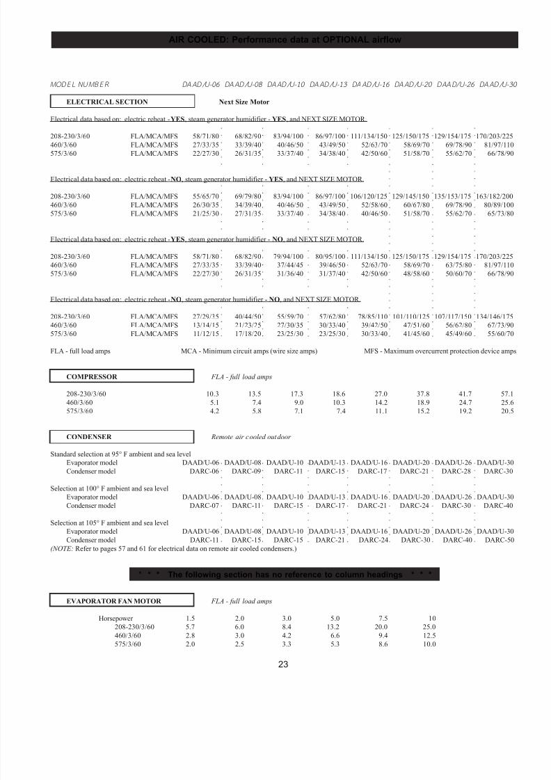
M ODEL NUM BER DAAD/U-06 DAAD/U-08 DAAD/U-10 DAAD/U-13 DAAD/U-16 DAAD/U-20 DAAD/U-26 DAAD/U-30
ELECTRICAL SECTION Next Size Motor
Electrical data based on: electric reheat - YES, steam generator humidifier - YES, and NEXT SIZE MOTOR.
208-230/3/60 FLA/MCA/MFS 58/71/80 68/82/90 83/94/100 86/97/100 111/134/150 125/150/175 129/154/175 170/203/225460/3/60 FLA/MCA/MFS 27/33/35 33/39/40 40/46/50 43/49/50 52/63/70 58/69/70 69/78/90 81/97/110
575/3/60 FLA/MCA/MFS 22/27/30 26/31/35 33/37/40 34/38/40 42/50/60 51/58/70 55/62/70 66/78/90
Electrical data based on: electric reheat - NO, steam generator humidifier - YES, and NEXT SIZE MOTOR.
208-230/3/60 FLA/MCA/MFS 55/65/70 69/79/80 83/94/100 86/97/100 106/120/125 129/145/150 135/153/175 163/182/200
460/3/60 FLA/MCA/MFS 26/30/35 34/39/40 40/46/50 43/49/50 52/58/60 60/67/80 69/78/90 80/89/100
575/3/60 FLA/MCA/MFS 21/25/30 27/31/35 33/37/40 34/38/40 40/46/50 51/58/70 55/62/70 65/73/80
Electrical data based on: electric reheat - YES, steam generator humidifier - NO, and NEXT SIZE MOTOR.
208-230/3/60 FLA/MCA/MFS 58/71/80 68/82/90 79/94/100 80/95/100 111/134/150 125/150/175 129/154/175 170/203/225
460/3/60 FLA/MCA/MFS 27/33/35 33/39/40 37/44/45 39/46/50 52/63/70 58/69/70 63/75/80 81/97/110
575/3/60 FLA/MCA/MFS 22/27/30 26/31/35 31/36/40 31/37/40 42/50/60 48/58/60 50/60/70 66/78/90
Electrical data based on: electric reheat - NO, steam generator humidifier - NO, and NEXT SIZE MOTOR.
208-230/3/60 FLA/MCA/MFS 27/29/35 40/44/50 55/59/70 57/62/80 78/85/110 101/110/125 107/117/150 134/146/175
460/3/60 FLA/MCA/MFS 13/14/15 21/23/25 27/30/35 30/33/40 39/42/50 47/51/60 56/62/80 67/73/90
575/3/60 FLA/MCA/MFS 11/12/15 17/18/20 23/25/30 23/25/30 30/33/40 41/45/60 45/49/60 55/60/70
FLA - full load amps MCA - Minimum circuit amps (wire size amps) MFS - Maximum overcurrent protection device amps
COMPRESSOR FLA - full load amps
208-230/3/60 10.3 13.5 17.3 18.6 27.0 37.8 41.7 57.1
460/3/60 5.1 7.4 9.0 10.3 14.2 18.9 24.7 25.6
575/3/60 4.2 5.8 7.1 7.4 11.1 15.2 19.2 20.5
CONDENSER Remote air cooled outdoor
Standard selection at 95° F ambient and sea level
Evaporator model DAAD/U-06 DAAD/U-08 DAAD/U-10 DAAD/U-13 DAAD/U-16 DAAD/U-20 DAAD/U-26 DAAD/U-30
Condenser model DARC-06 DARC-09 DARC-11 DARC-15 DARC-17 DARC-21 DARC-28 DARC-30
Selection at 100° F ambient and sea level
Evaporator model DAAD/U-06 DAAD/U-08 DAAD/U-10 DAAD/U-13 DAAD/U-16 DAAD/U-20 DAAD/U-26 DAAD/U-30
Condenser model DARC-07 DARC-11 DARC-15 DARC-17 DARC-21 DARC-24 DARC-30 DARC-40
Selection at 105° F ambient and sea level
Evaporator model DAAD/U-06 DAAD/U-08 DAAD/U-10 DAAD/U-13 DAAD/U-16 DAAD/U-20 DAAD/U-26 DAAD/U-30
Condenser model DARC-11 DARC-15 DARC-15 DARC-21 DARC-24 DARC-30 DARC-40 DARC-50
(NOTE: Refer to pages 57 and 61 for electrical data on remote air cooled condensers.)
* * * The following section has no reference to column headings * * *
EVAPORATOR FAN MOTOR FLA - full load amps
Horsepower 1.5 2.0 3.0 5.0 7.5 10
208-230/3/60 5.7 6.0 8.4 13.2 20.0 25.0
460/3/60 2.8 3.0 4.2 6.6 9.4 12.5
575/3/60 2.0 2.5 3.3 5.3 8.6 10.0
7/24/2019 DATA AIRE
http://slidepdf.com/reader/full/data-aire 24/76
24
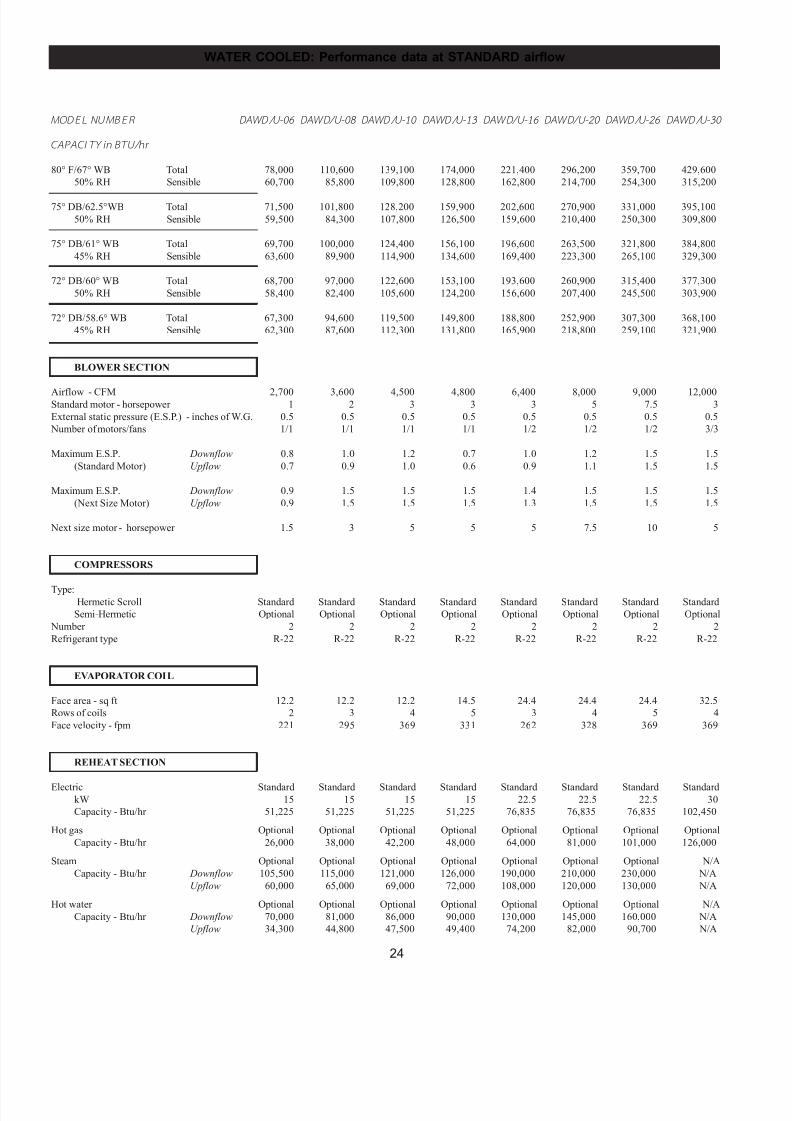
MODEL NUM BER DAWD/U-06 DAWD/U-08 DAWD/U-10 DAWD/U-13 DAWD/U-16 DAWD/U-20 DAWD/U-26 DAWD/U-30
CAPACITY in BTU/hr
80° F/67° WB Total 78,000 110,600 139,100 174,000 221,400 296,200 359,700 429,600
50% RH Sensible 60,700 85,800 109,800 128,800 162,800 214,700 254,300 315,200
75° DB/62.5°WB Total 71,500 101,800 128,200 159,900 202,600 270,900 331,000 395,100
50% RH Sensible 59,500 84,300 107,800 126,500 159,600 210,400 250,300 309,800
75° DB/61° WB Total 69,700 100,000 124,400 156,100 196,600 263,500 321,800 384,800
45% RH Sensible 63,600 89,900 114,900 134,600 169,400 223,300 265,100 329,300
72° DB/60° WB Total 68,700 97,000 122,600 153,100 193,600 260,900 315,400 377,300
50% RH Sensible 58,400 82,400 105,600 124,200 156,600 207,400 245,500 303,900
72° DB/58.6° WB Total 67,300 94,600 119,500 149,800 188,800 252,900 307,300 368,100
45% RH Sensible 62,300 87,600 112,300 131,800 165,900 218,800 259,100 321,900
BLOWER SECTION
Airflow - CFM 2,700 3,600 4,500 4,800 6,400 8,000 9,000 12,000Standard motor - horsepower 1 2 3 3 3 5 7.5 3
External static pressure (E.S.P.) - inches of W.G. 0.5 0.5 0.5 0.5 0.5 0.5 0.5 0.5
Number of motors/fans 1/1 1/1 1/1 1/1 1/2 1/2 1/2 3/3
Maximum E.S.P. Downflow 0.8 1.0 1.2 0.7 1.0 1.2 1.5 1.5
(Standard Motor) Upflow 0.7 0.9 1.0 0.6 0.9 1.1 1.5 1.5
Maximum E.S.P. Downflow 0.9 1.5 1.5 1.5 1.4 1.5 1.5 1.5
(Next Size Motor) Upflow 0.9 1.5 1.5 1.5 1.3 1.5 1.5 1.5
Next size motor - horsepower 1.5 3 5 5 5 7.5 10 5
COMPRESSORS
Type: Hermetic Scroll Standard Standard Standard Standard Standard Standard Standard Standard
Semi-Hermetic Optional Optional Optional Optional Optional Optional Optional Optional
Number 2 2 2 2 2 2 2 2
Refrigerant type R-22 R-22 R-22 R-22 R-22 R-22 R-22 R-22
EVAPORATOR COIL
Face area - sq ft 12.2 12.2 12.2 14.5 24.4 24.4 24.4 32.5
Rows of coils 2 3 4 5 3 4 5 4
Face velocity - fpm 221 295 369 331 262 328 369 369
REHEAT SECTION
Electric Standard Standard Standard Standard Standard Standard Standard StandardkW 15 15 15 15 22.5 22.5 22.5 30
Capacity - Btu/hr 51,225 51,225 51,225 51,225 76,835 76,835 76,835 102,450
Hot gas Optional Optional Optional Optional Optional Optional Optional Optional
Capacity - Btu/hr 26,000 38,000 42,200 48,000 64,000 81,000 101,000 126,000
Steam Optional Optional Optional Optional Optional Optional Optional N/A
Capacity - Btu/hr Downflow 105,500 115,000 121,000 126,000 190,000 210,000 230,000 N/A
Upflow 60,000 65,000 69,000 72,000 108,000 120,000 130,000 N/A
Hot water Optional Optional Optional Optional Optional Optional Optional N/A
Capacity - Btu/hr Downflow 70,000 81,000 86,000 90,000 130,000 145,000 160,000 N/A
Upflow 34,300 44,800 47,500 49,400 74,200 82,000 90,700 N/A
WATER COOLED: Performance data at STANDARD airflow
7/24/2019 DATA AIRE
http://slidepdf.com/reader/full/data-aire 25/76
25
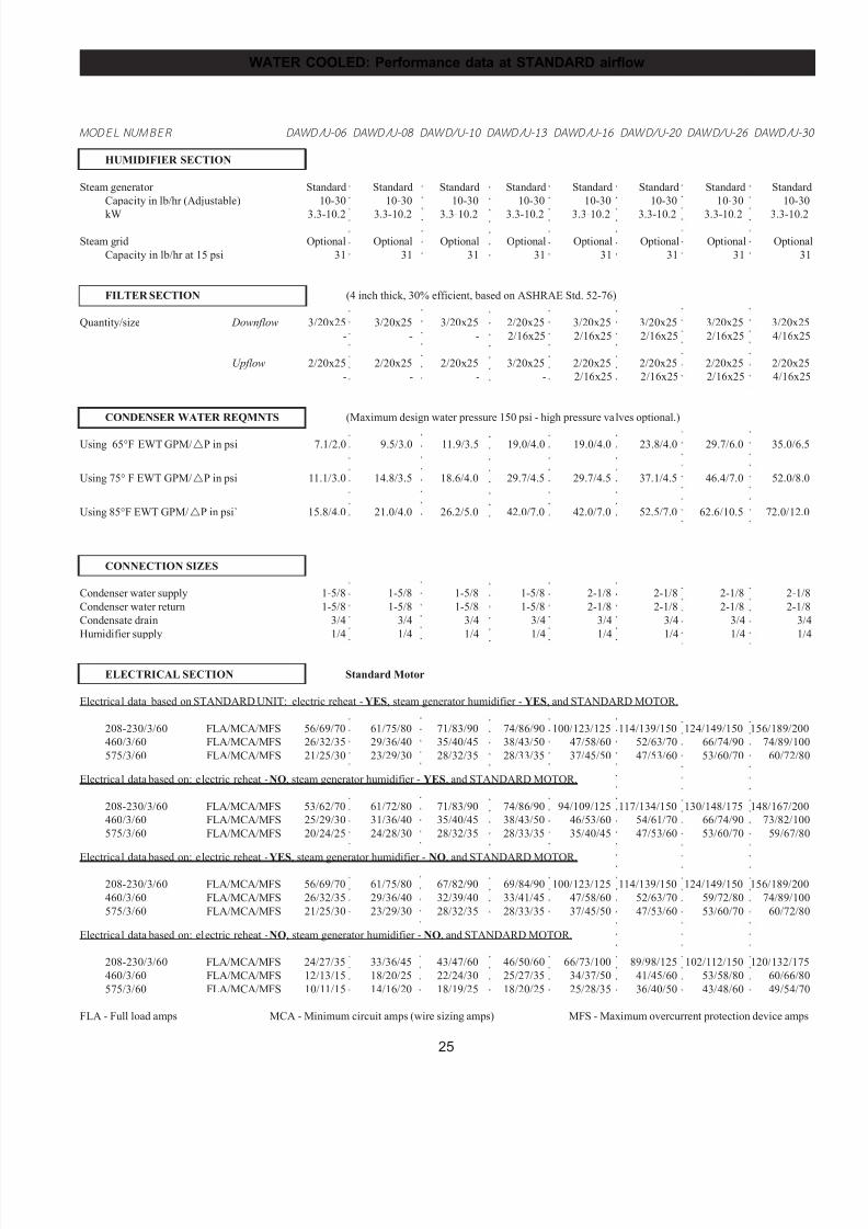
WATER COOLED: Performance data at STANDARD airflow
○
○
○
○
○
○
○
○
○
○
○
○
○
○
○
○
○
○
○
○
○
○
○
○
○
○
○
○
○
○
○
○
○
○
○
○
○
○
○
○
○
○
○
○
○
○
○
○
○
○
○
○
○
○
○
○
○
○
○
○
○
○
○
○
○
○
○
○
○
○
○
○
○
○
○
○
○
○
○
○
○
○
○
○
○
○
○
○
○
○
○
○
○
○
○
○
○
○
○
○
○
○
○
○
○
○
○
○
○
○
○
○
○
○
○
○
○
○
○
○
○
○
○
○
○
○
○
○
○
○
○
○
○
○
○
○
○
○
○
○
○
○
○
○
○
○
○
○
○
○
○
○
○
○
○
○
○
○
○
○
○
○
○
○
○
○
○
○
○
○
○
○
○
○
○
○
○
○
○
○
○
○
○
○
○
○
○
○
○
○
○
○
○
○
○
○
○
○
○
○
○
○
○
○
○
○
○
○
○
○
○
○
○
○
○
○
○
○
○
○
○
○
○
○
○
○
○
○
○
○
○
○
○
○
○
○
○
○
○
○
○
○
○
○
○
○
○
○
○
○
○
○
○
○
○
○
○
○
○
○
○
○
○
○
○
○
○
○
○
○
○
○
○
○
○
○
○
○
○
○
○
○
○
○
○
○
○
○
○
○
○
○
○
○
○
○
○
○
○
○
○
○
○
○
○
○
○
○
○
○
○
○
○
○
○
○
○
○
○
○
○
○
○
○
○
○
○
○
○
○
○
○
○
○
○
○
○
○
○
○
○
○
○
○
○
○
○
○
○
○
○
○
○
○
○
○
○
○
○
○
○
○
○
○
○
○
○
○
○
○
○
○
○
○
○
○
○
○
○
○
○
○
○
○
○
○
○
○
○
○
○
○
○
○
○
○
○
○
○
○
○
○
○
○
○
○
○
○
○
○
○
○
○
○
○
○
○
○
○
○
○
○
○
○
○
○
○
○
○
○
○
○
○
○
MODEL NUM BER DAWD/U-06 DAWD/U-08 DAWD/U-10 DAWD/U-13 DAWD/U-16 DAWD/U-20 DAWD/U-26 DAWD/U-30
HUMIDIFIER SECTION
Steam generator Standard Standard Standard Standard Standard Standard Standard Standard
Capacity in lb/hr (Adjustable) 10-30 10-30 10-30 10-30 10-30 10-30 10-30 10-30
kW 3.3-10.2 3.3-10.2 3.3-10.2 3.3-10.2 3.3-10.2 3.3-10.2 3.3-10.2 3.3-10.2
Steam grid Optional Optional Optional Optional Optional Optional Optional Optional
Capacity in lb/hr at 15 psi 31 31 31 31 31 31 31 31
FILTER SECTION (4 inch thick, 30% efficient, based on ASHRAE Std. 52-76)
Quantity/size Downflow 3/20x25 3/20x25 3/20x25 2/20x25 3/20x25 3/20x25 3/20x25 3/20x25
- - - 2/16x25 2/16x25 2/16x25 2/16x25 4/16x25
Upflow 2/20x25 2/20x25 2/20x25 3/20x25 2/20x25 2/20x25 2/20x25 2/20x25
- - - - 2/16x25 2/16x25 2/16x25 4/16x25
CONDENSER WATER REQMNTS (Maximum design water pressure 150 psi - high pressure valves optional.)
Using 65°F EWT GPM/!P in psi 7.1/2.0 9.5/3.0 11.9/3.5 19.0/4.0 19.0/4.0 23.8/4.0 29.7/6.0 35.0/6.5
Using 75° F EWT GPM/!P in psi 11.1/3.0 14.8/3.5 18.6/4.0 29.7/4.5 29.7/4.5 37.1/4.5 46.4/7.0 52.0/8.0
Using 85°F EWT GPM/!P in psi` 15.8/4.0 21.0/4.0 26.2/5.0 42.0/7.0 42.0/7.0 52.5/7.0 62.6/10.5 72.0/12.0
CONNECTION SIZES
Condenser water supply 1-5/8 1-5/8 1-5/8 1-5/8 2-1/8 2-1/8 2-1/8 2-1/8
Condenser water return 1-5/8 1-5/8 1-5/8 1-5/8 2-1/8 2-1/8 2-1/8 2-1/8
Condensate drain 3/4 3/4 3/4 3/4 3/4 3/4 3/4 3/4
Humidifier supply 1/4 1/4 1/4 1/4 1/4 1/4 1/4 1/4
ELECTRICAL SECTION Standard Motor
Electrical data based on STANDARD UNIT: electric reheat - YES, steam generator humidifier - YES, and STANDARD MOTOR.
208-230/3/60 FLA/MCA/MFS 56/69/70 61/75/80 71/83/90 74/86/90 100/123/125 114/139/150 124/149/150 156/189/200
460/3/60 FLA/MCA/MFS 26/32/35 29/36/40 35/40/45 38/43/50 47/58/60 52/63/70 66/74/90 74/89/100
575/3/60 FLA/MCA/MFS 21/25/30 23/29/30 28/32/35 28/33/35 37/45/50 47/53/60 53/60/70 60/72/80
Electrical data based on: electric reheat - NO, steam generator humidifier - YES, and STANDARD MOTOR.
208-230/3/60 FLA/MCA/MFS 53/62/70 61/72/80 71/83/90 74/86/90 94/109/125 117/134/150 130/148/175 148/167/200
460/3/60 FLA/MCA/MFS 25/29/30 31/36/40 35/40/45 38/43/50 46/53/60 54/61/70 66/74/90 73/82/100
575/3/60 FLA/MCA/MFS 20/24/25 24/28/30 28/32/35 28/33/35 35/40/45 47/53/60 53/60/70 59/67/80
Electrical data based on: electric reheat - YES, steam generator humidifier - NO, and STANDARD MOTOR.
208-230/3/60 FLA/MCA/MFS 56/69/70 61/75/80 67/82/90 69/84/90 100/123/125 114/139/150 124/149/150 156/189/200
460/3/60 FLA/MCA/MFS 26/32/35 29/36/40 32/39/40 33/41/45 47/58/60 52/63/70 59/72/80 74/89/100
575/3/60 FLA/MCA/MFS 21/25/30 23/29/30 28/32/35 28/33/35 37/45/50 47/53/60 53/60/70 60/72/80
Electrical data based on: electric reheat - NO, steam generator humidifier - NO, and STANDARD MOTOR.
208-230/3/60 FLA/MCA/MFS 24/27/35 33/36/45 43/47/60 46/50/60 66/73/100 89/98/125 102/112/150 120/132/175
460/3/60 FLA/MCA/MFS 12/13/15 18/20/25 22/24/30 25/27/35 34/37/50 41/45/60 53/58/80 60/66/80
575/3/60 FLA/MCA/MFS 10/11/15 14/16/20 18/19/25 18/20/25 25/28/35 36/40/50 43/48/60 49/54/70
FLA - Full load amps MCA - Minimum circuit amps (wire sizing amps) MFS - Maximum overcurrent protection device amps
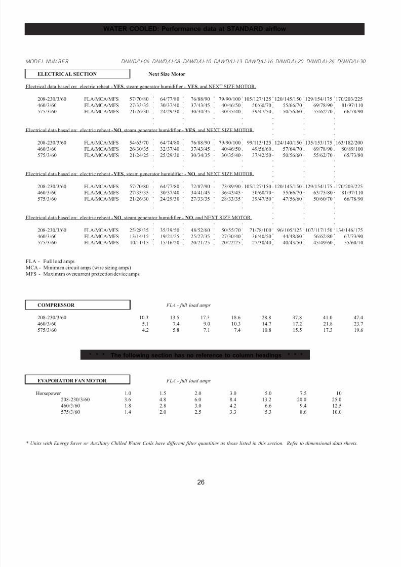
7/24/2019 DATA AIRE
http://slidepdf.com/reader/full/data-aire 26/76
26
WATER COOLED: Performance data at STANDARD airflow
○
○
○
○
○
○
○
○
○
○
○
○
○
○
○
○
○
○
○
○
○
○
○
○
○
○
○
○
○
○
○
○
○
○
○
○
○
○
○
○
○
○
○
○
○
○
○
○
○
○
○
○
○
○
○
○
○
○
○
○
○
○
○
○
○
○
○
○
○
○
○
○
○
○
○
○
○
○
○
○
○
○
○
○
○
○
○
○
○
○
○
○
○
○
○
○
○
○
○
○
○
○
○
○
○
○
○
○
○
○
○
○
○
○
○
○
○
○
○
○
○
○
○
○
○
○
○
○
○
○
○
○
○
○
○
○
○
○
○
○
○
○
○
○
○
○
○
○
○
○
○
○
○
○
○
○
○
○
○
○
○
○
○
○
○
○
○
○
○
○
○
○
○
○
○
○
○
○
○
○
○
○
○
○
○
○
○
○
○
○
○
○
○
○
○
○
○
○
○
○
○
○
○
MODEL NUM BER DAWD/U-06 DAWD/U-08 DAWD/U-10 DAWD/U-13 DAWD/U-16 DAWD/U-20 DAWD/U-26 DAWD/U-30
ELECTRICAL SECTION Next Size Motor
Electrical data based on: electric reheat - YES, steam generator humidifier - YES, and NEXT SIZE MOTOR.
208-230/3/60 FLA/MCA/MFS 57/70/80 64/77/80 76/88/90 79/90/100 105/127/125 120/145/150 129/154/175 170/203/225460/3/60 FLA/MCA/MFS 27/33/35 30/37/40 37/43/45 40/46/50 50/60/70 55/66/70 69/78/90 81/97/110
575/3/60 FLA/MCA/MFS 21/26/30 24/29/30 30/34/35 30/35/40 39/47/50 50/56/60 55/62/70 66/78/90
Electrical data based on: electric reheat - NO, steam generator humidifier - YES, and NEXT SIZE MOTOR.
208-230/3/60 FLA/MCA/MFS 54/63/70 64/74/80 76/88/90 79/90/100 99/113/125 124/140/150 135/153/175 163/182/200
460/3/60 FLA/MCA/MFS 26/30/35 32/37/40 37/43/45 40/46/50 49/56/60 57/64/70 69/78/90 80/89/100
575/3/60 FLA/MCA/MFS 21/24/25 25/29/30 30/34/35 30/35/40 37/42/50 50/56/60 55/62/70 65/73/80
Electrical data based on: electric reheat - YES, steam generator humidifier - NO, and NEXT SIZE MOTOR.
208-230/3/60 FLA/MCA/MFS 57/70/80 64/77/80 72/87/90 73/89/90 105/127/150 120/145/150 129/154/175 170/203/225
460/3/60 FLA/MCA/MFS 27/33/35 30/37/40 34/41/45 36/43/45 50/60/70 55/66/70 63/75/80 81/97/110
575/3/60 FLA/MCA/MFS 21/26/30 24/29/30 27/33/35 28/33/35 39/47/50 47/56/60 50/60/70 66/78/90
Electrical data based on: electric reheat - NO, steam generator humidifier - NO, and NEXT SIZE MOTOR.
208-230/3/60 FLA/MCA/MFS 25/28/35 35/39/50 48/52/60 50/55/70 71/78/100 96/105/125 107/117/150 134/146/175
460/3/60 FLA/MCA/MFS 13/14/15 19/21/25 25/27/35 27/30/40 36/40/50 44/48/60 56/62/80 67/73/90
575/3/60 FLA/MCA/MFS 10/11/15 15/16/20 20/21/25 20/22/25 27/30/40 40/43/50 45/49/60 55/60/70
FLA - Full load amps
MCA - Minimum circuit amps (wire sizing amps)
MFS - Maximum overcurrent protection device amps
COMPRESSOR FLA - full load amps
208-230/3/60 10.3 13.5 17.3 18.6 28.8 37.8 41.0 47.4
460/3/60 5.1 7.4 9.0 10.3 14.7 17.2 21.8 23.7
575/3/60 4.2 5.8 7.1 7.4 10.8 15.5 17.3 19.6
* * * The following section has no reference to column headings * * *
EVAPORATOR FAN MOTOR FLA - full load amps
Horsepower 1.0 1.5 2.0 3.0 5.0 7.5 10
208-230/3/60 3.6 4.8 6.0 8.4 13.2 20.0 25.0
460/3/60 1.8 2.8 3.0 4.2 6.6 9.4 12.5
575/3/60 1.4 2.0 2.5 3.3 5.3 8.6 10.0
* Units with Energy Saver or Auxiliary Chilled Water Coils have different filter quantities as those listed in this section. Refer to dimensional data sheets.
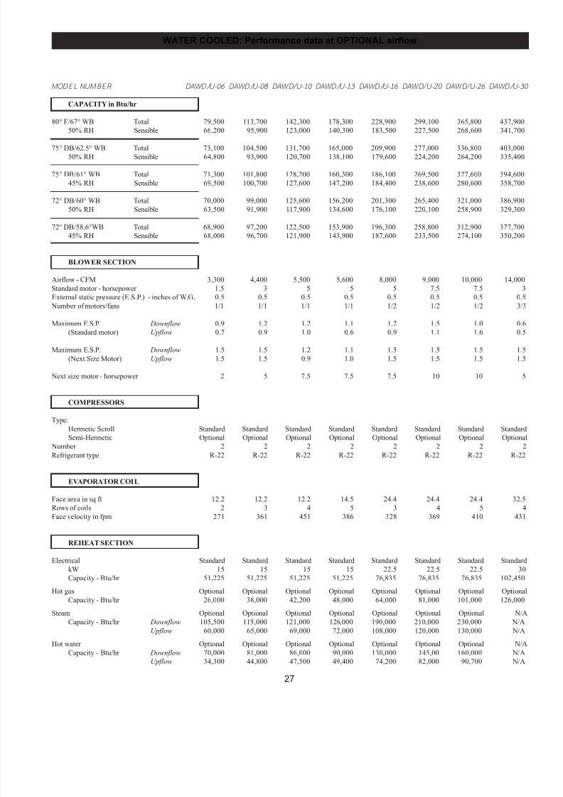
7/24/2019 DATA AIRE
http://slidepdf.com/reader/full/data-aire 27/76
27
WATER COOLED: Performance data at OPTIONAL airflow
MODEL NUM BER DAWD/U-06 DAWD/U-08 DAWD/U-10 DAWD/U-13 DAWD/U-16 DAWD/U-20 DAWD/U-26 DAWD/U-30
CAPACITY in Btu/hr
80° F/67° WB Total 79,500 113,700 142,300 178,300 228,900 299,100 365,800 437,900
50% RH Sensible 66,200 95,900 123,000 140,300 183,500 227,500 268,600 341,700
75° DB/62.5° WB Total 73,100 104,500 131,700 165,000 209,900 277,000 336,800 403,000
50% RH Sensible 64,800 93,900 120,700 138,100 179,600 224,200 264,200 335,400
75° DB/61° WB Total 71,300 101,800 128,200 160,300 186,100 269,500 327,600 394,600
45% RH Sensible 69,500 100,700 127,600 147,200 184,400 238,600 280,600 358,700
72° DB/60° WB Total 70,000 99,000 125,600 156,200 201,300 265,400 321,000 386,900
50% RH Sensible 63,500 91,900 117,900 134,600 176,100 220,100 258,900 329,300
72° DB/58.6°WB Total 68,900 97,200 122,500 153,900 196,300 258,800 312,900 377,700
45% RH Sensible 68,000 96,700 121,900 143,900 187,600 233,500 274,100 350,200
BLOWER SECTION
Airflow - CFM 3,300 4,400 5,500 5,600 8,000 9,000 10,000 14,000Standard motor - horsepower 1.5 3 5 5 5 7.5 7.5 3
External static pressure (E.S.P.) - inches of W.G. 0.5 0.5 0.5 0.5 0.5 0.5 0.5 0.5
Number of motors/fans 1/1 1/1 1/1 1/1 1/2 1/2 1/2 3/3
Maximum E.S.P. Downflow 0.9 1.2 1.2 1.1 1.2 1.5 1.0 0.6
(Standard motor) Upflow 0.7 0.9 1.0 0.6 0.9 1.1 1.6 0.5
Maximum E.S.P. Downflow 1.5 1.5 1.2 1.1 1.5 1.5 1.5 1.5
(Next Size Motor) Upflow 1.5 1.5 0.9 1.0 1.5 1.5 1.5 1.5
Next size motor - horsepower 2 5 7.5 7.5 7.5 10 10 5
COMPRESSORS
Type:Hermetic Scroll Standard Standard Standard Standard Standard Standard Standard Standard
Semi-Hermetic Optional Optional Optional Optional Optional Optional Optional Optional
Number 2 2 2 2 2 2 2 2
Refrigerant type R-22 R-22 R-22 R-22 R-22 R-22 R-22 R-22
EVAPORATOR COIL
Face area in sq ft 12.2 12.2 12.2 14.5 24.4 24.4 24.4 32.5
Rows of coils 2 3 4 5 3 4 5 4
Face velocity in fpm 271 361 451 386 328 369 410 431
REHEAT SECTION
Electrical Standard Standard Standard Standard Standard Standard Standard StandardkW 15 15 15 15 22.5 22.5 22.5 30
Capacity - Btu/hr 51,225 51,225 51,225 51,225 76,835 76,835 76,835 102,450
Hot gas Optional Optional Optional Optional Optional Optional Optional Optional
Capacity - Btu/hr 26,000 38,000 42,200 48,000 64,000 81,000 101,000 126,000
Steam Optional Optional Optional Optional Optional Optional Optional N/A
Capacity - Btu/hr Downflow 105,500 115,000 121,000 126,000 190,000 210,000 230,000 N/A
Upflow 60,000 65,000 69,000 72,000 108,000 120,000 130,000 N/A
Hot water Optional Optional Optional Optional Optional Optional Optional N/A
Capacity - Btu/hr Downflow 70,000 81,000 86,000 90,000 130,000 145,00 160,000 N/A
Upflow 34,300 44,800 47,500 49,400 74,200 82,000 90,700 N/A
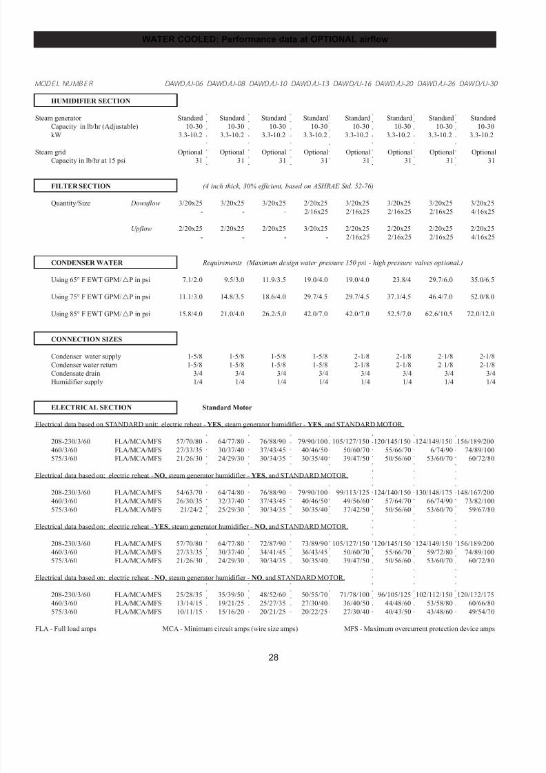
7/24/2019 DATA AIRE
http://slidepdf.com/reader/full/data-aire 28/76
28
WATER COOLED: Performance data at OPTIONAL airflow
○
○
○
○
○
○
○
○
○
○
○
○
○
○
○
○
○
○
○
○
○
○
○
○
○
○
○
○
○
○
○
○
○
○
○
○
○
○
○
○
○
○
○
○
○
○
○
○
○
○
○
○
○
○
○
○
○
○
○
○
○
○
○
○
○
○
○
○
○
○
○
○
○
○
○
○
○
○
○
○
○
○
○
○
○
○
○
○
○
○
○
○
○
○
○
○
○
○
○
○
○
○
○
○
○
○
○
○
○
○
○
○
○
○
○
○
○
○
○
○
○
○
○
○
○
○
○
○
○
○
○
○
○
○
○
○
○
○
○
○
○
○
○
○
○
○
○
○
○
○
○
○
○
○
○
○
○
○
○
○
○
○
○
○
○
○
○
○
○
○
○
○
○
○
○
○
○
○
○
○
○
○
○
○
○
○
○
○
○
○
○
○
○
○
○
○
○
○
○
○
○
○
○
○
○
○
○
○
○
○
○
○
○
○
○
○
○
○
○
○
○
○
○
○
○
○
○
○
○
○
○
○
○
○
○
○
○
○
○
○
○
○
○
○
○
○
○
○
○
○
○
○
○
○
○
○
○
○
○
○
○
○
○
○
○
○
○
○
○
○
○
○
○
○
○
○
○
○
○
○
○
○
○
○
○
○
○
○
○
○
○
○
○
○
○
○
○
○
○
○
○
○
○
○
○
○
○
○
○
○
○
○
○
○
○
○
○
○
○
○
○
○
○
○
○
○
○
○
○
○
○
○
○
○
○
○
○
○
○
○
○
○
○
○
○
○
○
○
○
○
○
○
○
○
○
○
○
○
○
○
○
○
○
○
○
○
○
○
○
○
○
○
○
○
○
○
○
○
○
○
○
○
○
○
○
○
○
○
○
○
○
○
○
○
○
○
○
○
○
○
○
○
○
○
○
○
○
○
○
○
○
○
○
○
○
○
○
○
○
○
○
○
○
○
○
○
○
○
○
○
○
○
○
○
○
○
○
○
○
○
○
○
○
○
○
○
○
○
○
○
○
○
○
○
○
○
○
○
○
○
○
○
○
○
○
○
○
○
○
○
○
○
○
○
○
○
○
○
○
○
○
○
○
○
○
○
○
○
○
○
○
○
○
○
○
○
○
MODEL NUM BER DAWD/U-06 DAWD/U-08 DAWD/U-10 DAWD/U-13 DAWD/U-16 DAWD/U-20 DAWD/U-26 DAWD/U-30
HUMIDIFIER SECTION
Steam generator Standard Standard Standard Standard Standard Standard Standard Standard
Capacity in lb/hr (Adjustable) 10-30 10-30 10-30 10-30 10-30 10-30 10-30 10-30
kW 3.3-10.2 3.3-10.2 3.3-10.2 3.3-10.2 3.3-10.2 3.3-10.2 3.3-10.2 3.3-10.2
Steam grid Optional Optional Optional Optional Optional Optional Optional Optional
Capacity in lb/hr at 15 psi 31 31 31 31 31 31 31 31
FILTER SECTION (4 inch thick, 30% efficient, based on ASHRAE Std. 52-76)
Quantity/Size Downflow 3/20x25 3/20x25 3/20x25 2/20x25 3/20x25 3/20x25 3/20x25 3/20x25
- - - 2/16x25 2/16x25 2/16x25 2/16x25 4/16x25
Upflow 2/20x25 2/20x25 2/20x25 3/20x25 2/20x25 2/20x25 2/20x25 2/20x25
- - - - 2/16x25 2/16x25 2/16x25 4/16x25
CONDENSER WATER Requirements (Maximum design water pressure 150 psi - high pressure valves optional.)
Using 65° F EWT GPM/!P in psi 7.1/2.0 9.5/3.0 11.9/3.5 19.0/4.0 19.0/4.0 23.8/4 29.7/6.0 35.0/6.5
Using 75° F EWT GPM/!P in psi 11.1/3.0 14.8/3.5 18.6/4.0 29.7/4.5 29.7/4.5 37.1/4.5 46.4/7.0 52.0/8.0
Using 85° F EWT GPM/!P in psi 15.8/4.0 21.0/4.0 26.2/5.0 42.0/7.0 42.0/7.0 52.5/7.0 62.6/10.5 72.0/12.0
CONNECTION SIZES
Condenser water supply 1-5/8 1-5/8 1-5/8 1-5/8 2-1/8 2-1/8 2-1/8 2-1/8
Condenser water return 1-5/8 1-5/8 1-5/8 1-5/8 2-1/8 2-1/8 2-1/8 2-1/8
Condensate drain 3/4 3/4 3/4 3/4 3/4 3/4 3/4 3/4
Humidifier supply 1/4 1/4 1/4 1/4 1/4 1/4 1/4 1/4
ELECTRICAL SECTION Standard Motor
Electrical data based on STANDARD unit: electric reheat - YES, steam generator humidifier - YES, and STANDARD MOTOR.
208-230/3/60 FLA/MCA/MFS 57/70/80 64/77/80 76/88/90 79/90/100 105/127/150 120/145/150 124/149/150 156/189/200
460/3/60 FLA/MCA/MFS 27/33/35 30/37/40 37/43/45 40/46/50 50/60/70 55/66/70 6/74/90 74/89/100
575/3/60 FLA/MCA/MFS 21/26/30 24/29/30 30/34/35 30/35/40 39/47/50 50/56/60 53/60/70 60/72/80
Electrical data based on: electric reheat - NO, steam generator humidifier - YES, and STANDARD MOTOR.
208-230/3/60 FLA/MCA/MFS 54/63/70 64/74/80 76/88/90 79/90/100 99/113/125 124/140/150 130/148/175 148/167/200
460/3/60 FLA/MCA/MFS 26/30/35 32/37/40 37/43/45 40/46/50 49/56/60 57/64/70 66/74/90 73/82/100
575/3/60 FLA/MCA/MFS 21/24/2 25/29/30 30/34/35 30/35/40 37/42/50 50/56/60 53/60/70 59/67/80
Electrical data based on: electric reheat - YES, steam generator humidifier - NO, and STANDARD MOTOR.
208-230/3/60 FLA/MCA/MFS 57/70/80 64/77/80 72/87/90 73/89/90 105/127/150 120/145/150 124/149/150 156/189/200460/3/60 FLA/MCA/MFS 27/33/35 30/37/40 34/41/45 36/43/45 50/60/70 55/66/70 59/72/80 74/89/100
575/3/60 FLA/MCA/MFS 21/26/30 24/29/30 30/34/35 30/35/40 39/47/50 50/56/60 53/60/70 60/72/80
Electrical data based on: electric reheat - NO, steam generator humidifier - NO, and STANDARD MOTOR.
208-230/3/60 FLA/MCA/MFS 25/28/35 35/39/50 48/52/60 50/55/70 71/78/100 96/105/125 102/112/150 120/132/175
460/3/60 FLA/MCA/MFS 13/14/15 19/21/25 25/27/35 27/30/40 36/40/50 44/48/60 53/58/80 60/66/80
575/3/60 FLA/MCA/MFS 10/11/15 15/16/20 20/21/25 20/22/25 27/30/40 40/43/50 43/48/60 49/54/70
FLA - Full load amps MCA - Minimum circuit amps (wire size amps) MFS - Maximum overcurrent protection device amps
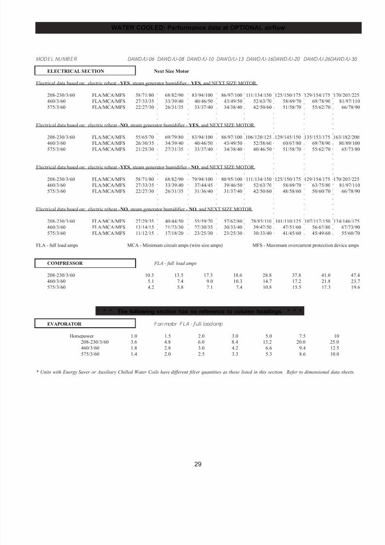
7/24/2019 DATA AIRE
http://slidepdf.com/reader/full/data-aire 29/76
29
WATER COOLED: Performance data at OPTIONAL airflow
○
○
○
○
○
○
○
○
○
○
○
○
○
○
○
○
○
○
○
○
○
○
○
○
○
○
○
○
○
○
○
○
○
○
○
○
○
○
○
○
○
○
○
○
○
○
○
○
○
○
○
○
○
○
○
○
○
○
○
○
○
○
○
○
○
○
○
○
○
○
○
○
○
○
○
○
○
○
○
○
○
○
○
○
○
○
○
○
○
○
○
○
○
○
○
○
○
○
○
○
○
○
○
○
○
○
○
○
○
○
○
○
○
○
○
○
○
○
○
○
○
○
○
○
○
○
○
○
○
○
○
○
○
○
○
○
○
○
○
○
○
○
○
○
○
○
○
○
○
○
○
○
○
○
○
○
○
○
○
○
○
○
○
○
○
○
○
○
○
○
○
○
○
○
○
○
○
○
○
○
○
○
○
○
○
○
○
○
○
○
○
○
○
○
○
○
○
○
○
○
○
○
○
MODEL NUM BER DAWD/U-06 DAWD/U-08 DAWD/U-10 DAWD/U-13 DAWD/U-16DAWD/U-20 DAWD/U-26DAWD/U-30
ELECTRICAL SECTION Next Size Motor
Electrical data based on: electric reheat - YES, steam generator humidifier - YES, and NEXT SIZE MOTOR.
208-230/3/60 FLA/MCA/MFS 58/71/80 68/82/90 83/94/100 86/97/100 111/134/150 125/150/175 129/154/175 170/203/225460/3/60 FLA/MCA/MFS 27/33/35 33/39/40 40/46/50 43/49/50 52/63/70 58/69/70 69/78/90 81/97/110
575/3/60 FLA/MCA/MFS 22/27/30 26/31/35 33/37/40 34/38/40 42/50/60 51/58/70 55/62/70 66/78/90
Electrical data based on: electric reheat - NO, steam generator humidifier - YES, and NEXT SIZE MOTOR.
208-230/3/60 FLA/MCA/MFS 55/65/70 69/79/80 83/94/100 86/97/100 106/120/125 129/145/150 135/153/175 163/182/200
460/3/60 FLA/MCA/MFS 26/30/35 34/39/40 40/46/50 43/49/50 52/58/60 60/67/80 69/78/90 80/89/100
575/3/60 FLA/MCA/MFS 21/25/30 27/31/35 33/37/40 34/38/40 40/46/50 51/58/70 55/62/70 65/73/80
Electrical data based on: electric reheat - YES, steam generator humidifier - NO, and NEXT SIZE MOTOR.
208-230/3/60 FLA/MCA/MFS 58/71/80 68/82/90 79/94/100 80/95/100 111/134/150 125/150/175 129/154/175 170/203/225
460/3/60 FLA/MCA/MFS 27/33/35 33/39/40 37/44/45 39/46/50 52/63/70 58/69/70 63/75/80 81/97/110
575/3/60 FLA/MCA/MFS 22/27/30 26/31/35 31/36/40 31/37/40 42/50/60 48/58/60 50/60/70 66/78/90
Electrical data based on: electric reheat - NO, steam generator humidifier - NO, and NEXT SIZE MOTOR.
208-230/3/60 FLA/MCA/MFS 27/29/35 40/44/50 55/59/70 57/62/80 78/85/110 101/110/125 107/117/150 134/146/175
460/3/60 FLA/MCA/MFS 13/14/15 21/23/30 27/30/35 30/33/40 39/42/50 47/51/60 56/62/80 67/73/90
575/3/60 FLA/MCA/MFS 11/12/15 17/18/20 23/25/30 23/25/30 30/33/40 41/45/60 45/49/60 55/60/70
FLA - full load amps MCA - Minimum circuit amps (wire size amps) MFS - Maximum overcurrent protection device amps
COMPRESSOR FLA - full load amps
208-230/3/60 10.3 13.5 17.3 18.6 28.8 37.8 41.0 47.4
460/3/60 5.1 7.4 9.0 10.3 14.7 17.2 21.8 23.7
575/3/60 4.2 5.8 7.1 7.4 10.8 15.5 17.3 19.6
* * * The following section has no reference to column headings * * *
EVAPORATOR Fan motor FL A - full load amp
Horsepower 1.0 1.5 2.0 3.0 5.0 7.5 10
208-230/3/60 3.6 4.8 6.0 8.4 13.2 20.0 25.0
460/3/60 1.8 2.8 3.0 4.2 6.6 9.4 12.5
575/3/60 1.4 2.0 2.5 3.3 5.3 8.6 10.0
* Units with Energy Saver or Auxiliary Chilled Water Coils have different filter quantities as those listed in this section. Refer to dimensional data sheets.
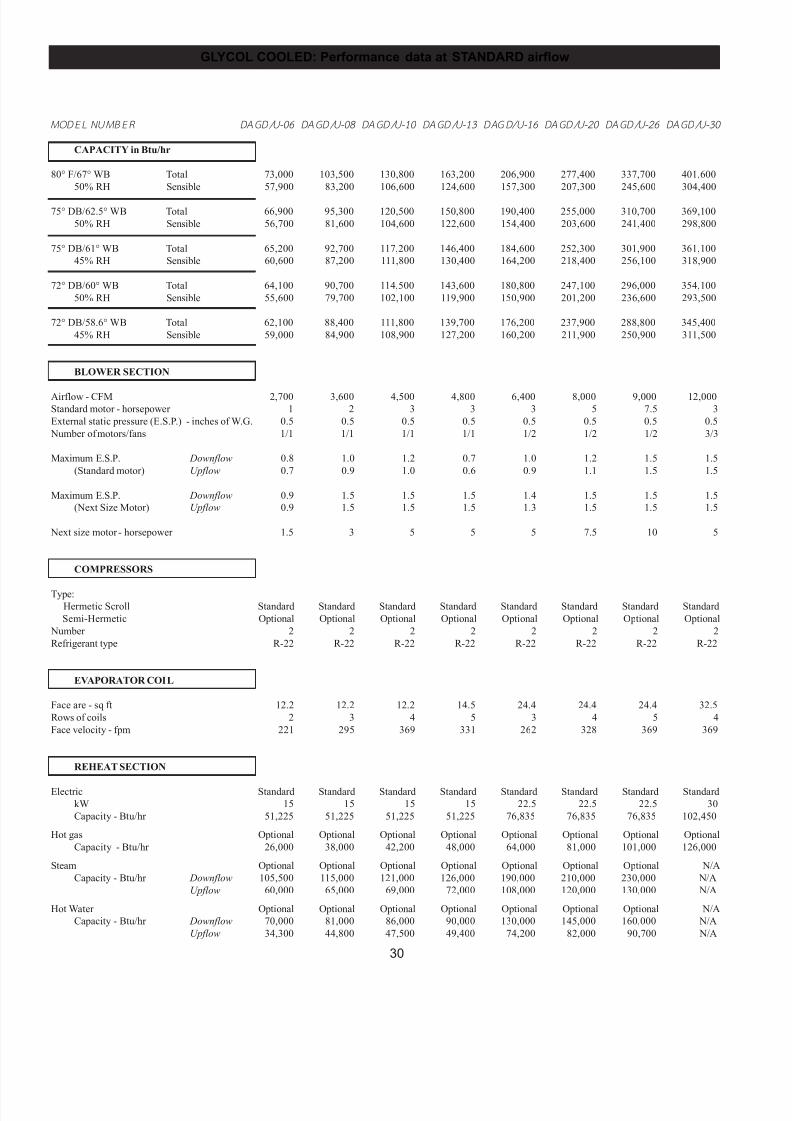
7/24/2019 DATA AIRE
http://slidepdf.com/reader/full/data-aire 30/76
30
M ODEL NUM BER DAGD/U-06 DAGD/U-08 DAGD/U-10 DAGD/U-13 DAGD/U-16 DAGD/U-20 DAGD/U-26 DAGD/U-30
CAPACITY in Btu/hr
80° F/67° WB Total 73,000 103,500 130,800 163,200 206,900 277,400 337,700 401,600
50% RH Sensible 57,900 83,200 106,600 124,600 157,300 207,300 245,600 304,400
75° DB/62.5° WB Total 66,900 95,300 120,500 150,800 190,400 255,000 310,700 369,100
50% RH Sensible 56,700 81,600 104,600 122,600 154,400 203,600 241,400 298,800
75° DB/61° WB Total 65,200 92,700 117,200 146,400 184,600 252,300 301,900 361,100
45% RH Sensible 60,600 87,200 111,800 130,400 164,200 218,400 256,100 318,900
72° DB/60° WB Total 64,100 90,700 114,500 143,600 180,800 247,100 296,000 354,100
50% RH Sensible 55,600 79,700 102,100 119,900 150,900 201,200 236,600 293,500
72° DB/58.6° WB Total 62,100 88,400 111,800 139,700 176,200 237,900 288,800 345,400
45% RH Sensible 59,000 84,900 108,900 127,200 160,200 211,900 250,900 311,500
BLOWER SECTION
Airflow - CFM 2,700 3,600 4,500 4,800 6,400 8,000 9,000 12,000
Standard motor - horsepower 1 2 3 3 3 5 7.5 3
External static pressure (E.S.P.) - inches of W.G. 0.5 0.5 0.5 0.5 0.5 0.5 0.5 0.5
Number of motors/fans 1/1 1/1 1/1 1/1 1/2 1/2 1/2 3/3
Maximum E.S.P. Downflow 0.8 1.0 1.2 0.7 1.0 1.2 1.5 1.5
(Standard motor) Upflow 0.7 0.9 1.0 0.6 0.9 1.1 1.5 1.5
Maximum E.S.P. Downflow 0.9 1.5 1.5 1.5 1.4 1.5 1.5 1.5
(Next Size Motor) Upflow 0.9 1.5 1.5 1.5 1.3 1.5 1.5 1.5
Next size motor - horsepower 1.5 3 5 5 5 7.5 10 5
COMPRESSORS
Type:
Hermetic Scroll Standard Standard Standard Standard Standard Standard Standard Standard
Semi-Hermetic Optional Optional Optional Optional Optional Optional Optional Optional
Number 2 2 2 2 2 2 2 2
Refrigerant type R-22 R-22 R-22 R-22 R-22 R-22 R-22 R-22
EVAPORATOR COIL
Face are - sq ft 12.2 12.2 12.2 14.5 24.4 24.4 24.4 32.5
Rows of coils 2 3 4 5 3 4 5 4
Face velocity - fpm 221 295 369 331 262 328 369 369
REHEAT SECTION
Electric Standard Standard Standard Standard Standard Standard Standard Standard
kW 15 15 15 15 22.5 22.5 22.5 30
Capacity - Btu/hr 51,225 51,225 51,225 51,225 76,835 76,835 76,835 102,450
Hot gas Optional Optional Optional Optional Optional Optional Optional Optional
Capacity - Btu/hr 26,000 38,000 42,200 48,000 64,000 81,000 101,000 126,000
Steam Optional Optional Optional Optional Optional Optional Optional N/A
Capacity - Btu/hr Downflow 105,500 115,000 121,000 126,000 190,000 210,000 230,000 N/A
Upflow 60,000 65,000 69,000 72,000 108,000 120,000 130,000 N/A
Hot Water Optional Optional Optional Optional Optional Optional Optional N/A
Capacity - Btu/hr Downflow 70,000 81,000 86,000 90,000 130,000 145,000 160,000 N/A
Upflow 34,300 44,800 47,500 49,400 74,200 82,000 90,700 N/A
GLYCOL COOLED: Performance data at STANDARD airflow
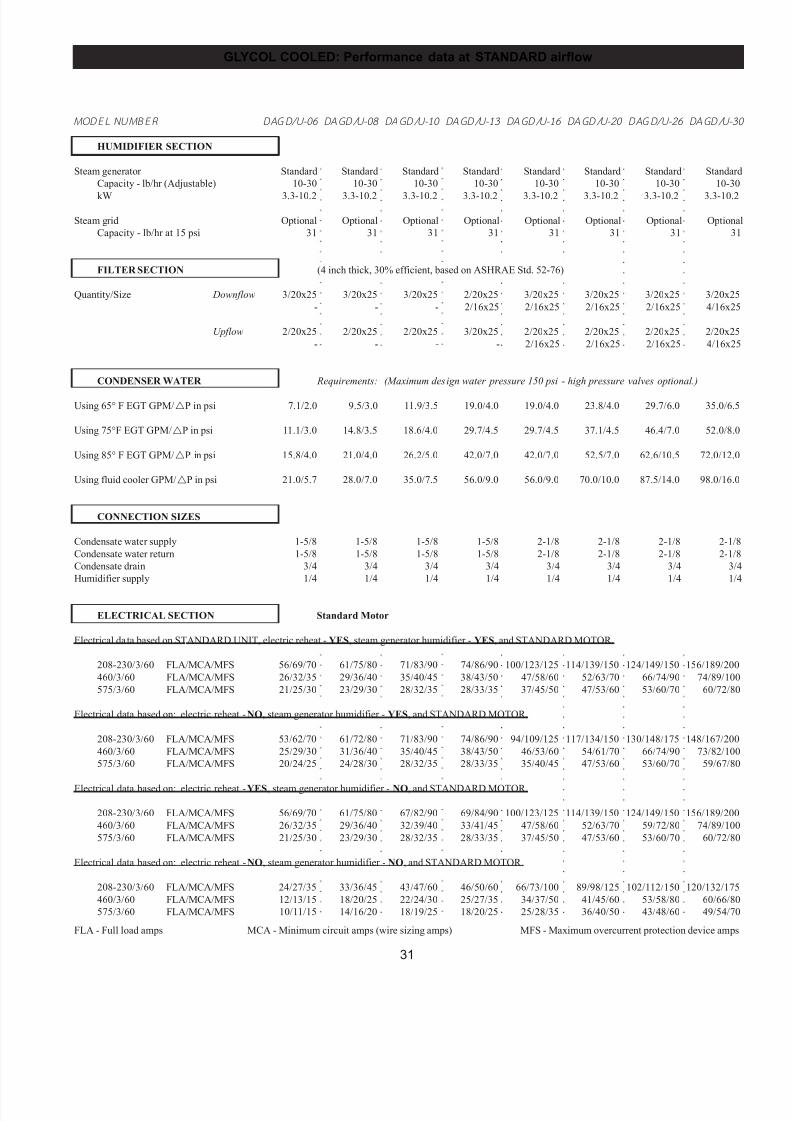
7/24/2019 DATA AIRE
http://slidepdf.com/reader/full/data-aire 31/76
31
○
○
○
○
○
○
○
○
○
○
○
○
○
○
○
○
○
○
○
○
○
○
○
○
○
○
○
○
○
○
○
○
○
○
○
○
○
○
○
○
○
○
○
○
○
○
○
○
○
○
○
○
○
○
○
○
○
○
○
○
○
○
○
○
○
○
○
○
○
○
○
○
○
○
○
○
○
○
○
○
○
○
○
○
○
○
○
○
○
○
○
○
○
○
○
○
○
○
○
○
○
○
○
○
○
○
○
○
○
○
○
○
○
○
○
○
○
○
○
○
○
○
○
○
○
○
○
○
○
○
○
○
○
○
○
○
○
○
○
○
○
○
○
○
○
○
○
○
○
○
○
○
○
○
○
○
○
○
○
○
○
○
○
○
○
○
○
○
○
○
○
○
○
○
○
○
○
○
○
○
○
○
○
○
○
○
○
○
○
○
○
○
○
○
○
○
○
○
○
○
○
○
○
○
○
○
○
○
○
○
○
○
○
○
○
○
○
○
○
GLYCOL COOLED: Performance data at STANDARD airflow
○
○
○
○
○
○
○
○
○
○
○
○
○
○
○
○
○
○
○
○
○
○
○
○
○
○
○
○
○
○
○
○
○
○
○
○
○
○
○
○
○
○
○
○
○
○
○
○
○
○
○
○
○
○
○
○
○
○
○
○
○
○
○
○
○
○
○
○
○
○
○
○
○
○
○
○
○
○
○
○
○
○
○
○
○
○
○
○
○
○
○
○
○
○
○
○
○
○
○
○
○
○
○
○
○
○
○
○
○
○
○
○
○
○
○
○
○
○
○
○
○
○
○
○
○
○
○
○
○
○
○
○
○
○
○
○
○
○
○
○
○
○
○
○
○
○
○
○
○
○
○
○
○
○
○
○
○
○
○
○
○
○
○
○
○
○
○
○
○
○
○
○
○
○
○
○
○
○
○
○
○
○
○
○
○
○
○
○
○
○
○
○
○
○
○
○
○
○
○
○
○
○
○
○
○
○
○
○
○
○
○
○
○
○
○
○
○
○
○
○
○
○
○
○
○
○
○
○
○
○
○
○
○
○
○
○
○
○
○
○
○
○
○
○
○
○
○
○
○
○
○
○
○
○
○
○
○
○
○
○
○
○
○
○
○
○
○
○
○
○
○
○
○
○
○
○
○
○
○
○
○
○
○
○
○
○
○
○
○
○
○
○
M ODEL NUM BER DAGD/U-06 DAGD/U-08 DAGD/U-10 DAGD/U-13 DAGD/U-16 DAGD/U-20 DAGD/U-26 DAGD/U-3
HUMIDIFIER SECTION
Steam generator Standard Standard Standard Standard Standard Standard Standard Standard
Capacity - lb/hr (Adjustable) 10-30 10-30 10-30 10-30 10-30 10-30 10-30 10-30
kW 3.3-10.2 3.3-10.2 3.3-10.2 3.3-10.2 3.3-10.2 3.3-10.2 3.3-10.2 3.3-10.2
Steam grid Optional Optional Optional Optional Optional Optional Optional Optional
Capacity - lb/hr at 15 psi 31 31 31 31 31 31 31 31
FILTER SECTION (4 inch thick, 30% efficient, based on ASHRAE Std. 52-76)
Quantity/Size Downflow 3/20x25 3/20x25 3/20x25 2/20x25 3/20x25 3/20x25 3/20x25 3/20x25
- - - 2/16x25 2/16x25 2/16x25 2/16x25 4/16x25
Upflow 2/20x25 2/20x25 2/20x25 3/20x25 2/20x25 2/20x25 2/20x25 2/20x25
- - - - 2/16x25 2/16x25 2/16x25 4/16x25
CONDENSER WATER Requirements: (Maximum design water pressure 150 psi - high pressure valves optional.)
Using 65° F EGT GPM/!P in psi 7.1/2.0 9.5/3.0 11.9/3.5 19.0/4.0 19.0/4.0 23.8/4.0 29.7/6.0 35.0/6.5
Using 75°F EGT GPM/!P in psi 11.1/3.0 14.8/3.5 18.6/4.0 29.7/4.5 29.7/4.5 37.1/4.5 46.4/7.0 52.0/8.0
Using 85° F EGT GPM/!P in psi 15.8/4.0 21.0/4.0 26.2/5.0 42.0/7.0 42.0/7.0 52.5/7.0 62.6/10.5 72.0/12.0
Using fluid cooler GPM/!P in psi 21.0/5.7 28.0/7.0 35.0/7.5 56.0/9.0 56.0/9.0 70.0/10.0 87.5/14.0 98.0/16.0
CONNECTION SIZES
Condensate water supply 1-5/8 1-5/8 1-5/8 1-5/8 2-1/8 2-1/8 2-1/8 2-1/8
Condensate water return 1-5/8 1-5/8 1-5/8 1-5/8 2-1/8 2-1/8 2-1/8 2-1/8
Condensate drain 3/4 3/4 3/4 3/4 3/4 3/4 3/4 3/4
Humidifier supply 1/4 1/4 1/4 1/4 1/4 1/4 1/4 1/4
ELECTRICAL SECTION Standard Motor
Electrical data based on STANDARD UNIT, electric reheat - YES, steam generator humidifier - YES, and STANDARD MOTOR.
208-230/3/60 FLA/MCA/MFS 56/69/70 61/75/80 71/83/90 74/86/90 100/123/125 114/139/150 124/149/150 156/189/200
460/3/60 FLA/MCA/MFS 26/32/35 29/36/40 35/40/45 38/43/50 47/58/60 52/63/70 66/74/90 74/89/100
575/3/60 FLA/MCA/MFS 21/25/30 23/29/30 28/32/35 28/33/35 37/45/50 47/53/60 53/60/70 60/72/80
Electrical data based on: electric reheat - NO, steam generator humidifier - YES, and STANDARD MOTOR.
208-230/3/60 FLA/MCA/MFS 53/62/70 61/72/80 71/83/90 74/86/90 94/109/125 117/134/150 130/148/175 148/167/200
460/3/60 FLA/MCA/MFS 25/29/30 31/36/40 35/40/45 38/43/50 46/53/60 54/61/70 66/74/90 73/82/100
575/3/60 FLA/MCA/MFS 20/24/25 24/28/30 28/32/35 28/33/35 35/40/45 47/53/60 53/60/70 59/67/80
Electrical data based on: electric reheat - YES, steam generator humidifier - NO, and STANDARD MOTOR.
208-230/3/60 FLA/MCA/MFS 56/69/70 61/75/80 67/82/90 69/84/90 100/123/125 114/139/150 124/149/150 156/189/200
460/3/60 FLA/MCA/MFS 26/32/35 29/36/40 32/39/40 33/41/45 47/58/60 52/63/70 59/72/80 74/89/100
575/3/60 FLA/MCA/MFS 21/25/30 23/29/30 28/32/35 28/33/35 37/45/50 47/53/60 53/60/70 60/72/80
Electrical data based on: electric reheat - NO, steam generator humidifier - NO, and STANDARD MOTOR.
208-230/3/60 FLA/MCA/MFS 24/27/35 33/36/45 43/47/60 46/50/60 66/73/100 89/98/125 102/112/150 120/132/175
460/3/60 FLA/MCA/MFS 12/13/15 18/20/25 22/24/30 25/27/35 34/37/50 41/45/60 53/58/80 60/66/80
575/3/60 FLA/MCA/MFS 10/11/15 14/16/20 18/19/25 18/20/25 25/28/35 36/40/50 43/48/60 49/54/70
FLA - Full load amps MCA - Minimum circuit amps (wire sizing amps) MFS - Maximum overcurrent protection device amps
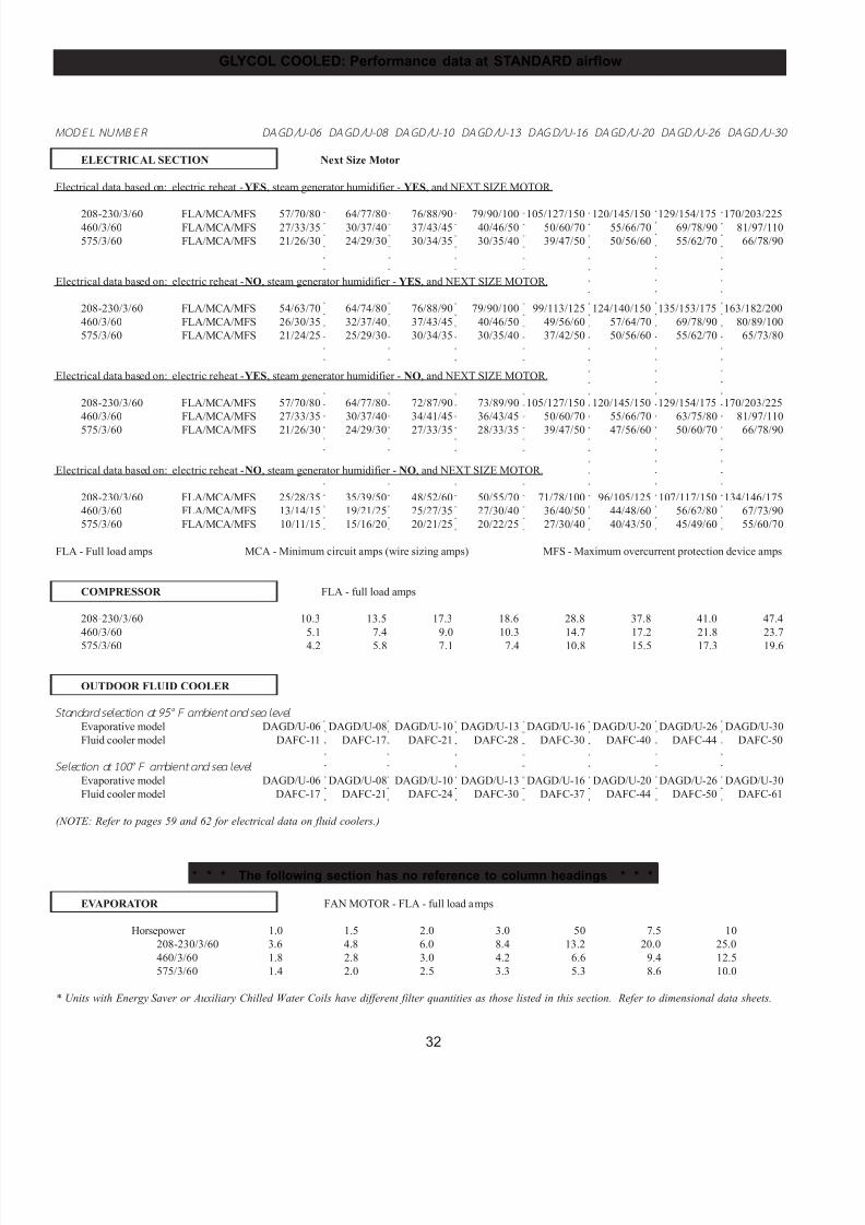
7/24/2019 DATA AIRE
http://slidepdf.com/reader/full/data-aire 32/76
32
GLYCOL COOLED: Performance data at STANDARD airflow
○
○
○
○
○
○
○
○
○
○
○
○
○
○
○
○
○
○
○
○
○
○
○
○
○
○
○
○
○
○
○
○
○
○
○
○
○
○
○
○
○
○
○
○
○
○
○
○
○
○
○
○
○
○
○
○
○
○
○
○
○
○
○
○
○
○
○
○
○
○
○
○
○
○
○
○
○
○
○
○
○
○
○
○
○
○
○
○
○
○
○
○
○
○
○
○
○
○
○
○
○
○
○
○
○
○
○
○
○
○
○
○
○
○
○
○
○
○
○
○
○
○
○
○
○
○
○
○
○
○
○
○
○
○
○
○
○
○
○
○
○
○
○
○
○
○
○
○
○
○
○
○
○
○
○
○
○
○
○
○
○
○
○
○
○
○
○
○
○
○
○
○
○
○
○
○
○
○
○
○
○
○
○
○
○
○
○
○
○
○
○
○
○
○
○
○
○
○
○
○
○
○
○
○
○
○
○
○
○
○
○
○
○
○
○
○
○
○
○
○
○
○
○
○
○
○
○
○
○
○
○
○
○
○
○
○
○
○
○
○
○
○
○
○
○
○
○
○
○
○
○
○
○
○
○
○
○
○
○
○
○
○
○
○
○
○
○
○
○
○
○
○
○
○
○
○
○
○
○
○
○
○
○
○
○
○
○
○
○
○
○
○
○
○
○
○
○
○
○
○
○
○
○
○
○
○
○
○
○
○
○
○
○
○
○
○
○
○
M ODEL NUM BER DAGD/U-06 DAGD/U-08 DAGD/U-10 DAGD/U-13 DAGD/U-16 DAGD/U-20 DAGD/U-26 DAGD/U-30
ELECTRICAL SECTION Next Size Motor
Electrical data based on: electric reheat - YES, steam generator humidifier - YES, and NEXT SIZE MOTOR.
208-230/3/60 FLA/MCA/MFS 57/70/80 64/77/80 76/88/90 79/90/100 105/127/150 120/145/150 129/154/175 170/203/225460/3/60 FLA/MCA/MFS 27/33/35 30/37/40 37/43/45 40/46/50 50/60/70 55/66/70 69/78/90 81/97/110
575/3/60 FLA/MCA/MFS 21/26/30 24/29/30 30/34/35 30/35/40 39/47/50 50/56/60 55/62/70 66/78/90
Electrical data based on: electric reheat - NO, steam generator humidifier - YES, and NEXT SIZE MOTOR.
208-230/3/60 FLA/MCA/MFS 54/63/70 64/74/80 76/88/90 79/90/100 99/113/125 124/140/150 135/153/175 163/182/200
460/3/60 FLA/MCA/MFS 26/30/35 32/37/40 37/43/45 40/46/50 49/56/60 57/64/70 69/78/90 80/89/100
575/3/60 FLA/MCA/MFS 21/24/25 25/29/30 30/34/35 30/35/40 37/42/50 50/56/60 55/62/70 65/73/80
Electrical data based on: electric reheat - YES, steam generator humidifier - NO, and NEXT SIZE MOTOR.
208-230/3/60 FLA/MCA/MFS 57/70/80 64/77/80 72/87/90 73/89/90 105/127/150 120/145/150 129/154/175 170/203/225
460/3/60 FLA/MCA/MFS 27/33/35 30/37/40 34/41/45 36/43/45 50/60/70 55/66/70 63/75/80 81/97/110
575/3/60 FLA/MCA/MFS 21/26/30 24/29/30 27/33/35 28/33/35 39/47/50 47/56/60 50/60/70 66/78/90
Electrical data based on: electric reheat - NO, steam generator humidifier - NO, and NEXT SIZE MOTOR.
208-230/3/60 FLA/MCA/MFS 25/28/35 35/39/50 48/52/60 50/55/70 71/78/100 96/105/125 107/117/150 134/146/175
460/3/60 FLA/MCA/MFS 13/14/15 19/21/25 25/27/35 27/30/40 36/40/50 44/48/60 56/62/80 67/73/90
575/3/60 FLA/MCA/MFS 10/11/15 15/16/20 20/21/25 20/22/25 27/30/40 40/43/50 45/49/60 55/60/70
FLA - Full load amps MCA - Minimum circuit amps (wire sizing amps) MFS - Maximum overcurrent protection device amps
COMPRESSOR FLA - full load amps
208-230/3/60 10.3 13.5 17.3 18.6 28.8 37.8 41.0 47.4
460/3/60 5.1 7.4 9.0 10.3 14.7 17.2 21.8 23.7
575/3/60 4.2 5.8 7.1 7.4 10.8 15.5 17.3 19.6
OUTDOOR FLUID COOLER
Standar d selecti on at 95°F ambient and sea level
Evaporative model DAGD/U-06 DAGD/U-08 DAGD/U-10 DAGD/U-13 DAGD/U-16 DAGD/U-20 DAGD/U-26 DAGD/U-30
Fluid cooler model DAFC-11 DAFC-17 DAFC-21 DAFC-28 DAFC-30 DAFC-40 DAFC-44 DAFC-50
Selection at 100°F ambient and sea level
Evaporative model DAGD/U-06 DAGD/U-08 DAGD/U-10 DAGD/U-13 DAGD/U-16 DAGD/U-20 DAGD/U-26 DAGD/U-30
Fluid cooler model DAFC-17 DAFC-21 DAFC-24 DAFC-30 DAFC-37 DAFC-44 DAFC-50 DAFC-61
(NOTE: Refer to pages 59 and 62 for electrical data on fluid coolers.)
* * * The following section has no reference to column headings * * *
EVAPORATOR FAN MOTOR - FLA - full load amps
Horsepower 1.0 1.5 2.0 3.0 50 7.5 10
208-230/3/60 3.6 4.8 6.0 8.4 13.2 20.0 25.0
460/3/60 1.8 2.8 3.0 4.2 6.6 9.4 12.5
575/3/60 1.4 2.0 2.5 3.3 5.3 8.6 10.0
* Units with Energy Saver or Auxiliary Chilled Water Coils have different filter quantities as those listed in this section. Refer to dimensional data sheets.
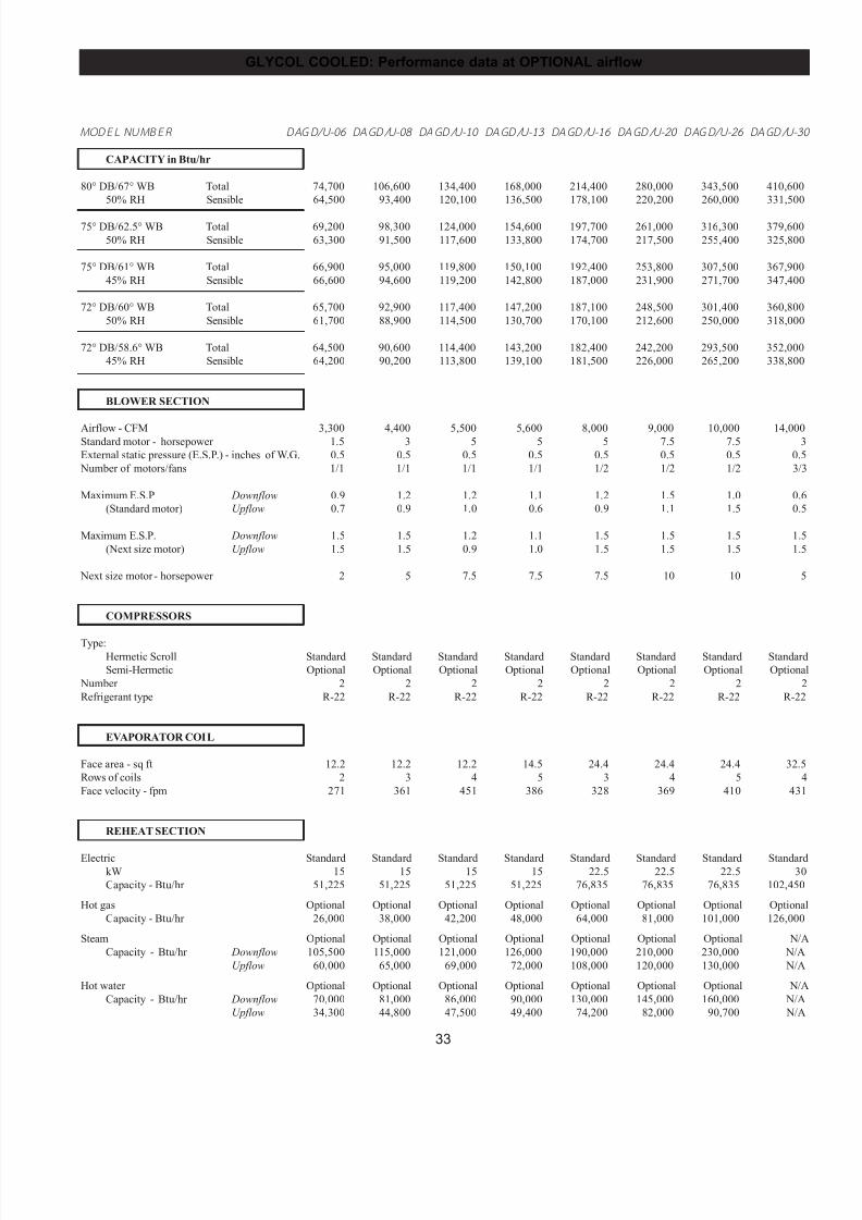
7/24/2019 DATA AIRE
http://slidepdf.com/reader/full/data-aire 33/76
33
M ODEL NUM BER DAGD/U-06 DAGD/U-08 DAGD/U-10 DAGD/U-13 DAGD/U-16 DAGD/U-20 DAGD/U-26 DAGD/U-3
CAPACITY in Btu/hr
80° DB/67° WB Total 74,700 106,600 134,400 168,000 214,400 280,000 343,500 410,600
50% RH Sensible 64,500 93,400 120,100 136,500 178,100 220,200 260,000 331,500
75° DB/62.5° WB Total 69,200 98,300 124,000 154,600 197,700 261,000 316,300 379,600
50% RH Sensible 63,300 91,500 117,600 133,800 174,700 217,500 255,400 325,800
75° DB/61° WB Total 66,900 95,000 119,800 150,100 192,400 253,800 307,500 367,900
45% RH Sensible 66,600 94,600 119,200 142,800 187,000 231,900 271,700 347,400
72° DB/60° WB Total 65,700 92,900 117,400 147,200 187,100 248,500 301,400 360,800
50% RH Sensible 61,700 88,900 114,500 130,700 170,100 212,600 250,000 318,000
72° DB/58.6° WB Total 64,500 90,600 114,400 143,200 182,400 242,200 293,500 352,000
45% RH Sensible 64,200 90,200 113,800 139,100 181,500 226,000 265,200 338,800
BLOWER SECTION
Airflow - CFM 3,300 4,400 5,500 5,600 8,000 9,000 10,000 14,000Standard motor - horsepower 1.5 3 5 5 5 7.5 7.5 3
External static pressure (E.S.P.) - inches of W.G. 0.5 0.5 0.5 0.5 0.5 0.5 0.5 0.5
Number of motors/fans 1/1 1/1 1/1 1/1 1/2 1/2 1/2 3/3
Maximum E.S.P Downflow 0.9 1.2 1.2 1.1 1.2 1.5 1.0 0.6
(Standard motor) Upflow 0.7 0.9 1.0 0.6 0.9 1.1 1.5 0.5
Maximum E.S.P. Downflow 1.5 1.5 1.2 1.1 1.5 1.5 1.5 1.5
(Next size motor) Upflow 1.5 1.5 0.9 1.0 1.5 1.5 1.5 1.5
Next size motor - horsepower 2 5 7.5 7.5 7.5 10 10 5
COMPRESSORS
Type:Hermetic Scroll Standard Standard Standard Standard Standard Standard Standard Standard
Semi-Hermetic Optional Optional Optional Optional Optional Optional Optional Optional
Number 2 2 2 2 2 2 2 2
Refrigerant type R-22 R-22 R-22 R-22 R-22 R-22 R-22 R-22
EVAPORATOR COIL
Face area - sq ft 12.2 12.2 12.2 14.5 24.4 24.4 24.4 32.5
Rows of coils 2 3 4 5 3 4 5 4
Face velocity - fpm 271 361 451 386 328 369 410 431
REHEAT SECTION
Electric Standard Standard Standard Standard Standard Standard Standard StandardkW 15 15 15 15 22.5 22.5 22.5 30
Capacity - Btu/hr 51,225 51,225 51,225 51,225 76,835 76,835 76,835 102,450
Hot gas Optional Optional Optional Optional Optional Optional Optional Optional
Capacity - Btu/hr 26,000 38,000 42,200 48,000 64,000 81,000 101,000 126,000
Steam Optional Optional Optional Optional Optional Optional Optional N/A
Capacity - Btu/hr Downflow 105,500 115,000 121,000 126,000 190,000 210,000 230,000 N/A
Upflow 60,000 65,000 69,000 72,000 108,000 120,000 130,000 N/A
Hot water Optional Optional Optional Optional Optional Optional Optional N/A
Capacity - Btu/hr Downflow 70,000 81,000 86,000 90,000 130,000 145,000 160,000 N/A
Upflow 34,300 44,800 47,500 49,400 74,200 82,000 90,700 N/A
GLYCOL COOLED: Performance data at OPTIONAL airflow
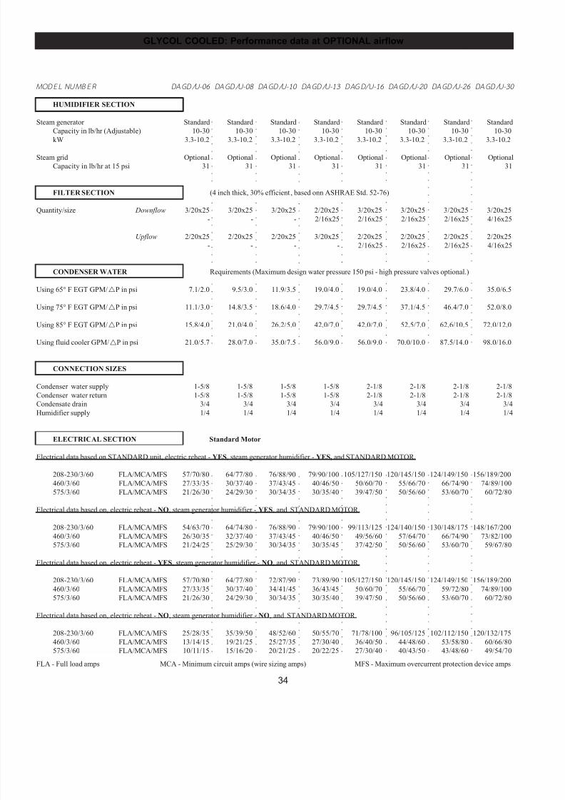
7/24/2019 DATA AIRE
http://slidepdf.com/reader/full/data-aire 34/76
34
GLYCOL COOLED: Performance data at OPTIONAL airflow
○
○
○
○
○
○
○
○
○
○
○
○
○
○
○
○
○
○
○
○
○
○
○
○
○
○
○
○
○
○
○
○
○
○
○
○
○
○
○
○
○
○
○
○
○
○
○
○
○
○
○
○
○
○
○
○
○
○
○
○
○
○
○
○
○
○
○
○
○
○
○
○
○
○
○
○
○
○
○
○
○
○
○
○
○
○
○
○
○
○
○
○
○
○
○
○
○
○
○
○
○
○
○
○
○
○
○
○
○
○
○
○
○
○
○
○
○
○
○
○
○
○
○
○
○
○
○
○
○
○
○
○
○
○
○
○
○
○
○
○
○
○
○
○
○
○
○
○
○
○
○
○
○
○
○
○
○
○
○
○
○
○
○
○
○
○
○
○
○
○
○
○
○
○
○
○
○
○
○
○
○
○
○
○
○
○
○
○
○
○
○
○
○
○
○
○
○
○
○
○
○
○
○
○
○
○
○
○
○
○
○
○
○
○
○
○
○
○
○
○
○
○
○
○
○
○
○
○
○
○
○
○
○
○
○
○
○
○
○
○
○
○
○
○
○
○
○
○
○
○
○
○
○
○
○
○
○
○
○
○
○
○
○
○
○
○
○
○
○
○
○
○
○
○
○
○
○
○
○
○
○
○
○
○
○
○
○
○
○
○
○
○
○
○
○
○
○
○
○
○
○
○
○
○
○
○
○
○
○
○
○
○
○
○
○
○
○
○
○
○
○
○
○
○
○
○
○
○
○
○
○
○
○
○
○
○
○
○
○
○
○
○
○
○
○
○
○
○
○
○
○
○
○
○
○
○
○
○
○
○
○
○
○
○
○
○
○
○
○
○
○
○
○
○
○
○
○
○
○
○
○
○
○
○
○
○
○
○
○
○
○
○
○
○
○
○
○
○
○
○
○
○
○
○
○
○
○
○
○
○
○
○
○
○
○
○
○
○
○
○
○
○
○
○
○
○
○
○
○
○
○
○
○
○
○
○
○
○
○
○
○
○
○
○
○
○
○
○
○
○
○
○
○
○
○
○
○
○
○
○
○
○
○
○
○
○
○
○
○
○
○
○
○
○
○
○
○
○
○
○
○
○
○
○
○
○
○
○
○
○
○
○
○
○
○
○
○
○
○
○
○
○
○
○
○
○
○
○
○
○
○
M ODEL NUM BER DAGD/U-06 DAGD/U-08 DAGD/U-10 DAGD/U-13 DAGD/U-16 DAGD/U-20 DAGD/U-26 DAGD/U-30
HUMIDIFIER SECTION
Steam generator Standard Standard Standard Standard Standard Standard Standard Standard
Capacity in lb/hr (Adjustable) 10-30 10-30 10-30 10-30 10-30 10-30 10-30 10-30
kW 3.3-10.2 3.3-10.2 3.3-10.2 3.3-10.2 3.3-10.2 3.3-10.2 3.3-10.2 3.3-10.2
Steam grid Optional Optional Optional Optional Optional Optional Optional Optional
Capacity in lb/hr at 15 psi 31 31 31 31 31 31 31 31
FILTER SECTION (4 inch thick, 30% efficient , based onn ASHRAE Std. 52-76)
Quantity/size Downflow 3/20x25 3/20x25 3/20x25 2/20x25 3/20x25 3/20x25 3/20x25 3/20x25
- - - 2/16x25 2/16x25 2/16x25 2/16x25 4/16x25
Upflow 2/20x25 2/20x25 2/20x25 3/20x25 2/20x25 2/20x25 2/20x25 2/20x25
- - - - 2/16x25 2/16x25 2/16x25 4/16x25
CONDENSER WATER Requirements (Maximum design water pressure 150 psi - high pressure valves optional.)
Using 65° F EGT GPM/!P in psi 7.1/2.0 9.5/3.0 11.9/3.5 19.0/4.0 19.0/4.0 23.8/4.0 29.7/6.0 35.0/6.5
Using 75° F EGT GPM/!P in psi 11.1/3.0 14.8/3.5 18.6/4.0 29.7/4.5 29.7/4.5 37.1/4.5 46.4/7.0 52.0/8.0
Using 85° F EGT GPM/!P in psi 15.8/4.0 21.0/4.0 26.2/5.0 42.0/7.0 42.0/7.0 52.5/7.0 62.6/10.5 72.0/12.0
Using fluid cooler GPM/!P in psi 21.0/5.7 28.0/7.0 35.0/7.5 56.0/9.0 56.0/9.0 70.0/10.0 87.5/14.0 98.0/16.0
CONNECTION SIZES
Condenser water supply 1-5/8 1-5/8 1-5/8 1-5/8 2-1/8 2-1/8 2-1/8 2-1/8
Condenser water return 1-5/8 1-5/8 1-5/8 1-5/8 2-1/8 2-1/8 2-1/8 2-1/8
Condensate drain 3/4 3/4 3/4 3/4 3/4 3/4 3/4 3/4
Humidifier supply 1/4 1/4 1/4 1/4 1/4 1/4 1/4 1/4
ELECTRICAL SECTION Standard Motor
Electrical data based on STANDARD unit, electric reheat - YES, steam generator humidifier - YES, and STANDARD MOTOR.
208-230/3/60 FLA/MCA/MFS 57/70/80 64/77/80 76/88/90 79/90/100 105/127/150 120/145/150 124/149/150 156/189/200
460/3/60 FLA/MCA/MFS 27/33/35 30/37/40 37/43/45 40/46/50 50/60/70 55/66/70 66/74/90 74/89/100
575/3/60 FLA/MCA/MFS 21/26/30 24/29/30 30/34/35 30/35/40 39/47/50 50/56/60 53/60/70 60/72/80
Electrical data based on, electric reheat - NO, steam generator humidifier - YES, and STANDARD MOTOR.
208-230/3/60 FLA/MCA/MFS 54/63/70 64/74/80 76/88/90 79/90/100 99/113/125 124/140/150 130/148/175 148/167/200
460/3/60 FLA/MCA/MFS 26/30/35 32/37/40 37/43/45 40/46/50 49/56/60 57/64/70 66/74/90 73/82/100
575/3/60 FLA/MCA/MFS 21/24/25 25/29/30 30/34/35 30/35/45 37/42/50 50/56/60 53/60/70 59/67/80
Electrical data based on, electric reheat - YES, steam generator humidifier - NO, and STANDARD MOTOR.
208-230/3/60 FLA/MCA/MFS 57/70/80 64/77/80 72/87/90 73/89/90 105/127/150 120/145/150 124/149/150 156/189/200
460/3/60 FLA/MCA/MFS 27/33/35 30/37/40 34/41/45 36/43/45 50/60/70 55/66/70 59/72/80 74/89/100
575/3/60 FLA/MCA/MFS 21/26/30 24/29/30 30/34/35 30/35/40 39/47/50 50/56/60 53/60/70 60/72/80
Electrical data based on, electric reheat - NO, steam generator humidifier - NO, and STANDARD MOTOR.
208-230/3/60 FLA/MCA/MFS 25/28/35 35/39/50 48/52/60 50/55/70 71/78/100 96/105/125 102/112/150 120/132/175
460/3/60 FLA/MCA/MFS 13/14/15 19/21/25 25/27/35 27/30/40 36/40/50 44/48/60 53/58/80 60/66/80
575/3/60 FLA/MCA/MFS 10/11/15 15/16/20 20/21/25 20/22/25 27/30/40 40/43/50 43/48/60 49/54/70
FLA - Full load amps MCA - Minimum circuit amps (wire sizing amps) MFS - Maximum overcurrent protection device amps
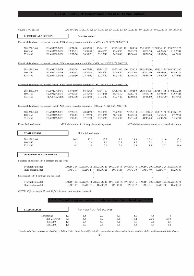
7/24/2019 DATA AIRE
http://slidepdf.com/reader/full/data-aire 35/76
35
GLYCOL COOLED: Performance data at OPTIONAL airflow
○
○
○
○
○
○
○
○
○
○
○
○
○
○
○
○
○
○
○
○
○
○
○
○
○
○
○
○
○
○
○
○
○
○
○
○
○
○
○
○
○
○
○
○
○
○
○
○
○
○
○
○
○
○
○
○
○
○
○
○
○
○
○
○
○
○
○
○
○
○
○
○
○
○
○
○
○
○
○
○
○
○
○
○
○
○
○
○
○
○
○
○
○
○
○
○
○
○
○
○
○
○
○
○
○
○
○
○
○
○
○
○
○
○
○
○
○
○
○
○
○
○
○
○
○
○
○
○
○
○
○
○
○
○
○
○
○
○
○
○
○
○
○
○
○
○
○
○
○
○
○
○
○
○
○
○
○
○
○
○
○
○
○
○
○
○
○
○
○
○
○
○
○
○
○
○
○
○
○
○
○
○
○
○
○
○
○
○
○
○
○
○
○
○
○
○
○
○
○
○
○
○
○
○
○
○
○
○
○
○
○
○
○
○
○
○
○
○
○
○
○
○
○
○
○
○
○
○
○
○
○
○
○
○
○
○
○
○
○
○
○
○
○
○
○
○
○
○
○
○
○
○
○
○
○
○
○
○
○
○
○
○
○
○
○
○
○
○
○
○
○
○
○
○
○
○
○
○
○
○
○
○
○
○
○
○
○
○
○
○
○
○
○
○
○
○
○
○
○
○
○
○
○
○
○
○
○
○
○
○
○
○
○
○
○
○
○
○
○
○
○
○
○
○
○
○
○
○
○
○
○
○
○
○
○
○
○
○
○
○
○
○
○
○
○
○
○
○
○
○
○
○
○
○
○
○
○
○
○
○
○
○
○
○
○
○
○
○
○
○
○
○
○
○
○
○
○
○
○
○
○
○
○
○
○
M ODEL NUM BER DAGD/U-06 DAGD/U-08 DAGD/U-10 DAGD/U-13 DAGD/U-16 DAGD/U-20 DAGD/U-26 DAGD/U-3
ELECTRICAL SECTION Next size motor
Electrical data based on, electric reheat - YES, steam generator humidifier - YES, and NEXT SIZE MOTOR.
208-230/3/60 FLA/MCA/MFS 58/71/80 68/82/90 83/94/100 86/97/100 111/134/150 125/150/175 129/154/175 170/203/225460/3/60 FLA/MCA/MFS 27/33/35 33/39/40 40/46/50 43/49/50 52/63/70 58/69/70 69/78/90 81/97/110
575/3/60 FLA/MCA/MFS 22/27/30 26/31/35 33/37/40 34/38/40 42/50/60 51/58/70 55/62/70 66/78/90
Electrical data based on, electric reheat - NO, steam generator humidifier - YES, and NEXT SIZE MOTOR.
208-230/3/60 FLA/MCA/MFS 55/65/70 69/79/80 83/94/100 86/97/100 106/120/125 129/145/150 135/153/175 163/182/200
460/3/60 FLA/MCA/MFS 26/30/35 34/39/40 40/46/50 43/49/50 52/58/60 60/67/80 69/78/90 80/89/100
575/3/60 FLA/MCA/MFS 21/25/30 27/31/35 33/37/40 34/38/40 40/46/50 51/58/70 55/62/70 65/73/80
Electrical data based on, electric reheat - YES, steam generator humidifier - NO, and NEXT SIZE MOTOR.
208-230/3/60 FLA/MCA/MFS 58/71/80 68/82/90 79/94/100 80/95/100 111/134/150 125/150/175 129/154/175 170/203/225
460/3/60 FLA/MCA/MFS 27/33/35 33/39/40 37/44/45 39/46/50 52/63/70 58/69/70 63/75/80 81/97/110
575/3/60 FLA/MCA/MFS 22/27/30 26/31/35 31/36/40 31/37/40 42/50/60 48/58/60 50/60/70 66/78/90
Electrical data based on, electric reheat - NO, steam generator humidifier - NO, and NEXT SIZE MOTOR.
208-230/3/60 FLA/MCA/MFS 27/29/35 40/44/50 55/59/70 57/62/80 78/85/110 101/110/125 107/117/150 134/146/175
460/3/60 FLA/MCA/MFS 13/14/15 21/23/30 27/30/35 30/33/40 39/42/50 47/51/60 56/62/80 67/73/90
575/3/60 FLA/MCA/MFS 11/12/15 17/18/20 23/25/30 23/25/30 30/33/40 41/45/60 45/49/60 55/60/70
FLA - Full load amps MCA - Minimum circuit amps (wire sizing amps) MFS - Maximum overcurrent protection device amps
COMPRESSOR FLA - full load amps
208-230/3/60 10.3 13.5 17.3 18.6 28.8 37.8 41.0 47.4
460/3/60 5.1 7.4 9.0 10.3 14.7 17.2 21.8 23.7
575/3/60 4.2 5.8 7.1 7.4 10.8 15.5 17.3 19.6
OUTDOOR FLUID COOLER
Standard selection at 95° F ambient and sea level
Evaporative model DAGD/U-06 DAGD/U-08 DAGD/U-10 DAGD/U-13 DAGD/U-16 DAGD/U-20 DAGD/U-26 DAGD/U-30
Fluid cooler model DAFC-11 DAFC-17 DAFC-21 DAFC-28 DAFC-30 DAFC-40 DAFC-44 DAFC-50
Selection at 100° F ambient and sea level
Evaporative model DAGD/U-06 DAGD/U-08 DAGD/U-10 DAGD/U-13 DAGD/U-16 DAGD/U-20 DAGD/U-26 DAGD/U-30
Fluid cooler model DAFC-17 DAFC-21 DAFC-24 DAFC-30 DAFC-37 DAFC-44 DAFC-50 DAFC-61
(NOTE: Refer to pages 59 and 62 for electrical data on fluid coolers.)
* * * The following section has no reference to column headings * * *
EVAPORATOR Fan motor FLA - f ull l oad amps
Horsepower 1.0 1.5 2.0 3.0 5.0 7.5 10
208-230/3/60 3.6 4.8 6.0 8.4 13.2 20.0 25.0
460/3/60 1.8 2.8 3.0 4.2 6.6 9.4 12.5
575/3/60 1.4 2.0 2.5 3.3 5.3 8.6 10.0
* Units with Energy Saver or Auxiliary Chilled Water Coils have different filter quantities as those listed in this section. Refer to dimensional data sheets.
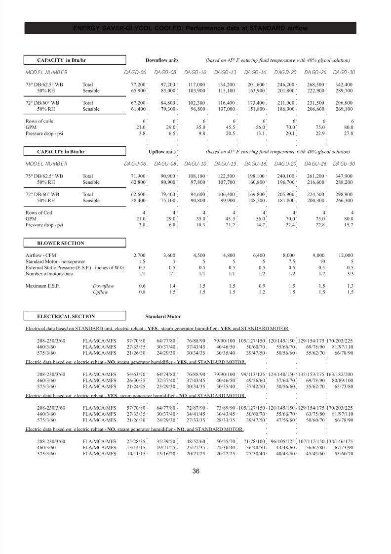
7/24/2019 DATA AIRE
http://slidepdf.com/reader/full/data-aire 36/76
36
ENERGY SAVER-GLYCOL COOLED: Performance data at STANDARD airflow
○
○
○
○
○
○
○
○
○
○
○
○
○
○
○
○
○
○
○
○
○
○
○
○
○
○
○
○
○
○
○
○
○
○
○
○
○
○
○
○
○
○
○
○
○
○
○
○
○
○
○
○
○
○
○
○
○
○
○
○
○
○
○
○
○
○
○
○
○
○
○
○
○
○
○
○
○
○
○
○
○
○
○
○
○
○
○
○
○
○
○
○
○
○
○
○
○
○
○
○
○
○
○
○
○
○
○
○
○
○
○
○
○
○
○
○
○
○
○
○
○
○
○
○
○
○
○
○
○
○
○
○
○
○
○
○
○
○
○
○
○
○
○
○
○
○
○
○
○
○
○
○
○
○
○
○
○
○
○
○
○
○
○
○
○
○
○
○
○
○
○
○
○
○
○
○
○
○
○
○
○
○
○
○
○
○
○
○
○
○
○
○
○
○
○
○
○
○
○
○
○
○
○
○
○
○
○
○
○
○
○
○
○
○
○
○
○
○
○
○
○
○
○
○
○
○
○
○
○
○
○
○
○
○
○
○
○
○
○
○
○
○
○
○
○
○
○
○
○
○
○
○
○
○
○
○
○
○
○
○
○
○
○
○
○
○
○
○
○
○
○
○
○
○
○
○
○
○
○
○
○
○
○
○
○
○
○
○
○
○
○
○
○
○
○
○
○
○
○
○
○
○
○
○
○
○
○
○
○
○
○
○
○
○
○
○
○
○
○
○
○
○
○
○
○
○
○
○
○
○
○
○
○
○
○
○
○
○
○
○
○
○
○
○
○
○
○
○
○
○
○
○
○
○
○
○
○
○
○
○
○
○
○
○
○
○
○
○
○
○
○
○
○
○
○
○
○
○
○
○
○
○
○
○
○
○
○
○
○
○
○
○
○
○
○
○
○
○
○
○
○
○
○
○
○
○
○
○
○
○
○
○
○
○
○
○
○
○
○
○
○
○
○
○
○
○
○
○
○
○
○
○
○
○
○
○
○
○
○
○
○
○
○
○
○
○
○
○
○
○
○
○
○
○
○
○
○
○
○
○
○
○
○
○
○
○
○
○
○
○
○
○
○
○
○
○
○
○
○
○
○
○
○
○
○
○
○
○
○
○
○
○
○
○
○
○
○
○
○
○
○
○
○
○
○
○
○
○
○
○
○
○
○
○
○
○
○
○
CAPACITY in Btu/hr Downflow units (based on 45° F entering fluid temperature with 40% glycol solution)
MODEL NUMBER DAGD-06 DAGD-08 DAGD-10 DAGD-13 DAGD-16 DAGD-20 DAGD-26 DAGD-30
75° DB/62.5° WB Total 77,200 97,200 117,000 134,200 201,600 246,200 268,500 342,400
50% RH Sensible 65,900 85,000 103,900 115,100 163,900 201,800 222,900 289,700
72° DB/60° WB Total 67,200 84,800 102,300 116,400 173,400 211,900 231,500 296,800
50% RH Sensible 61,400 79,300 96,800 107,000 151,800 186,900 206,600 269,100
Rows of coils 6 6 6 6 6 6 6 6
GPM 21.0 29.0 35.0 45.5 56.0 70.0 75.0 80.0
Pressure drop - psi 3.8 6.5 9.8 20.5 13.1 20.1 22.9 27.8
CAPACITY in Btu/hr Upflow units (based on 45° F entering fluid temperature with 40% glycol solution)
MODEL NUMBER DAGU-06 DAGU-08 DAGU-10 DAGU-13 DAGU-16 DAGU-20 DAGU-26 DAGU-30
75° DB/62.5° WB Total 71,900 90,900 108,100 122,500 198,100 240,100 261,200 347,900
50% RH Sensible 62,800 80,900 97,800 107,700 160,800 196,700 216,600 288,200
72° DB/60° WB Total 62,600 79,400 94,600 106,400 169,800 205,900 224,500 298,90050% RH Sensible 58,400 75,100 90,800 99,900 148,500 181,800 200,300 266,300
Rows of Coil 4 4 4 4 4 4 4 4
GPM 21.0 29.0 35.0 45.5 56.0 70.0 75.0 80.0
Pressure drop - psi 3.8 6.8 10.3 21.2 14.7 22.4 22.8 15.7
BLOWER SECTION
Airflow - CFM 2,700 3,600 4,500 4,800 6,400 8,000 9,000 12,000
Standard Motor - horsepower 1.5 3 5 5 5 7.5 10 5
External Static Pressure (E.S.P.) - inches of W.G. 0.5 0.5 0.5 0.5 0.5 0.5 0.5 0.5
Number of motors/fans 1/1 1/1 1/1 1/1 1/2 1/2 1/2 3/3
Maximum E.S.P. Downflow 0.6 1.4 1.5 1.5 0.9 1.5 1.5 1.3
Upflow 0.8 1.5 1.5 1.5 1.2 1.5 1.5 1.5
ELECTRICAL SECTION Standard Motor
Electrical data based on STANDARD unit, electric reheat - YES, steam generator humidifier - YES, and STANDARD MOTOR.
208-230/3/60 FLA/MCA/MFS 57/70/80 64/77/80 76/88/90 79/90/100 105/127/150 120/145/150 129/154/175 170/203/225
460/3/60 FLA/MCA/MFS 27/33/35 30/37/40 37/43/45 40/46/50 50/60/70 55/66/70 69/78/90 81/97/110
575/3/60 FLA/MCA/MFS 21/26/30 24/29/30 30/34/35 30/35/40 39/47/50 50/56/60 55/62/70 66/78/90
Electric data based on: electric reheat - NO, steam generator humidifier - YES, and STANDARD MOTOR.
208-230/3/60 FLA/MCA/MFS 54/63/70 64/74/80 76/88/90 79/90/100 99/113/125 124/140/150 135/153/175 163/182/200
460/3/60 FLA/MCA/MFS 26/30/35 32/37/40 37/43/45 40/46/50 49/56/60 57/64/70 69/78/90 80/89/100
575/3/60 FLA/MCA/MFS 21/24/25 25/29/30 30/34/35 30/35/40 37/42/50 50/56/60 55/62/70 65/73/80Electric data based on: electric reheat - YES, steam generator humidifier - NO, and STANDARD MOTOR.
208-230/3/60 FLA/MCA/MFS 57/70/80 64/77/80 72/87/90 73/89/90 105/127/150 120/145/150 129/154/175 170/203/225
460/3/60 FLA/MCA/MFS 27/33/35 30/37/40 34/41/45 36/43/45 50/60/70 55/66/70 63/75/80 81/97/110
575/3/60 FLA/MCA/MFS 21/26/30 24/29/30 27/33/35 28/33/35 39/47/50 47/56/60 50/60/70 66/78/90
Electric data based on: electric reheat - NO, steam generator humidifier - NO, and STANDARD MOTOR.
208-230/3/60 FLA/MCA/MFS 25/28/35 35/39/50 48/52/60 50/55/70 71/78/100 96/105/125 107/117/150 134/146/175
460/3/60 FLA/MCA/MFS 13/14/15 19/21/25 25/27/35 27/30/40 36/40/50 44/48/60 56/62/80 67/73/90
575/3/60 FLA/MCA/MFS 10/11/15 15/16/20 20/21/25 20/22/25 27/30/40 40/43/50 45/49/60 55/60/70
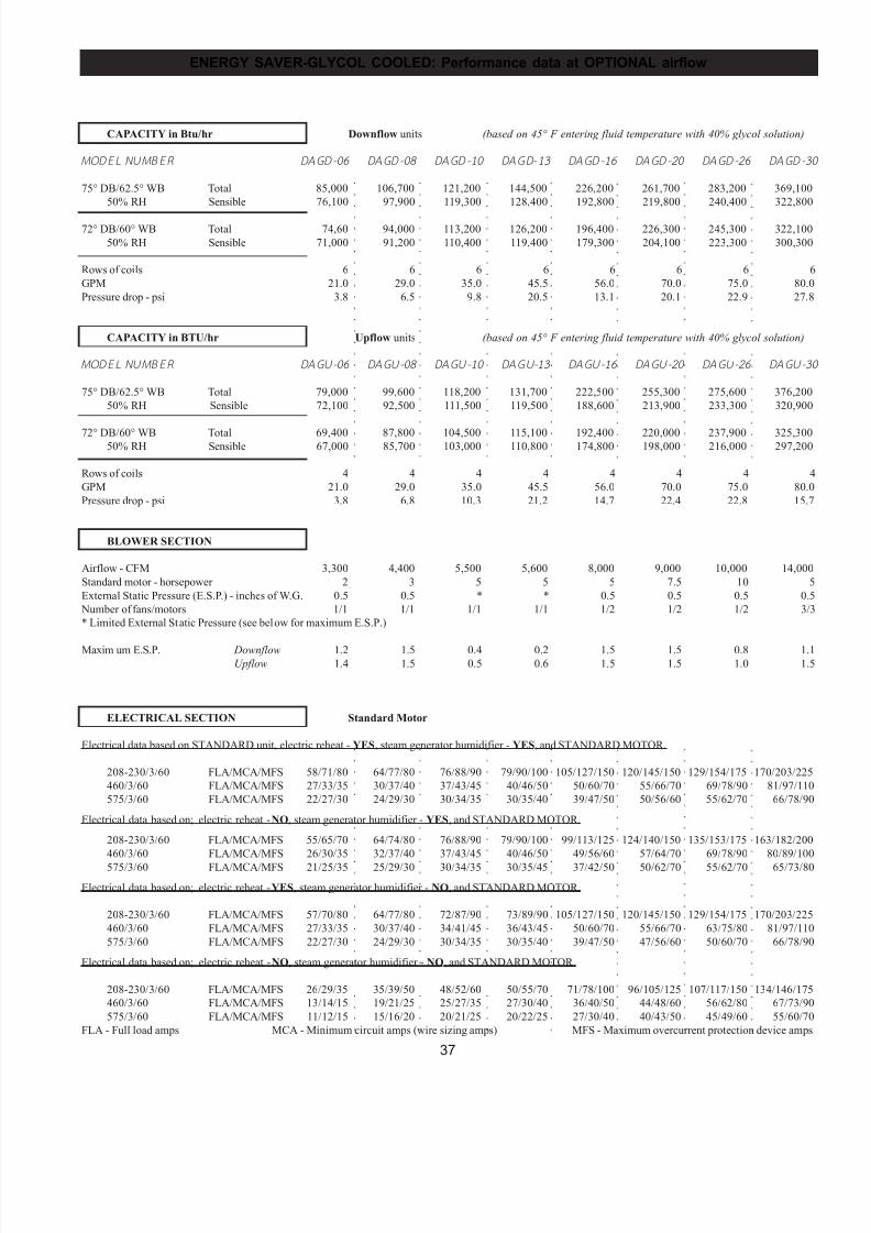
7/24/2019 DATA AIRE
http://slidepdf.com/reader/full/data-aire 37/76
37
ENERGY SAVER-GLYCOL COOLED: Performance data at OPTIONAL airflow
○
○
○
○
○
○
○
○
○
○
○
○
○
○
○
○
○
○
○
○
○
○
○
○
○
○
○
○
○
○
○
○
○
○
○
○
○
○
○
○
○
○
○
○
○
○
○
○
○
○
○
○
○
○
○
○
○
○
○
○
○
○
○
○
○
○
○
○
○
○
○
○
○
○
○
○
○
○
○
○
○
○
○
○
○
○
○
○
○
○
○
○
○
○
○
○
○
○
○
○
○
○
○
○
○
○
○
○
○
○
○
○
○
○
○
○
○
○
○
○
○
○
○
○
○
○
○
○
○
○
○
○
○
○
○
○
○
○
○
○
○
○
○
○
○
○
○
○
○
○
○
○
○
○
○
○
○
○
○
○
○
○
○
○
○
○
○
○
○
○
○
○
○
○
○
○
○
○
○
○
○
○
○
○
○
○
○
○
○
○
○
○
○
○
○
○
○
○
○
○
○
○
○
○
○
○
○
○
○
○
○
○
○
○
○
○
○
○
○
○
○
○
○
○
○
○
○
○
○
○
○
○
○
○
○
○
○
○
○
○
○
○
○
○
○
○
○
○
○
○
○
○
○
○
○
○
○
○
○
○
○
○
○
○
○
○
○
○
○
○
○
○
○
○
○
○
○
○
○
○
○
○
○
○
○
○
○
○
○
○
○
○
○
○
○
○
○
○
○
○
○
○
○
○
○
○
○
○
○
○
○
○
○
○
○
○
○
○
○
○
○
○
○
○
○
○
○
○
○
○
○
○
○
○
○
○
○
○
○
○
○
○
○
○
○
○
○
○
○
○
○
○
○
○
○
○
○
○
○
○
○
○
○
○
○
○
○
○
○
○
○
○
○
○
○
○
○
○
○
○
○
○
○
○
○
○
○
○
○
○
○
○
○
○
○
○
○
○
○
○
○
○
○
○
○
○
○
○
○
○
○
○
○
○
○
○
○
○
○
○
○
○
○
○
○
○
○
○
○
○
○
○
○
○
○
○
○
○
○
○
○
○
○
○
○
○
○
○
○
○
○
○
○
○
○
○
○
○
○
○
○
○
○
○
○
○
○
○
○
○
○
○
○
○
○
○
○
○
○
○
○
○
○
○
○
○
○
○
○
○
○
○
○
○
○
○
○
○
○
○
○
○
○
○
○
○
○
○
○
○
○
○
○
○
○
○
○
○
○
○
○
○
○
○
○
○
○
○
○
○
○
○
CAPACITY in Btu/hr Downflow units (based on 45° F entering fluid temperature with 40% glycol solution)
MODEL NUMBER DAGD-06 DAGD-08 DAGD-10 DAGD-13 DAGD-16 DAGD-20 DAGD-26 DAGD-3
75° DB/62.5° WB Total 85,000 106,700 121,200 144,500 226,200 261,700 283,200 369,100
50% RH Sensible 76,100 97,900 119,300 128,400 192,800 219,800 240,400 322,800
72° DB/60° WB Total 74,60 94,000 113,200 126,200 196,400 226,300 245,300 322,100
50% RH Sensible 71,000 91,200 110,400 119,400 179,300 204,100 223,300 300,300
Rows of coils 6 6 6 6 6 6 6 6
GPM 21.0 29.0 35.0 45.5 56.0 70.0 75.0 80.0
Pressure drop - psi 3.8 6.5 9.8 20.5 13.1 20.1 22.9 27.8
CAPACITY in BTU/hr Upflow units (based on 45° F entering fluid temperature with 40% glycol solution)
MODEL NUMBER DAGU-06 DAGU-08 DAGU-10 DAGU-13 DAGU-16 DAGU-20 DAGU-26 DAGU-3
75° DB/62.5° WB Total 79,000 99,600 118,200 131,700 222,500 255,300 275,600 376,200
50% RH Sensible 72,100 92,500 111,500 119,500 188,600 213,900 233,300 320,900
72° DB/60° WB Total 69,400 87,800 104,500 115,100 192,400 220,000 237,900 325,30050% RH Sensible 67,000 85,700 103,000 110,800 174,800 198,000 216,000 297,200
Rows of coils 4 4 4 4 4 4 4 4
GPM 21.0 29.0 35.0 45.5 56.0 70.0 75.0 80.0
Pressure drop - psi 3.8 6.8 10.3 21.2 14.7 22.4 22.8 15.7
BLOWER SECTION
Airflow - CFM 3,300 4,400 5,500 5,600 8,000 9,000 10,000 14,000
Standard motor - horsepower 2 3 5 5 5 7.5 10 5
External Static Pressure (E.S.P.) - inches of W.G. 0.5 0.5 * * 0.5 0.5 0.5 0.5
Number of fans/motors 1/1 1/1 1/1 1/1 1/2 1/2 1/2 3/3
* Limited External Static Pressure (see below for maximum E.S.P.)
Maxim um E.S.P. Downflow 1.2 1.5 0.4 0.2 1.5 1.5 0.8 1.1Upflow 1.4 1.5 0.5 0.6 1.5 1.5 1.0 1.5
ELECTRICAL SECTION Standard Motor
Electrical data based on STANDARD unit, electric reheat - YES, steam generator humidifier - YES, and STANDARD MOTOR.
208-230/3/60 FLA/MCA/MFS 58/71/80 64/77/80 76/88/90 79/90/100 105/127/150 120/145/150 129/154/175 170/203/225
460/3/60 FLA/MCA/MFS 27/33/35 30/37/40 37/43/45 40/46/50 50/60/70 55/66/70 69/78/90 81/97/110
575/3/60 FLA/MCA/MFS 22/27/30 24/29/30 30/34/35 30/35/40 39/47/50 50/56/60 55/62/70 66/78/90
Electrical data based on; electric reheat - NO, steam generator humidifier - YES, and STANDARD MOTOR.
208-230/3/60 FLA/MCA/MFS 55/65/70 64/74/80 76/88/90 79/90/100 99/113/125 124/140/150 135/153/175 163/182/200
460/3/60 FLA/MCA/MFS 26/30/35 32/37/40 37/43/45 40/46/50 49/56/60 57/64/70 69/78/90 80/89/100
575/3/60 FLA/MCA/MFS 21/25/35 25/29/30 30/34/35 30/35/45 37/42/50 50/62/70 55/62/70 65/73/80
Electrical data based on; electric reheat - YES, steam generator humidifier - NO, and STANDARD MOTOR.
208-230/3/60 FLA/MCA/MFS 57/70/80 64/77/80 72/87/90 73/89/90 105/127/150 120/145/150 129/154/175 170/203/225
460/3/60 FLA/MCA/MFS 27/33/35 30/37/40 34/41/45 36/43/45 50/60/70 55/66/70 63/75/80 81/97/110
575/3/60 FLA/MCA/MFS 22/27/30 24/29/30 30/34/35 30/35/40 39/47/50 47/56/60 50/60/70 66/78/90
Electrical data based on; electric reheat - NO, steam generator humidifier - NO, and STANDARD MOTOR.
208-230/3/60 FLA/MCA/MFS 26/29/35 35/39/50 48/52/60 50/55/70 71/78/100 96/105/125 107/117/150 134/146/175
460/3/60 FLA/MCA/MFS 13/14/15 19/21/25 25/27/35 27/30/40 36/40/50 44/48/60 56/62/80 67/73/90
575/3/60 FLA/MCA/MFS 11/12/15 15/16/20 20/21/25 20/22/25 27/30/40 40/43/50 45/49/60 55/60/70
FLA - Full load amps MCA - Minimum circuit amps (wire sizing amps) MFS - Maximum overcurrent protection device amps
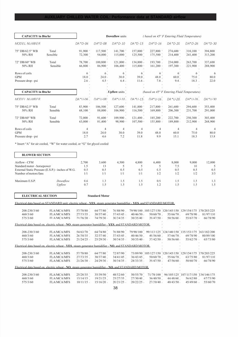
7/24/2019 DATA AIRE
http://slidepdf.com/reader/full/data-aire 38/76
38
AUXILIARY CHILLED WATER COIL: Performance data at STANDARD airflow
○
○
○
○
○
○
○
○
○
○
○
○
○
○
○
○
○
○
○
○
○
○
○
○
○
○
○
○
○
○
○
○
○
○
○
○
○
○
○
○
○
○
○
○
○
○
○
○
○
○
○
○
○
○
○
○
○
○
○
○
○
○
○
○
○
○
○
○
○
○
○
○
○
○
○
○
○
○
○
○
○
○
○
○
○
○
○
○
○
○
○
○
○
○
○
○
○
○
○
○
○
○
○
○
○
○
○
○
○
○
○
○
○
○
○
○
○
○
○
○
○
○
○
○
○
○
○
○
○
○
○
○
○
○
○
○
○
○
○
○
○
○
○
○
○
○
○
○
○
○
○
○
○
○
○
○
○
○
○
○
○
○
○
○
○
○
○
○
○
○
○
○
○
○
○
○
○
○
○
○
○
○
○
○
○
○
○
○
○
○
○
○
○
○
○
○
○
○
○
○
○
○
○
○
○
○
○
○
○
○
○
○
○
○
○
○
○
○
○
○
○
○
○
○
○
○
○
○
○
○
○
○
○
○
○
○
○
○
○
○
○
○
○
○
○
○
○
○
○
○
○
○
○
○
○
○
○
○
○
○
○
○
○
○
○
○
○
○
○
○
○
○
○
○
○
○
○
○
○
○
○
○
○
○
○
○
○
○
○
○
○
○
○
○
○
○
○
○
○
○
○
○
○
○
○
○
○
○
○
○
○
○
○
○
○
○
○
○
○
○
○
○
○
○
○
○
○
○
○
○
○
○
○
○
○
○
○
○
○
○
○
○
○
○
○
○
○
○
○
○
○
○
○
○
○
○
○
○
○
○
○
○
○
○
○
○
○
○
○
○
○
○
○
○
○
○
○
○
○
○
○
○
○
○
○
○
○
○
○
○
○
○
○
○
○
○
○
○
○
○
○
○
○
○
○
○
○
○
○
○
○
○
○
○
○
○
○
○
○
○
○
○
○
○
○
○
○
○
○
○
○
○
○
○
○
○
○
○
○
○
○
○
○
○
○
○
○
○
○
○
○
○
○
○
○
○
○
○
○
○
○
○
○
○
○
○
○
○
○
○
○
○
○
○
○
○
○
○
○
○
○
○
○
○
○
○
○
○
○
○
○
○
○
○
○
○
○
○
○
○
○
○
○
○
○
○
○
○
○
○
○
○
○
○
○
○
○
○
○
○
○
○
○
○
○
○
○
○
○
○
○
○
○
CAPACITY in Btu/hr Downflow units ( based on 45° F Entering Fluid Temperature)
MODEL NUMBER DA* D-06 DA*D-08 DA* D-10 DA*D-13 DA*D-16 DA* D-20 DA*D-26 DA* D-30
75° DB/62.5° WB Total 91,900 117,500 141,700 157,800 227,800 274,600 310,100 394,800
50% RH Sensible 72,300 94,000 115,000 125,500 175,500 214,400 241,400 313,200
72° DB/60° WB Total 78,700 100,800 121,800 134,800 193,700 234,000 263,700 337,600
50% RH Sensible 66,800 86,900 106,400 115,800 161,200 197,300 221,900 288,900
Rows of coils 6 6 6 6 6 6 6 6
GPM 18.0 24.0 30.0 39.0 48.0 60.0 75.0 80.0
Pressure drop - psi 2.6 4.5 6.4 11.6 7.8 9.4 18.3 22.0
CAPACITY in Btu/hr Upflow units (based on 45° F Entering Fluid Temperature)
MODEL NUMBER DA* U-06 DA*U-08 DA* U-10 DA*U-13 DA*U-16 DA* U-20 DA*U-26 DA* U-30
75° DB/62.5° WB Total 83,900 106,500 127,600 141,800 217,800 261,600 294,600 353,400
50% RH Sensible 68,100 88,000 106,900 116,500 169,800 206,300 231,700 291,000
72° DB/60° WB Total 72,000 91,600 109,900 121,400 185,200 222,700 250,300 303,40050% RH Sensible 63,000 81,400 98,900 107,500 155,800 189,800 212,900 268,900
Rows of coils 4 4 4 4 4 4 4 4
GPM 18.0 24.0 30.0 39.0 48.0 60.0 75.0 80.0
Pressure drop - psi 2.7 4.6 7.2 11.8 9.9 15.1 18.3 13.8
* Insert “A” for air cooled, “W” for water cooled, or “G” for glycol cooled
BLOWER SECTION
Airflow - CFM 2,700 3,600 4,500 4,800 6,400 8,000 9,000 12,000
Standard motor - horsepower 1.5 13 5 5 5 7.5 10 5
External Static Pressure (E.S.P.) - inches of W.G. 0.5 0.5 0.5 0.5 0.5 0.5 0.5 0.5
Number of motors/fans 1/1 1/1 1/1 1/1 1/2 1/2 1/2 3/3
Maximum E.S.P. Downflow 0.6 1.3 1.5 1.5 0.9 1.5 1.5 1.3
Upflow 0.7 1.5 1.5 1.5 1.2 1.5 1.5 1.5
ELECTRICAL SECTION Standard Motor
Electrical data based on STANDARD unit; electric reheat - YES, steam generator humidifier - YES, and STANDARD MOTOR.
208-230/3/60 FLA/MCA/MFS 57/70/80 64/77/80 76/88/90 79/90/100 105/127/150 120/145/150 129/154/175 170/203/225
460/3/60 FLA/MCA/MFS 27/33/35 30/37/40 37/43/45 40/46/50 50/60/70 55/66/70 69/78/90 81/97/110
575/3/60 FLA/MCA/MFS 21/26/30 24/29/30 30/34/35 30/35/40 39/47/50 50/56/60 55/62/70 66/78/90
Electrical data based on, electric reheat - NO, steam generator humidifier - YES, and STANDARD MOTOR.
208-230/3/60 FLA/MCA/MFS 54/63/70 64/74/80 76/88/90 79/90/100 99/113/125 124/140/150 135/153/175 163/182/200
460/3/60 FLA/MCA/MFS 26/30/35 32/37/40 37/43/45 40/46/50 49/56/60 57/66/70 69/78/90 80/89/100575/3/60 FLA/MCA/MFS 21/24/25 25/29/30 30/34/35 30/35/40 37/42/50 50/56/60 55/62/70 65/73/80
Electrical data based on, electric reheat - YES, steam generator humidifier - NO, and STANDARD MOTOR.
208-230/3/60 FLA/MCA/MFS 57/70/80 64/77/80 72/87/90 73/89/90 105/127/150 120/145/150 129/154/175 170/203/225
460/3/60 FLA/MCA/MFS 27/33/35 30/37/40 34/41/45 36/43/45 50/60/70 55/66/70 63/75/80 81/97/110
575/3/60 FLA/MCA/MFS 21/26/30 24/29/30 30/34/35 28/33/35 39/47/50 47/56/60 50/60/70 66/78/90
Electrical data based on, electric reheat - NO, steam generator humidifier - NO, and STANDARD MOTOR.
208-230/3/60 FLA/MCA/MFS 25/28/35 35/39/50 48/52/60 50/55/70 71/78/100 96/105/125 107/117/150 134/146/175
460/3/60 FLA/MCA/MFS 13/14/15 19/21/25 25/27/35 27/30/40 36/40/50 44/48/60 56/62/80 67/73/90
575/3/60 FLA/MCA/MFS 10/11/15 15/16/20 20/21/25 20/22/25 27/30/40 40/43/50 45/49/60 55/60/70
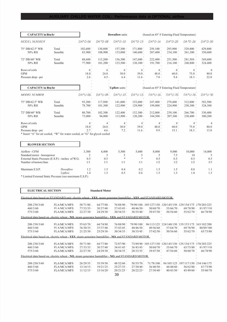
7/24/2019 DATA AIRE
http://slidepdf.com/reader/full/data-aire 39/76
39
AUXILIARY CHILLED WATER COIL: Performance data at OPTIONAL airflow
○
○
○
○
○
○
○
○
○
○
○
○
○
○
○
○
○
○
○
○
○
○
○
○
○
○
○
○
○
○
○
○
○
○
○
○
○
○
○
○
○
○
○
○
○
○
○
○
○
○
○
○
○
○
○
○
○
○
○
○
○
○
○
○
○
○
○
○
○
○
○
○
○
○
○
○
○
○
○
○
○
○
○
○
○
○
○
○
○
○
○
○
○
○
○
○
○
○
○
○
○
○
○
○
○
○
○
○
○
○
○
○
○
○
○
○
○
○
○
○
○
○
○
○
○
○
○
○
○
○
○
○
○
○
○
○
○
○
○
○
○
○
○
○
○
○
○
○
○
○
○
○
○
○
○
○
○
○
○
○
○
○
○
○
○
○
○
○
○
○
○
○
○
○
○
○
○
○
○
○
○
○
○
○
○
○
○
○
○
○
○
○
○
○
○
○
○
○
○
○
○
○
○
○
○
○
○
○
○
○
○
○
○
○
○
○
○
○
○
○
○
○
○
○
○
○
○
○
○
○
○
○
○
○
○
○
○
○
○
○
○
○
○
○
○
○
○
○
○
○
○
○
○
○
○
○
○
○
○
○
○
○
○
○
○
○
○
○
○
○
○
○
○
○
○
○
○
○
○
○
○
○
○
○
○
○
○
○
○
○
○
○
○
○
○
○
○
○
○
○
○
○
○
○
○
○
○
○
○
○
○
○
○
○
○
○
○
○
○
○
○
○
○
○
○
○
○
○
○
○
○
○
○
○
○
○
○
○
○
○
○
○
○
○
○
○
○
○
○
○
○
○
○
○
○
○
○
○
○
○
○
○
○
○
○
○
○
○
○
○
○
○
○
○
○
○
○
○
○
○
○
○
○
○
○
○
○
○
○
○
○
○
○
○
○
○
○
○
○
○
○
○
○
○
○
○
○
○
○
○
○
○
○
○
○
○
○
○
○
○
○
○
○
○
○
○
○
○
○
○
○
○
○
○
○
○
○
○
○
○
○
○
○
○
○
○
○
○
○
○
○
○
○
○
○
○
○
○
○
○
○
○
○
○
○
○
○
○
○
○
○
○
○
○
○
○
○
○
○
○
○
○
○
○
○
○
○
○
○
○
○
○
○
○
○
○
○
○
○
○
○
○
○
○
○
○
○
○
○
○
○
○
○
○
○
○
○
○
○
○
○
○
○
○
○
○
○
○
○
○
○
○
CAPACITY in Btu/hr Downflow units (based on 45° F Entering Fluid Temperature)
MODEL NUMBER DA*D-06 DA* D-08 DA*D-10 DA* D-13 DA*D-16 DA*D-20 DA*D-26 DA*D-30
75° DB/62.5° WB Total 102,600 130,800 157,300 171,800 259,100 293,900 329,800 429,800
50% RH Sensible 83,900 108,900 133,000 140,600 207,400 234,100 261,300 350,600
72° DB/60° WB Total 88,600 113,200 136,300 147,600 222,400 251,500 281,500 369,600
50% RH Sensible 77,900 101,200 123,500 130,100 191,700 216,100 240,800 324,400
Rows of coils 6 6 6 6 6 6 6 6
GPM 18.0 24.0 30.0 39.0 48.0 60.0 75.0 80.0
Pressure drop - psi 2.6 4.5 6.4 11.6 7.8 9.4 18.3 22.0
CAPACITY in Btu/hr Upflow units (based on 45° F Entering Fluid Temperature)
MODEL NUMBER DA*U-06 DA* U-08 DA*U-10 DA* U-13 DA*U-16 DA*U-20 DA*U-26 DA*U-30
75° DB/62.5° WB Total 93,200 117,900 141,000 153,600 247,400 279,600 312,800 382,500
50% RH Sensible 78,700 101,300 122,900 129,900 199,800 224,900 250,300 324,300
72° DB/60° WB Total 80,700 102,300 122,400 132,300 212,000 239,100 266,700 330,40050% RH Sensible 73,000 94,000 113,900 120,200 184,500 207,300 230,400 300,200
Rows of coils 4 4 4 4 4 4 4 4
GPM 18.0 24.0 30.0 39.0 48.0 60.0 75.0 80.0
Pressure drop - psi 2.7 4.6 7.2 11.6 9.9 15.1 18.3 13.8
* Insert “A” for air cooled, “W” for water cooled, or “G” for glycol cooled
BLOWER SECTION
Airflow - CFM 3,300 4,400 5,500 5,600 8,000 9,000 10,000 14,000
Standard motor - horsepower 2 3 5 5 5 7.5 10 5
External Static Pressure (E.S.P.) - inches of W.G. 0.5 0.5 * * 0.5 0.5 0.5 0.5
Number of motors/fans 1/1 1/1 1/1 1/1 1/2 1/2 1/2 3/3
Maximum E.S.P. Downflow 1.2 1.5 0.4 0.2 1.5 1.5 0.8 1.1Upflow 1.4 1.5 0.5 0.6 1.5 1.5 1.0 1.5
* Limited External Static Pressure (see maximum E.S.P.)
ELECTRICAL SECTION Standard Motor
Electrical data based on STANDARD unit; electric reheat - YES, steam generator humidifier - YES, and STANDARD MOTOR.
208-230/3/60 FLA/MCA/MFS 58/71/80 64/77/80 76/88/90 79/90/100 105/127/150 120/145/150 129/154/175 170/203/225
460/3/60 FLA/MCA/MFS 27/33/35 30/37/40 37/43/45 40/46/50 50/60/70 55/66/70 69/78/90 81/97/110
575/3/60 FLA/MCA/MFS 22/27/30 24/29/30 30/34/35 30/35/40 39/47/50 50/56/60 55/62/70 66/78/90
Electrical data based on, electric reheat - NO, steam generator humidifier - YES, and STANDARD MOTOR.
208-230/3/60 FLA/MCA/MFS 55/65/70 64/74/80 76/88/90 79/90/100 96/113/125 124/140/150 135/153/175 163/182/200460/3/60 FLA/MCA/MFS 26/30/35 32/37/40 37/43/45 40/46/50 49/56/60 57/64/70 69/78/90 80/89/100
575/3/60 FLA/MCA/MFS 21/25/30 25/29/30 30/34/35 30/35/45 37/42/50 50/56/60 55/62/70 65/73/80
Electrical data based on, electric reheat - YES, steam generator humidifier - NO, and STANDARD MOTOR.
208-230/3/60 FLA/MCA/MFS 58/71/80 64/77/80 72/87/90 73/89/90 105/127/150 120/145/150 129/154/175 170/203/225
460/3/60 FLA/MCA/MFS 27/33/35 30/37/40 34/41/45 36/43/45 50/60/70 55/66/70 63/75/80 81/97/110
575/3/60 FLA/MCA/MFS 22/27/30 24/29/30 30/34/35 28/33/35 39/47/50 47/56/60 50/60/70 66/78/90
Electrical data based on, electric reheat - NO, steam generator humidifier - NO, and STANDARD MOTOR.
208-230/3/60 FLA/MCA/MFS 26/29/35 35/39/50 48/52/60 50/55/70 71/78/100 96/105/125 107/117/150 134/146/175
460/3/60 FLA/MCA/MFS 13/14/15 19/21/25 25/27/35 27/30/40 36/40/50 44/48/60 56/62/80 67/73/90
575/3/60 FLA/MCA/MFS 11/12/15 15/16/20 20/21/25 20/22/25 27/30/40 40/43/50 45/49/60 55/60/70
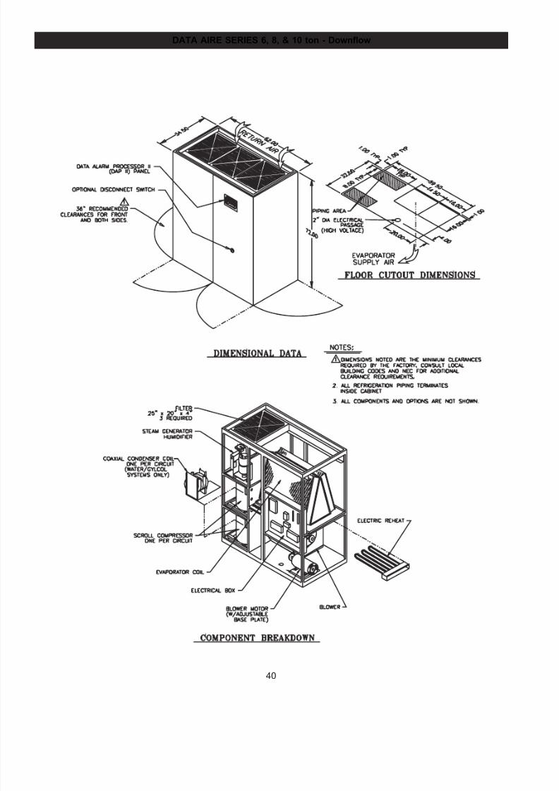
7/24/2019 DATA AIRE
http://slidepdf.com/reader/full/data-aire 40/76
40
DATA AIRE SERIES 6, 8, & 10 ton - Downflow

7/24/2019 DATA AIRE
http://slidepdf.com/reader/full/data-aire 41/76
41
DATA AIRE SERIES 6, 8, & 10 ton - Upflow
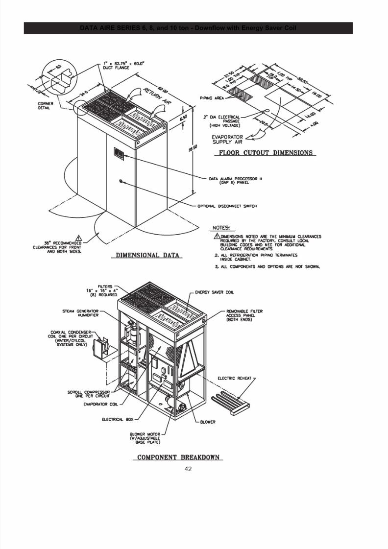
7/24/2019 DATA AIRE
http://slidepdf.com/reader/full/data-aire 42/76
42
DATA AIRE SERIES 6, 8, and 10 ton - Downflow with Energy Saver Coil
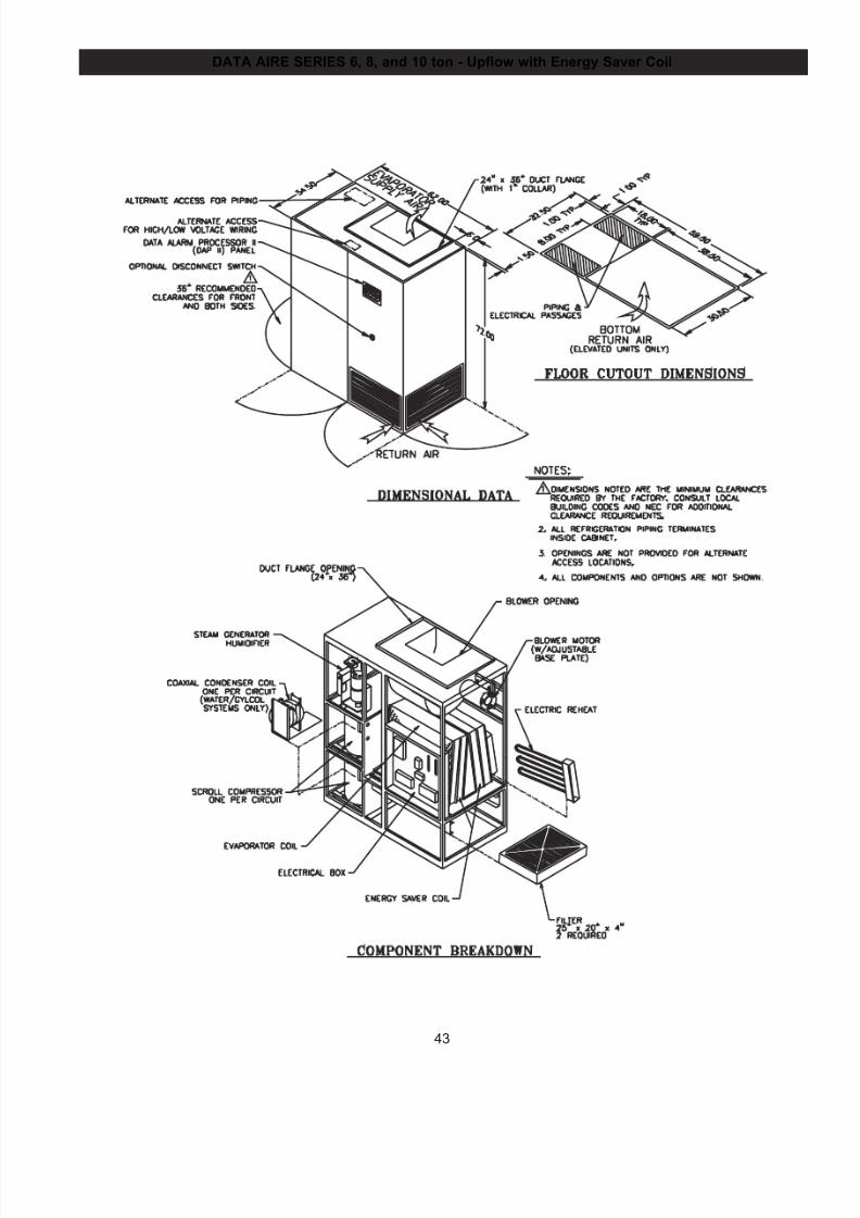
7/24/2019 DATA AIRE
http://slidepdf.com/reader/full/data-aire 43/76
43
DATA AIRE SERIES 6, 8, and 10 ton - Upflow with Energy Saver Coil
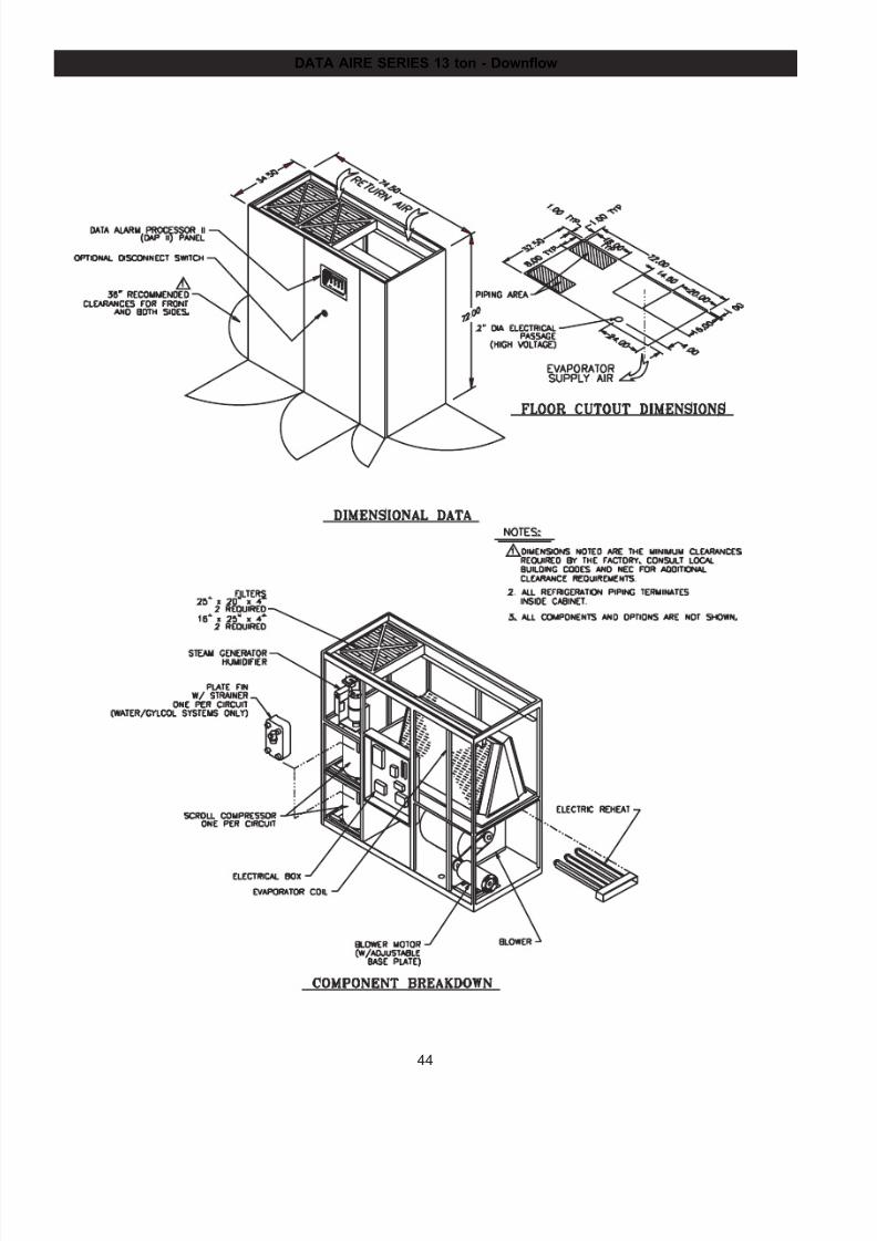
7/24/2019 DATA AIRE
http://slidepdf.com/reader/full/data-aire 44/76
44
DATA AIRE SERIES 13 ton - Downflow
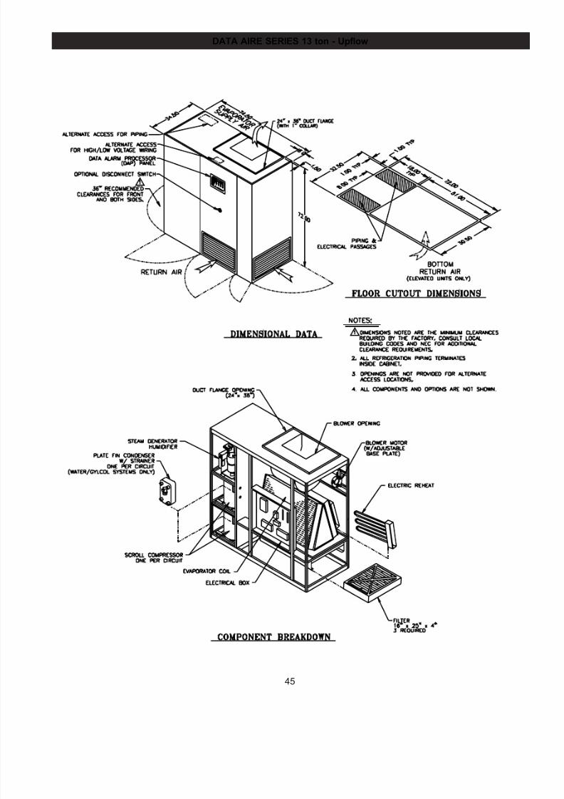
7/24/2019 DATA AIRE
http://slidepdf.com/reader/full/data-aire 45/76
45
DATA AIRE SERIES 13 ton - Upflow
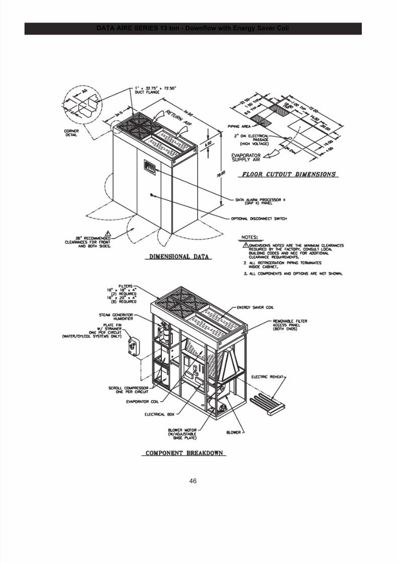
7/24/2019 DATA AIRE
http://slidepdf.com/reader/full/data-aire 46/76
46
DATA AIRE SERIES 13 ton - Downflow with Energy Saver Coil
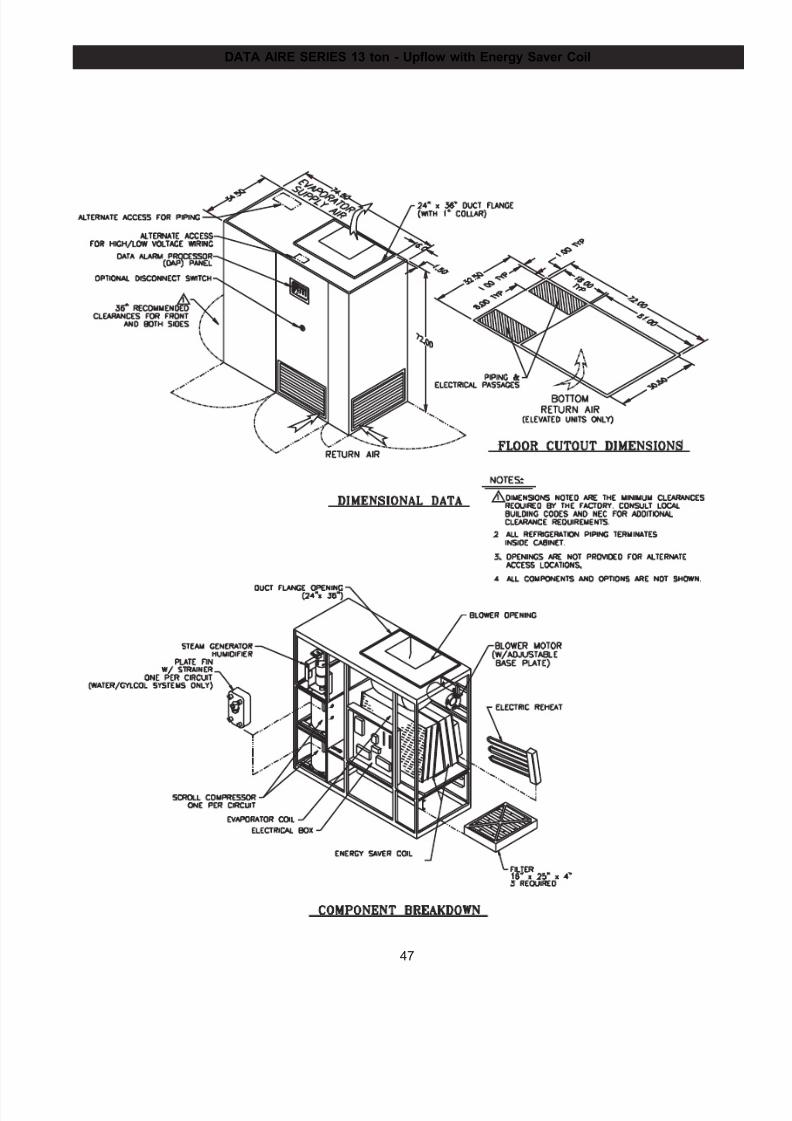
7/24/2019 DATA AIRE
http://slidepdf.com/reader/full/data-aire 47/76
47
DATA AIRE SERIES 13 ton - Upflow with Energy Saver Coil
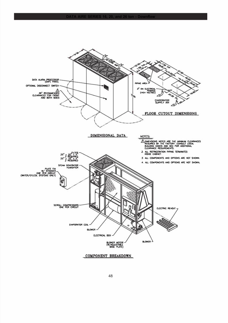
7/24/2019 DATA AIRE
http://slidepdf.com/reader/full/data-aire 48/76
48
DATA AIRE SERIES 16, 20, and 26 ton - Downflow
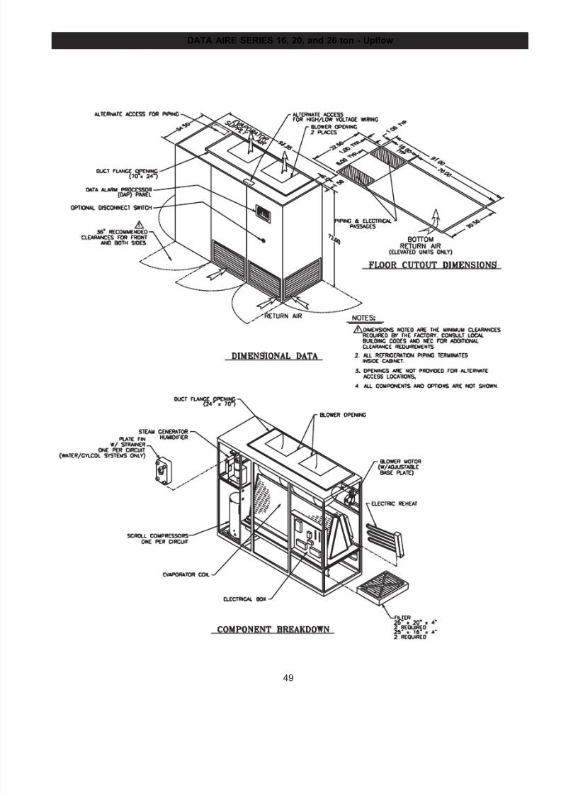
7/24/2019 DATA AIRE
http://slidepdf.com/reader/full/data-aire 49/76
49
DATA AIRE SERIES 16, 20, and 26 ton - Upflow
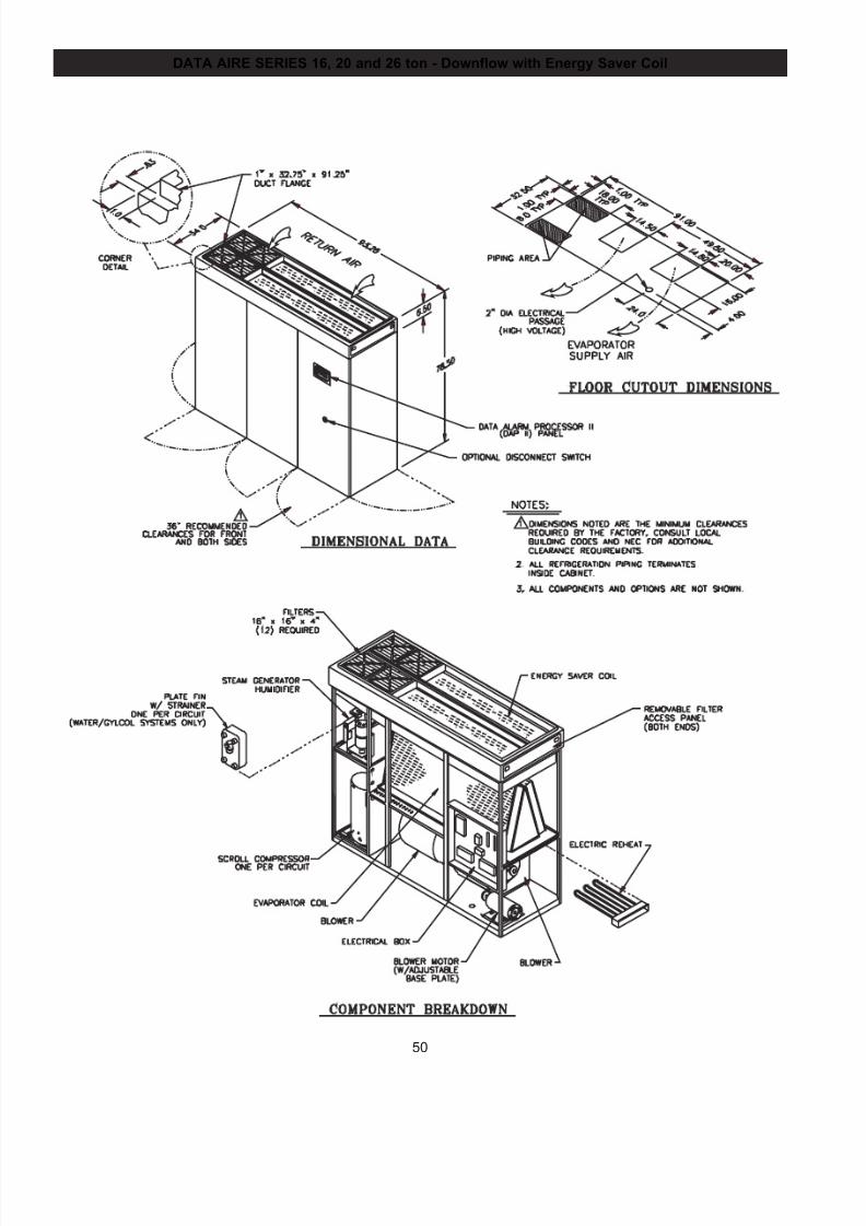
7/24/2019 DATA AIRE
http://slidepdf.com/reader/full/data-aire 50/76
50
DATA AIRE SERIES 16, 20 and 26 ton - Downflow with Energy Saver Coil
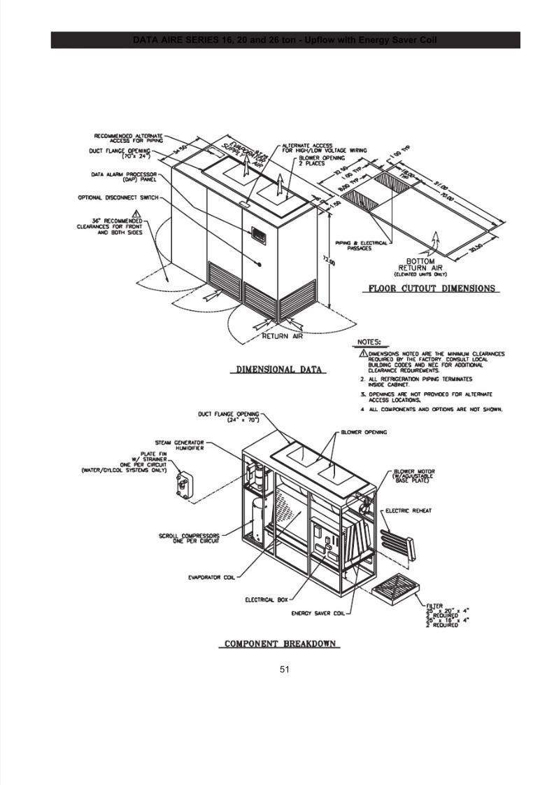
7/24/2019 DATA AIRE
http://slidepdf.com/reader/full/data-aire 51/76
51
DATA AIRE SERIES 16, 20 and 26 ton - Upflow with Energy Saver Coil
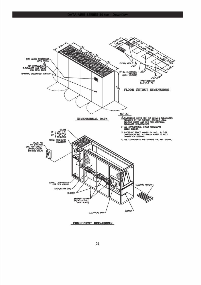
7/24/2019 DATA AIRE
http://slidepdf.com/reader/full/data-aire 52/76
52
DATA AIRE SERIES 30 ton - Downflow
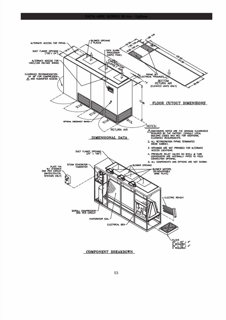
7/24/2019 DATA AIRE
http://slidepdf.com/reader/full/data-aire 53/76
53
DATA AIRE SERIES 30 ton - Upflow
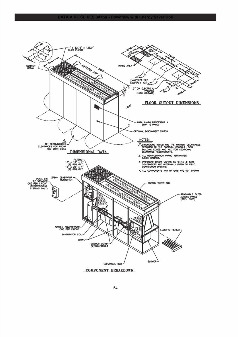
7/24/2019 DATA AIRE
http://slidepdf.com/reader/full/data-aire 54/76
54
DATA AIRE SERIES 30 ton - Downflow with Energy Saver Coil
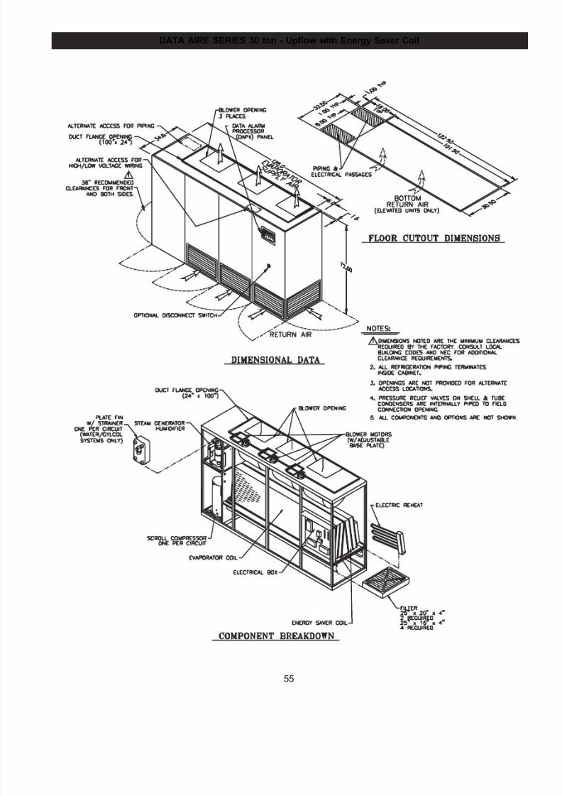
7/24/2019 DATA AIRE
http://slidepdf.com/reader/full/data-aire 55/76
55
DATA AIRE SERIES 30 ton - Upflow with Energy Saver Coil
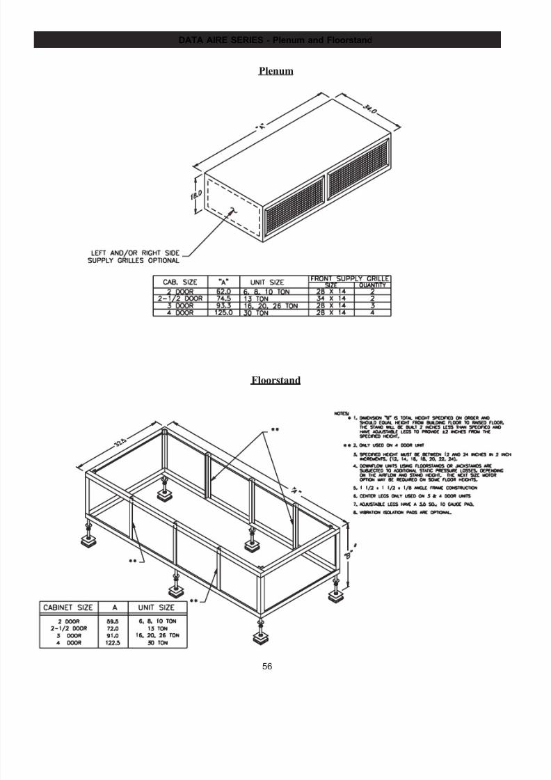
7/24/2019 DATA AIRE
http://slidepdf.com/reader/full/data-aire 56/76
56
DATA AIRE SERIES - Plenum and Floorstand
Plenum
Floorstand
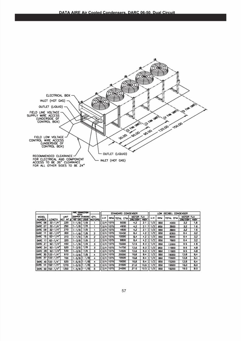
7/24/2019 DATA AIRE
http://slidepdf.com/reader/full/data-aire 57/76
57
DATA AIRE Air Cooled Condensers, DARC 06-50, Dual Circuit
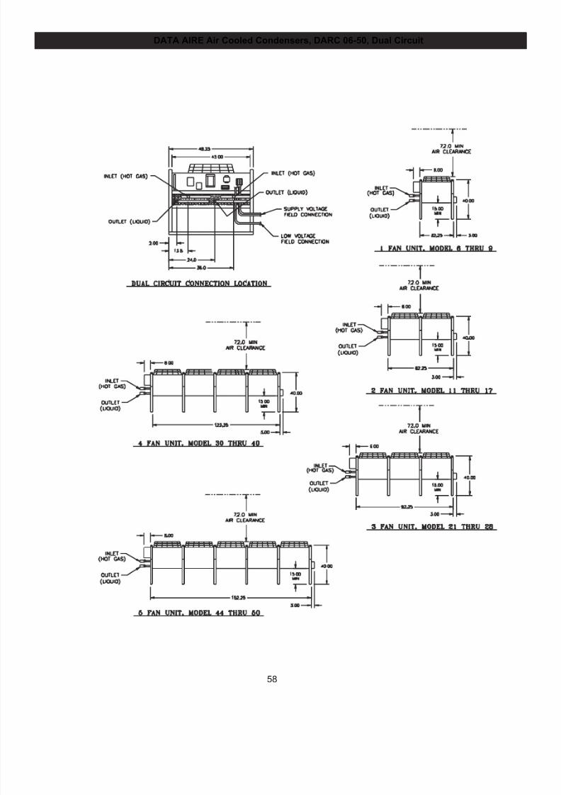
7/24/2019 DATA AIRE
http://slidepdf.com/reader/full/data-aire 58/76
58
DATA AIRE Air Cooled Condensers, DARC 06-50, Dual Circuit
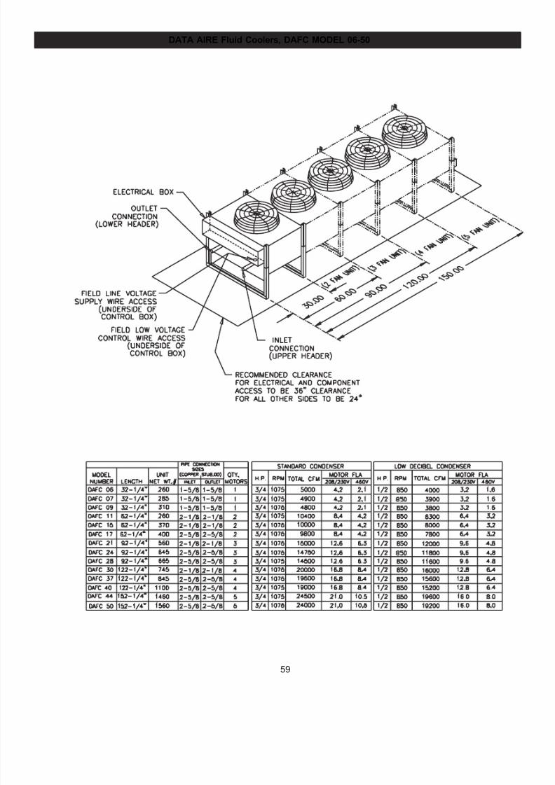
7/24/2019 DATA AIRE
http://slidepdf.com/reader/full/data-aire 59/76
59
DATA AIRE Fluid Coolers, DAFC MODEL 06-50
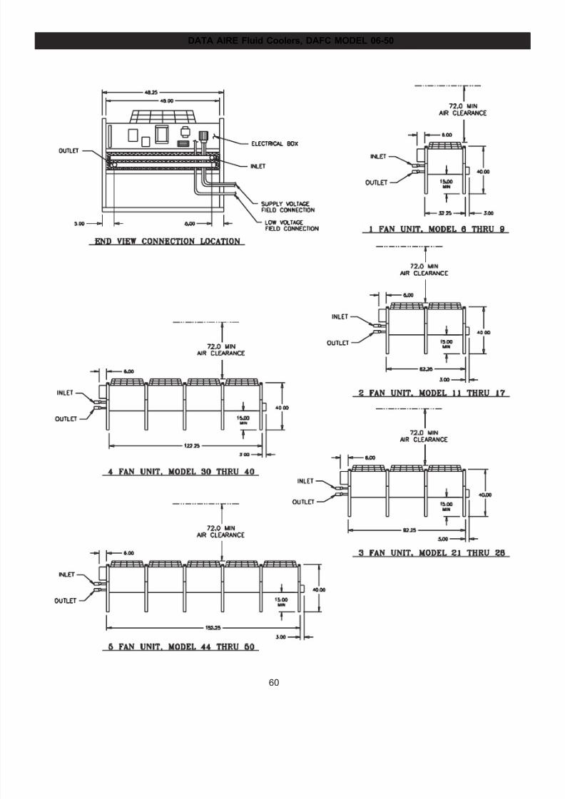
7/24/2019 DATA AIRE
http://slidepdf.com/reader/full/data-aire 60/76
60
DATA AIRE Fluid Coolers, DAFC MODEL 06-50
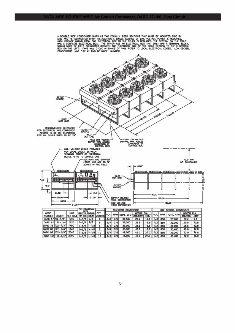
7/24/2019 DATA AIRE
http://slidepdf.com/reader/full/data-aire 61/76
61
DATA AIRE DOUBLE WIDE Air Cooled Condenser, DARC 57-100, Dual Circuit
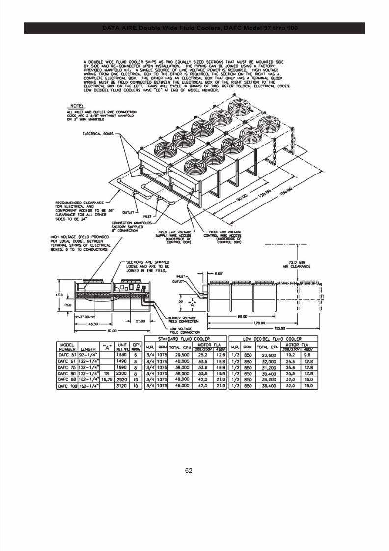
7/24/2019 DATA AIRE
http://slidepdf.com/reader/full/data-aire 62/76
62
DATA AIRE Double Wide Fluid Coolers, DAFC Model 57 thru 100
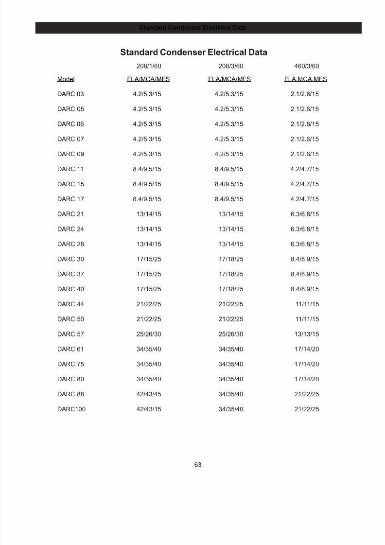
7/24/2019 DATA AIRE
http://slidepdf.com/reader/full/data-aire 63/76
63
Standard Condenser Electrical Data
208/1/60 208/3/60 460/3/60
Model FLA/MCA/MFS FLA/MCA/MFS FLA.MCA.MFS
DARC 03 4.2/5.3/15 4.2/5.3/15 2.1/2.6/15
DARC 05 4.2/5.3/15 4.2/5.3/15 2.1/2.6/15
DARC 06 4.2/5.3/15 4.2/5.3/15 2.1/2.6/15
DARC 07 4.2/5.3/15 4.2/5.3/15 2.1/2.6/15
DARC 09 4.2/5.3/15 4.2/5.3/15 2.1/2.6/15
DARC 11 8.4/9.5/15 8.4/9.5/15 4.2/4.7/15
DARC 15 8.4/9.5/15 8.4/9.5/15 4.2/4.7/15
DARC 17 8.4/9.5/15 8.4/9.5/15 4.2/4.7/15
DARC 21 13/14/15 13/14/15 6.3/6.8/15
DARC 24 13/14/15 13/14/15 6.3/6.8/15
DARC 28 13/14/15 13/14/15 6.3/6.8/15
DARC 30 17/15/25 17/18/25 8.4/8.9/15
DARC 37 17/15/25 17/18/25 8.4/8.9/15
DARC 40 17/15/25 17/18/25 8.4/8.9/15
DARC 44 21/22/25 21/22/25 11/11/15
DARC 50 21/22/25 21/22/25 11/11/15
DARC 57 25/26/30 25/26/30 13/13/15
DARC 61 34/35/40 34/35/40 17/14/20
DARC 75 34/35/40 34/35/40 17/14/20
DARC 80 34/35/40 34/35/40 17/14/20
DARC 88 42/43/45 34/35/40 21/22/25
DARC100 42/43/15 34/35/40 21/22/25
Standard Condenser Electrical Data
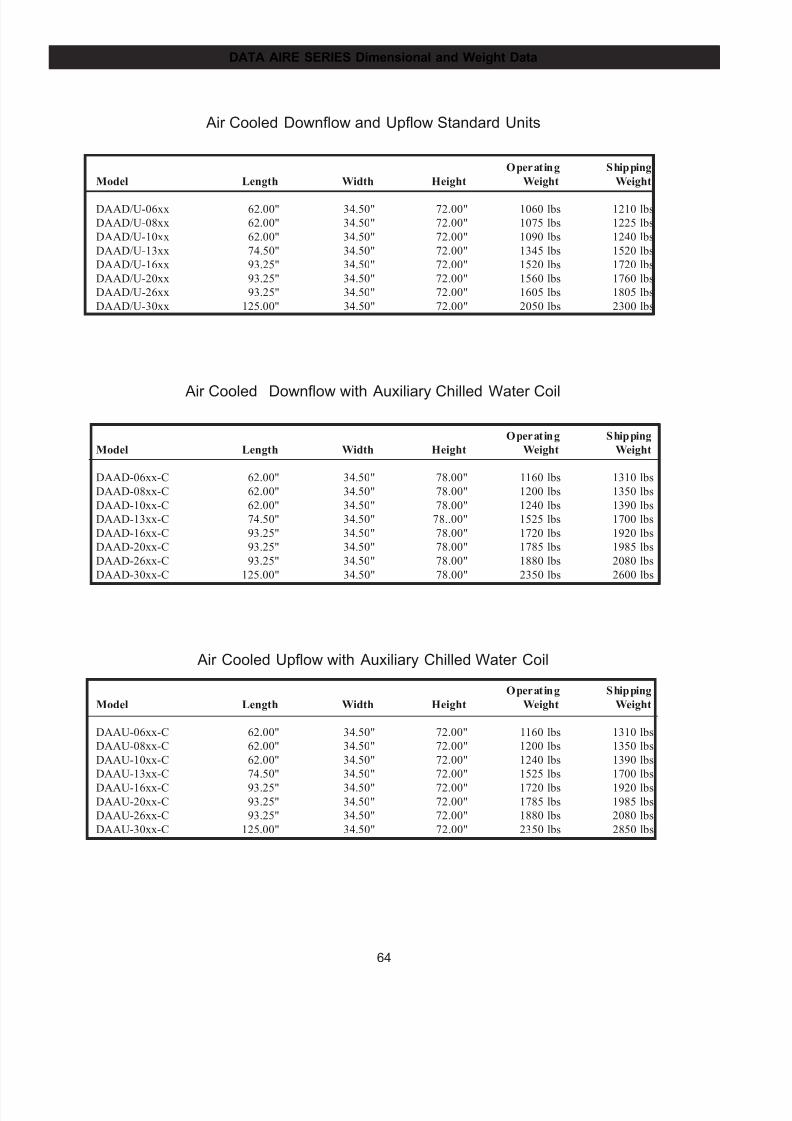
7/24/2019 DATA AIRE
http://slidepdf.com/reader/full/data-aire 64/76
64
DATA AIRE SERIES Dimensional and Weight Data
Air Cooled Downflow and Upflow Standard Units
Operating Shipping
Model Length Width Height Weight Weight
DAAD/U-06xx 62.00" 34.50" 72.00" 1060 lbs 1210 lbs
DAAD/U-08xx 62.00" 34.50" 72.00" 1075 lbs 1225 lbs
DAAD/U-10xx 62.00" 34.50" 72.00" 1090 lbs 1240 lbs
DAAD/U-13xx 74.50" 34.50" 72.00" 1345 lbs 1520 lbs
DAAD/U-16xx 93.25" 34.50" 72.00" 1520 lbs 1720 lbs
DAAD/U-20xx 93.25" 34.50" 72.00" 1560 lbs 1760 lbs
DAAD/U-26xx 93.25" 34.50" 72.00" 1605 lbs 1805 lbs
DAAD/U-30xx 125.00" 34.50" 72.00" 2050 lbs 2300 lbs
Air Cooled Downflow with Auxiliary Chilled Water Coil
Operating Shipping
Model Length Width Height Weight Weight
DAAD-06xx-C 62.00" 34.50" 78.00" 1160 lbs 1310 lbs
DAAD-08xx-C 62.00" 34.50" 78.00" 1200 lbs 1350 lbs
DAAD-10xx-C 62.00" 34.50" 78.00" 1240 lbs 1390 lbs
DAAD-13xx-C 74.50" 34.50" 78..00" 1525 lbs 1700 lbs
DAAD-16xx-C 93.25" 34.50" 78.00" 1720 lbs 1920 lbs
DAAD-20xx-C 93.25" 34.50" 78.00" 1785 lbs 1985 lbs
DAAD-26xx-C 93.25" 34.50" 78.00" 1880 lbs 2080 lbs
DAAD-30xx-C 125.00" 34.50" 78.00" 2350 lbs 2600 lbs
Air Cooled Upflow with Auxiliary Chilled Water Coil
Operating Shipping
Model Length Width Height Weight Weight
DAAU-06xx-C 62.00" 34.50" 72.00" 1160 lbs 1310 lbs
DAAU-08xx-C 62.00" 34.50" 72.00" 1200 lbs 1350 lbs
DAAU-10xx-C 62.00" 34.50" 72.00" 1240 lbs 1390 lbs
DAAU-13xx-C 74.50" 34.50" 72.00" 1525 lbs 1700 lbs
DAAU-16xx-C 93.25" 34.50" 72.00" 1720 lbs 1920 lbsDAAU-20xx-C 93.25" 34.50" 72.00" 1785 lbs 1985 lbs
DAAU-26xx-C 93.25" 34.50" 72.00" 1880 lbs 2080 lbs
DAAU-30xx-C 125.00" 34.50" 72.00" 2350 lbs 2850 lbs
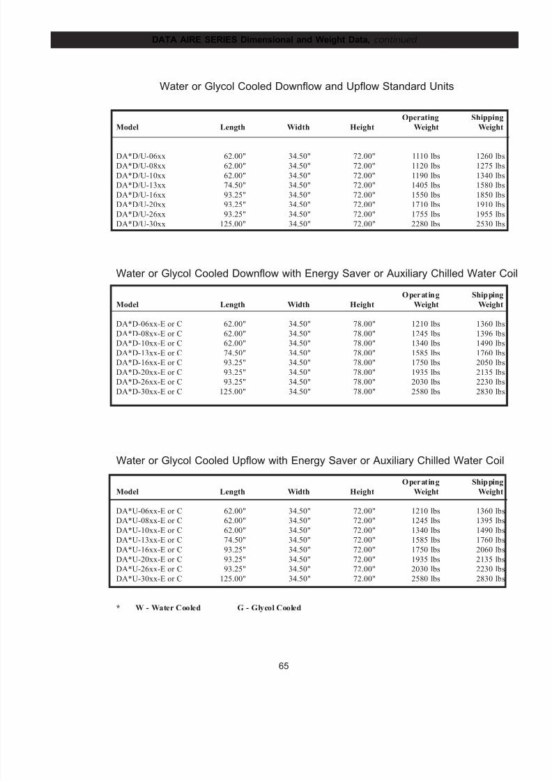
7/24/2019 DATA AIRE
http://slidepdf.com/reader/full/data-aire 65/76
65
DATA AIRE SERIES Dimensional and Weight Data, cont inued
Water or Glycol Cooled Downflow and Upflow Standard Units
Operating Shipping
Model Length Width Height Weight Weight
DA*D/U-06xx 62.00" 34.50" 72.00" 1110 lbs 1260 lbs
DA*D/U-08xx 62.00" 34.50" 72.00" 1120 lbs 1275 lbs
DA*D/U-10xx 62.00" 34.50" 72.00" 1190 lbs 1340 lbs
DA*D/U-13xx 74.50" 34.50" 72.00" 1405 lbs 1580 lbs
DA*D/U-16xx 93.25" 34.50" 72.00" 1550 lbs 1850 lbs
DA*D/U-20xx 93.25" 34.50" 72.00" 1710 lbs 1910 lbs
DA*D/U-26xx 93.25" 34.50" 72.00" 1755 lbs 1955 lbs
DA*D/U-30xx 125.00" 34.50" 72.00" 2280 lbs 2530 lbs
Water or Glycol Cooled Downflow with Energy Saver or Auxiliary Chilled Water Coi
Operating Shipping
Model Length Width Height Weight Weight
DA*D-06xx-E or C 62.00" 34.50" 78.00" 1210 lbs 1360 lbs
DA*D-08xx-E or C 62.00" 34.50" 78.00" 1245 lbs 1396 lbs
DA*D-10xx-E or C 62.00" 34.50" 78.00" 1340 lbs 1490 lbs
DA*D-13xx-E or C 74.50" 34.50" 78.00" 1585 lbs 1760 lbs
DA*D-16xx-E or C 93.25" 34.50" 78.00" 1750 lbs 2050 lbs
DA*D-20xx-E or C 93.25" 34.50" 78.00" 1935 lbs 2135 lbs
DA*D-26xx-E or C 93.25" 34.50" 78.00" 2030 lbs 2230 lbs
DA*D-30xx-E or C 125.00" 34.50" 78.00" 2580 lbs 2830 lbs
Water or Glycol Cooled Upflow with Energy Saver or Auxiliary Chilled Water Coil
Operating Shipping
Model Length Width Height Weight Weight
DA*U-06xx-E or C 62.00" 34.50" 72.00" 1210 lbs 1360 lbs
DA*U-08xx-E or C 62.00" 34.50" 72.00" 1245 lbs 1395 lbs
DA*U-10xx-E or C 62.00" 34.50" 72.00" 1340 lbs 1490 lbs
DA*U-13xx-E or C 74.50" 34.50" 72.00" 1585 lbs 1760 lbs
DA*U-16xx-E or C 93.25" 34.50" 72.00" 1750 lbs 2060 lbsDA*U-20xx-E or C 93.25" 34.50" 72.00" 1935 lbs 2135 lbs
DA*U-26xx-E or C 93.25" 34.50" 72.00" 2030 lbs 2230 lbs
DA*U-30xx-E or C 125.00" 34.50" 72.00" 2580 lbs 2830 lbs
* W - Water Cooled G - Glycol Cooled
7/24/2019 DATA AIRE
http://slidepdf.com/reader/full/data-aire 66/76
66
GENERAL
The environmental control units shall be provided with a high sensible cooling system, factory assembled,
piped, wired, and run tested prior to shipment and designed for the following air pattern:
___ Down Discharge ___ Top Discharge with Duct Connection
___ Top Discharge with Plenum
The system shall be designed for draw through air arrangement to insure even air distribution to the
entire face of the coil.
Units shall be ETL or UL listed.
CABINET and FRAME
The frame shall be constructed of 14 gauge welded tubular steel and coated with a heavy corrosion
inhibiting finish for long life. All internal fans shall be of high grade steel and shall be coated and sealed
for utmost protection against corrosion. The unit shall have complete front and side access by means of
high quality furniture grade steel doors with heavy duty hinges. The doors shall be lined with one inch
thick, 11/2 pound density fiberglass insulation coated with neoprene. Each door shall be provided with
sure close latches which shall be quickly removable for easy access and a polyurethane gasket to prevent
air leakage. The doors shall be painted to match or contrast with other equipment in the space. Bypass
air shall be provided around the cooling coil to preclude saturated air from being distributed to other
equipment in the controlled space. The cooling coil shall sit in a stainless steel drain pan.
The unit shall be painted _________________.
REFRIGERATION CIRCUI T
Air Cooled with Remote Outdoor Condenser - The refrigeration system shall be split type with an indoor evaporator section and remote outdoor condenser.
The indoor evaporator section shall include the cooling coil, compressors, humidifier, reheat, filters, and
controls. The cooling coil shall be in a cross circuited or interlaced "A" frame arrangement to allow
maximum coil surface in a small cabinet. The large faced coil area shall be constructed with 1/2" O.D.
copper tube with 12 fins per inch of corrugated aluminum for maximum heat transfer. Maximum face
velocity shall be less than 500 feet per minute. The expansion valves shall be of the adjustable
thermostatic type with external equalization. The compressors shall be of the hermetic scroll or semi-
hermetic type, with complete overload protection on all three power lines, internal thermostat for winding
protection, anti-slug device, crankcase heater, sight-glass, and low pressure override timer for positive
starting at low temperatures. The filter drier shall be of the flare fitting type for non-torch servicing. The
circuit shall contain high and low pressure safety switches. The high and low pressure safety switches
shall be installed with shraeder type fittings with valve core.
DATA AIRE SERIES 6 to 30 ton DX units - Guide Specifications
7/24/2019 DATA AIRE
http://slidepdf.com/reader/full/data-aire 67/76
67
Each system shall include a low profile, slow speed, direct drive propeller fan type air cooled condenser.
The air discharge shall be vertical to minimize the effects of wind blowing through the coil at low ambient
temperatures. The condenser shall be constructed of galvanized steel with a powder coated finish. The
condenser shall contain a 1/2" O.D. copper tube coil with corrugated aluminum fins for maximum heat
transfer. The condenser shall have fan speed control with transducers to modulate the speed of the first
condenser fan motor and provide positive start-up and operation at ambient temperatures to -20° F.Additional condenser fan motors are to be controlled by ambient thermostats. All controls including the
fan speed controller shall be factory mounted in the air cooled condenser in an integral factory wired and
tested control panel. The air cooled condenser shall be manufactured by the manufacturer of the indoor
unit.
Air Cooled with F loor M ounted I ndoor Condenser - The refrigeration system shall be split type with an
indoor evaporator section and floor mounted indoor condenser section.
The indoor evaporator section shall include the cooling coil, compressors, humidifier, reheat, filters, and
controls. The cooling coil shall be a cross circuited or interlaced "A" frame arrangement to allow
maximum coil surface in a small cabinet. The large faced coil area shall be constructed with 1/2" O.D.
copper tube with 12 fins per inch of corrugated aluminum for maximum heat transfer. Maximum face
velocity shall be less than 500 feet per minute. The expansion valves shall be of the adjustable type with
external equalization. The compressors shall be of the hermetic scroll or semi-hermetic type, with
complete overload protection on all three power lines, internal thermostat for winding protection, anti-
slug device, crankcase heater, sight-glass, and low pressure override timer for positive starting at low
temperatures. The filter drier shall be of the flare fitting type for non-torch servicing. The circuits shall
contain high and low pressure safety switches. The high and low pressure switches shall be installed with
shraeder type fittings with valve core.
Each system shall include a floor mounted, indoor air cooled condenser section. The condenser frame
shall be constructed of 14 gauge welded tubular steel and be coated with a heavy corrosion inhibiting
finish for long life. The unit shall have complete front and side access by means of high quality furniture
grade steel doors with heavy duty hinges. The doors shall be lined with one inch thick, 11/2 pound density
fiberglass coated with neoprene. Each door shall be provided with sure close latches which shall bequickly removable for easy access and a polyurethane gasket to prevent air leakage. The doors shall be
painted to match or contrast with other room equipment.
The blower section shall be belt driven centrifugal type, double width, double inlet and shall be statically
and dynamically balanced at the factory as a complete assembly to a maximum vibration level of two mills
in any plane. The blower wheel shall be a minimum of 15 inches in diameter. The blower wheel shall be
supported on a heavy steel shaft having self-aligning ball bearings with a minimum life span of 100,000
hours. The blower wheel shall be driven by a motor mounted on an adjustable slide base. The drive motor
shall be 1750 rpm. The drive package shall be belt driven with two belts and a variable pitch sheave,
sized for 200% of the fan motor horsepower.
The condenser coil shall be constructed of copper tubes and corrugated aluminum fins. The condenser
coil shall be equally circuited for each refrigeration compressor. A receiver shall be factory mounted withhead pressure control and solenoid valve for each circuit.
DATA AIRE SERIES 6 to 30 ton DX units - Guide Specifications, cont inued
7/24/2019 DATA AIRE
http://slidepdf.com/reader/full/data-aire 68/76
68
Ai r Cooled with Remote Outdoor Condensing Uni t - The refrigeration system shall be split type with an
indoor evaporator section and remote outdoor condensing unit.
The indoor evaporator section shall include the cooling coil, humidifier, reheat, filters, and controls. The
cooling coil shall be in a cross circuited or interlaced "A" frame arrangement to allow maximum coil
surface in a small cabinet. The large faced coil area shall be constructed with 1/2" O.D. copper tube with12 fins per inch of corrugated aluminum for maximum heat transfer. Maximum face velocity shall be less
than 500 feet per minute. The expansion valves shall be of the adjustable thermostatic type with external
equalization.
The outdoor condensing unit shall be constructed of galvanized steel with a powder coated finish and
contain hermetic scroll or semi-hermetic type compressors with complete overload protection on all three
power lines, internal thermostats for winding protection, anti-slug device, crankcase heater, sight-glass,
and low pressure override timer for positive starting at low temperatures. The filter drier shall be of the
flare fitting type for non-torch servicing. The circuits shall contain high and low pressure safety switches.
The high and low pressure safety switches shall be installed with shraeder type fittings with valve core.
The condensing unit shall include a low profile, slow speed, direct drive propeller fan air cooled
condenser section. The air discharge shall be vertical to minimize the effects of wind blowing through the
coil at low ambient temperatures. The condenser coil shall be constructed with copper tube and
aluminum fin. The condensing unit shall have fan speed control with transducers to modulate the speed
of the first condenser fan motor and provide positive start-up and operation at ambient temperatures to -
20° F. Additional condenser fan motors shall be controlled by ambient thermostats. All controls
including the fan speed control shall be factory mounted in an integral factory wired and tested control
panel. The condensing unit shall be manufactured by the manufacturer of the indoor unit.
Water/Glycol Cooled - The cooling coil shall be in a cross circuited or interlaced "A" frame arrangement to
allow maximum coil surface in a small cabinet. The large face area coil shall be constructed of 1/2" O.D.
copper tube with 12 fins per inch of corrugated aluminum for maximum heat transfer. Maximum face velocity
shall be less than 500 feet per minute. The expansion valves shall be of the adjustable thermostatic type with
external equalization. The compressors shall be of the hermetic scroll or semi-hermetic type with completeoverload protection on all three power lines, internal thermostats for winding protection, anti-slug device,
crankcase heater, sight-glass, condensers with sub-cooling and 2-way water regulating valve for head pressure
control. The filter drier shall be of the flare fitting type for non-torch servicing. The circuits shall contain high
and low pressure safety switches. The high and low pressure safety switches shall be installed with shraeder
type fittings with valve core.
Each system shall include a low profile, slow speed, direct drive propeller fan type air cooled fluid cooler.
Air discharge shall be vertical to prevent wind from blowing through the coil at low ambient
temperatures. The fluid cooler shall be constructed of galvanized steel with a powder coated finish and
contain a 1/2" O.D. copper tube coil with corrugated aluminum fins for maximum heat transfer. The fan
motors shall have cycling control provided on fluid coolers with multiple fan motors. The fluid cooler
shall include surge tank and fill valve, pump contactor, and fan cycling controls with integral factory
wired and tested control panel. The fluid cooler shall be manufactured by the manufacturer of the indoor unit.
DATA AIRE SERIES 6 to 30 ton DX units Guide Specifications, cont inued
7/24/2019 DATA AIRE
http://slidepdf.com/reader/full/data-aire 69/76
69
BLOWER SECTION
The blower shall be a belt driven centrifugal type, double width, double inlet and shall be statically and
dynamically balanced at the factory as a complete assembly to a maximum vibration level of two mils in
any plane. The blower wheel shall be a maximum of 15 inches in diameter.. The blower wheel shall be
supported on a heavy steel shaft having self-aligning ball bearings with a minimum life span of 100,000hours. The blower wheel shall be driven by a motor on an adjustable slide base. The drive motor shall be
1750 rpm. The drive package shall be belt driven with two (2) belts and variable pitch sheave sized for
200% of the fan motor horsepower. The blower shall be located to draw air over the coil to insure even air
distribution and maximum coil performance.
FI LTER CHAMBER
The filter chamber shall be an integral part of the system, designed within the frame and cabinet. The
filters shall be four inch (4") deep pleated design, rated not less than 30% efficient (based on ASHRAE
Std. 52-76).
ELECTRIC REHEAT
The reheat shall be of the finned enclosed, sheath type, fabricated of stainless steel core sheath with plated
fins to withstand moist conditions. The reheat shall be installed on the air discharge side of the cooling
coil and shall have three (3) stages. Each stage shall be ___ kW. The total kW shall be ___ to operate on
a supply of ____ volts.
HUMID IF IER
The unit shall be provided with steam generator type humidifier. The steam generating humidifier shall
be of the self-contained disposable cylinder type with electronic controls. The capacity shall be adjustablefrom 10 to 30 pounds per hour. Power consumption at 22 pounds per hour shall be 7.7 kW or less. The
humidifier shall discharge pure steam with no material dust carry-over and have a self-regulating
automatic flush cycle. Cylinders shall be disposable not requiring cleaning or maintenance. The
humidifier fill level, water conductivity and flush rate shall automatically adapt, both in frequency and
duration, to variations in the incoming water.
WATER SENSOR
Units shall be provided with one (1) water sensor. The solid state water sensor shall be mounted under the
unit to sense the presence of water. The sensor shall be connected to the microprocessor panel and
activate an audible alarm. The water detector shall become an integral part of the microprocessor panel
and shall display "WATER DETECTED IN UNDER FLOOR AREA" message when the sensor isactivated.
DATA AIRE SERIES 6 to 30 ton DX units Guide Specifications, cont inued
7/24/2019 DATA AIRE
http://slidepdf.com/reader/full/data-aire 70/76
70
CONTROL PANEL
The environmental control system shall be furnished with a microprocessor based Data Alarm Processor-I I
panel. The panel shall include unit switching functions and display normal functions, malfunctions, and
service diagnostics on a 2 row, 80 character, back-lit liquid crystal display (LCD) in a clear vernacular
format. The panel shall allow recall and display of the high and low temperature for the last 24 hours,high and low humidity for the last 24 hours, current percent of capacity and average percent of capacity
for the last hour of operation for cool 1, cool 2, reheat, humidification, and dehumidification, component
runtimes for fan motor, reheat, humidification, and dehumidification. Programming shall have
multilevel password access to prevent unauthorized access. Programming shall be accomplished entirely
from the front of the unit without the need to access, set, or program switches inside the unit (front door
of unit does not need to be opened). Programmable functions shall be entered on nonvolatile EEPROM to
insure program retention should power fail. The historical data base shall be maintained by battery
backup. Multiple messages shall be displayed by automatically scrolling from each message to the next.
Alarm conditions, in addition to being displayed, shall enunciate an audible alarm. A summary alarm
relay shall be available for remote alarms. Additional test or service terminal shall not be required for any
functions.
The control shall include temperature anticipation, moisture level humidity control and automatic flush
cycles.
An alarm condition shall continue to be displayed until the malfunction is corrected. Multiple alarms
shall be displayed sequentially in order of occurrence and only those alarms which have not been
acknowledged shall continue to sound an audible alarm. The Data Alarm Processor-II panel shall
perform an automatic self-test on system start-up. A user accessible diagnostic program shall aid in
system component trouble shooting by displaying on the unit LCD screen the name of the controlled item,
output relay number, terminal plug and pin number for each controlled item.
The following automatic control functions shall be included:
Selectable control type Start time delayTemperature anticipation Sequential load activation
Humidity anticipation Dehumidification lockout
Compressor short cycle Automatic reheat element rotation
Automatic or manual restart Energy saver (glycol operation)*
Auxiliary chilled water operation Hot water coil flush cycle*
Chilled water coil flush cycle* Energy Saver coil flush cycle*
The following conditions, data and normal functions shall be monitored and displayed:
Temperature setpoint Humidity setpoint
Current temperature Current humidity
Cooling 1, 2, 3, 4* Dehumidification
Reheat Current percentage of capacity utilizedHumidification Current discharge temperature*
The following switching and control functions shall be included:
System On/Off switch Menu selection button
Menu exit button Select button
Alarm silence button Program set button
Manual override for:
blower; cool 1, 2; heat 1; humidification
DATA AIRE SERIES 6 to 30 ton DX units Guide Specifications, cont inued
7/24/2019 DATA AIRE
http://slidepdf.com/reader/full/data-aire 71/76
71
The following historical data shall be available:
High temperature last 24 hours Low temperature last 24 hours
High humidity last 24 hours Low humidity last 24 hours
Alarm history (Last ten alarms) Equipment runtimes
Average percent of capacity
The following alarm functions shall be monitored and displayed when they occur in addition to
enunciating an audible alarm:
High temperature warning Low temperature warning
High humidity warning Low humidity warning
Compressor 1 high pressure Compressor 2 high pressure
Compressor 1 low pressure Compressor 2 low pressure
Under floor water detected No air flow
Dirty filter Humidifier failure
Manual override Compressor short cycle
Low voltage warning Power failure restart
Temperature sensor failure Humidity sensor failure
Maintenance required Person to contact on alarm*
Custom message* No water flow*
Firestat tripped Smoke detected*
Discharge air sensor failure* Fan motor overload*
Local alarm*
The following functions shall be programmable:
Temperature setpoint Humidity setpoint
(65-85° F, 18.3-29.4° C) (30-70% RH)
Temperature deadband Humidity deadband
(± 1-5° F/C) (1-15% RH)High temperature alarm limit High humidity alarm limit
Low temperature alarm limit Low humidity alarm limit
Mode and stage response rime Compressor lead/lag sequence
Reset equipment runtimes Audio alarm mode
Manual diagnostics Compressor short cycle alarm
Compressor supplements to Energy Saver* Define password
Humidifier autoflush timer Firestat temperature alarm limit
Scheduled maintenance Temperature scale
Control logic Calibrate temperature sensor
Calibrate humidity sensor Water valve mode
Low discharge temperature alarm limit* Message for optional alarm limit*
Delay for optional alarms Remote alarm 1, 2, 3 selection*
Person to contact on alarm Automatic self-testHumidity anticipation Dehumidification mode
Power problem or restart mode Calibrate discharge air sensor*
Reheat stages Humidifier
* Some of the programmable selections, displays, or alarms may require additional components or sensors.
DATA AIRE SERIES 6 to 30 ton DX units Guide Specifications, cont inued
7/24/2019 DATA AIRE
http://slidepdf.com/reader/full/data-aire 72/76
72
Data Ai re Remote Telecommun icati ons System 200 TM
Provide the Data A ir e Remote Telecommun icati ons System 200 (DART System 200) for comprehensive monitoring and
control of the environmental control units via a phone modem to a host PC station. The environmental control units shall be
interfaced with a communications module (DART-Board) with integral phone modem.
The DART System 200 shall allow complete remote control, monitoring, and retrieval of all historical data of the Data Aire
units through the unit mounted Data Alarm Processor-I I TM . Upon alarm at the unit, the DART-Board shall automatically
dial one or two pre-programmed numbers and transmit specific alarm information. All entry or configuration capabilities
available at the Data Al arm Processor-I I shall be accessible at the host station. The commands or requests for data from each
unit shall processed through the DART-Board. A single DART-Board shall allow up to 32 Data Aire units to be connected and
controlled. The DART System 200 shall be capable of monitoring and controlling up to 200 DART-Boards.
The following system features shall be provided:
Automaticscrolling of current status Automatic scrolling of sensor readings
Sensor database Sequential display of alarms
Password access Multiple audio alarm modes
Automatic status log prints Custom "Help" messages for alarms
The following programmable functions shall be provided:
Temperature setpoint Humidity setpoint
Temperature high limit Humidity high limit
Temperature low limit Humidity low limit
Temperature sensitivity (Deadband) Humidity sensitivity (Deadband)
On/Off/Standby operation Unit rotation
Unit identification number Zone number
Password
The following conditions shall be monitored:
Specific alarms from unit(s) All standard alarms from unit(s)
Programmed local alarms from unit(s) Current operating mode
Current temperature sensor readings Current humidity sensor readings
The following historical data shall be provided:
Alarm history for last 10 alarms in order Equipment runtimes for:
of occurrence and time since detected evaporator fan motors,
Current and average percent of capacity compressors,
for last hour reheat,
High and low temperature last 24 hours humidification,
High and low humidity last 24 hours dehumidification,Energy Saver Cooling*,
Chilled Water Cooling*.
* Some programmable selections, displays, and alarms may require optional components or sensors.
OPTIONS
7/24/2019 DATA AIRE
http://slidepdf.com/reader/full/data-aire 73/76
73
Energy Saver Coil - The environmental control units shall be provided with an Energy Saver Coil . The Energy Saver Coil
shall be an integral part of the unit and will be capable of providing the total cooling capacity. Whenever the incoming wa-
ter/glycol temperature is below the setpoint of the water changeover thermostat, Energy Saver cooling shall be available.
The Energy Saver shall operate in the following range: Return air setpoint plus deadband plus 2 degrees.
The Energy Saver shall operate providing there is a need for cooling. The valve shall open at setpoint plus deadband. The valve
shall modulate as long as the space is between setpoint plus deadband plus 2 degrees. If the temperature falls below the
deadband minus setpoint, the valve shall close and the space shall be considered satisfied. While still in Energy Saver with the
valve modulating, if the temperature goes beyond setpoint plus deadband plus 2 degrees, the Energy Saver valve shall close and
mechanical (DX) cooling shall begin.
The Energy Saver Coil shall include 3-way pressure control valves on the condenser circuits and 3-way valve on the economy
coil. Common piping for the energy coil and condensers shall be provided.
Energy Saver/Compressor Supplement - Units with Energy Saver shall be provided with compressor supplement if the En-
ergy Saver is not sufficient as a stand alone system. When the incoming water/glycol temperature is below the setpoint of the
water changeover thermostat, the Energy Saver shall be enabled (even if there is no call for cooling). Upon a call for cooling
(setpoint plus deadband), the valve shall open proportionally - 10% for each 0.1° above setpoint plus deadband. The com-
pressor shall come on at setpoint plus deadband plus 1.3° (the valve shall be 100% open at this point). The compressor shall
go off at setpoint plus 1.3° The valve shall close proportionally - 10% for each 0.1° below setpoint. An air discharge sensor
shall be factory mounted.
Auxi liar y Chill ed Water Coil - Units shall be provided with an Auxiliary Chilled Water Coil. The existing chilled water
loop shall be utilized with the Auxiliary Chilled water coil. Units shall operate using the chilled water for cooling. Upon a
loss of water flow or an increase in room temperature the system shall bring on compressor (DX) cooling. Separate piping
shall be provided for the chilled water coil and refrigeration connections.
Remote Temperatu re & Humidity Sensors - Units shall be provided with remote temperature and humidity sensors. Sensors
shall be provided in a plastic case for remote mounting. 25 feet of shielded cable shall be provided for field wiring.
Disconnect - The environmental control unit shall include a nonautomatic disconnect switch mounted in the high voltage
section of the electrical panel. The operating mechanism shall prevent access to the high voltage electrical components until
switched to the "OFF" position. The operating mechanism shall protrude through the decorative door.
Smoke Detector - The environmental control unit shall be provided with a smoke detector. The smoke detector shall be
mounted with the sensing element in the return air stream. When the smoke detector is activated, it shall immediately shut
down the unit.
Condensate Pump - Units shall be provided with condensate pumps. Pumps shall be factory mounted/wired or shipped loose
for field installation and shall include sump, motor, and automatic control. The pumps shall be rated for 130 GPH @ 20 foot
maximum head (40 GPH @ 20 feet with check valve).
Tandem Scrol l Compressors - Provide units with tandem hermetic scroll compressors with two step modulation for stagecontrol. Each circuit shall contain two scroll compressors. Modulation shall allow one or both compressors (per circuit) to
run depending upon the load of the system, resulting in part-load efficiency equal to full load efficiency.
OPTIONS, cont inued
7/24/2019 DATA AIRE
http://slidepdf.com/reader/full/data-aire 74/76
74
Semi-H ermetic Compressors - Units shall be provided with semi-hermetic compressors. Compressor shall have suction gas
cooled motor, thermal overloads, vibration isolators, oil sight-glass, reversible oil pump, suction and discharge ports, manual
reset high pressure switch, with a maximum operating speed of 1750 rpm. The compressors shall be installed with hot gas
mufflers, liquid line solenoids, suction accumulators, and crankcase heater.
Four Step Control - Provide cylinder unloading on semi-hermetic compressors. The unit microprocessor shall control thesolenoid valves which activate the unloaders in response to the return air temperature. Compressor staging shall be:
Step 1 - Lead compressor starts with unloader valve activated
Step 2 - Lead compressor running at full load condition
Step 3 - Lag compressor starts with unloader valve activated
Step 4 - Lag compressor running at full load condition
A minimum of one compressor shall be fully in response to a call from the unit microprocessor for dehumidification to maintain
proper humidity control.
Hot Gas Bypass - Units shall be provided with hot gas bypass. The hot gas bypass valve shall be installed between the com-
pressor discharge line and the leaving side of the expansion valve through a side outlet distributor. The system with the
evaporator under full load shall maintain pressure on the leaving side of the hot gas bypass valve to keep the valve port
closed. Should the load on the evaporator decrease to the point where the coil is below the desired setting, the pressure on
the discharge of the hot gas bypass shall put pressure on the diaphragm overcoming the spring pressure of the seat allowing
some hot gas to mix with the normal liquid discharge of the expansion valve raising the evaporator pressure.
3-Way Water Regulat in g Valves - Units shall be provided with a 3-way head pressure actuated regulating valve. The maxi-
mum water pressure shall be ___ psi.
H igh Effi ciency F ilters - The environmental control unit shall include 60% efficient filters (based on ASHRAE Std. 52-76).
The filters shall be four inch (4") deep pleated design.
Pre-Filters - The environmental control unit shall have one inch (1") pre-filters in addition to the unit filters.
Upfl ow Plenum - Units with top (upflow) discharge shall be provided with plenum. The plenum shall have a front dischargeair grille and be fully insulated with one inch (1") thick, 1 1/2 pound density fiberglass insulation coated with neoprene. The
plenum height shall be 18 inches and shall be painted to match the unit color.
Floorstand - Units shall be provided with floorstands and vibration isolation pads. The floorstand shall be a complete
welded base engineered to support the operating unit. The floorstand height shall be ___ inches and adjustable ± 2 inches.
Pump Package - A centrifugal pump shall be provided to circulate water or glycol solution. The pump shall be rated for ____
GPM at ___ feet of head and shall operate on ___ volts.
Pump Auto-Changeover - Dual pump packages shall be provided with a pump auto-changeover control and NEMA 4 flow
switch. The pump auto-changeover control shall be factory wired and mounted in the dry cooler control box. The pump
auto-changeover control shall provide automatic pump changeover in the event of a pump failure. Upon pump changeover,
an audible alarm shall sound at the indoor unit and a message ("STANDBY PUMP ON") shall be displayed on the indoor unit microprocessor. The NEMA 4 flow switch shall be field installed.
Pump Enclosure - A pump enclosure shall be provided for the centrifugal pumps(s). The enclosure shall be vented and
weather resistant. Pumps shall be factory mounted in enclosure ready for field piping and wiring.
Ex tended Compressor Warr anty -In addition to the manufacturer’s standard compressor warranty, the compressors shall be
provided with an extended warranty for a period of four (4) years. The warranty shall be for the replacement of compressors
only (labor is not included).
OPTIONS, cont inued

7/24/2019 DATA AIRE
http://slidepdf.com/reader/full/data-aire 75/76
75
7/24/2019 DATA AIRE
http://slidepdf.com/reader/full/data-aire 76/76