Embed Size (px)
Citation preview
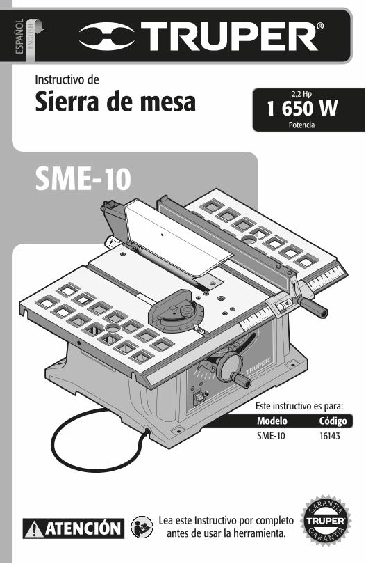
Instructivo de
Sierra de mesa
SME-10
Modelo CódigoSME-10
Este instructivo es para:
16143
2,2 Hp
Potencia1 650 W
ATENCIÓN Lea este Instructivo por completoantes de usar la herramienta.
ESPA
ÑO
LEN
GLI
SH
Índice
2
Especificaciones técnicas
Requerimientos eléctricos
Advertencias generales de Seguridadpara herramientas eléctricas
Advertencias de Seguridadpara uso de sierras eléctricas
Partes
Montaje
Ajustes
Puesta en marcha
Operación
Mantenimiento
Solución de problemas
Plantilla para fabricar herramientaspara empujar las piezas de trabajo
Centros de Servicio Autorizados
Sucursales
Póliza de Garantía
3
3
4
5
6
6
8
10
10
12
13
14
15
16
16
SME-10
Guarde este instructivo para futuras referencias.
Los gráficos de este instructivo son para referencia, pueden variar del aspecto real de la
herramienta.
Para poder sacar el máximo provecho de la herramienta,
alargar su vida útil, hacer válida la garantía en caso de ser
necesario y evitar riesgos o lesiones graves, es fundamental
leer este instructivo por completo antes de usar la
herramienta.
ATENCIÓN
ESPAÑOL
P
SME-10
Especificaciones técnicas
Requerimientos eléctricos
16143
Carburo de tungsteno de 254 mm (10”) y 36 dientes
Clase 0
50 Hz / 60 Hz
Sierra de mesa
50 min de trabajo por 20 min de descanso. Máximo diario de 6 horas.
4800 r/min
13 A
1650 W (2,2 HP)
CódigoDescripción
654 mm (25-3/4”) x 406,4 mm (16”)Mesa de trabajoDisco
TensiónFrecuencia
Corrienteotencia
VelocidadCiclo de trabajo
16 AWG x 2C con temperatura de aislamiento de 75°CConductoresAislamiento
El cable de alimentación tiene sujeta-cables tipo: YLa clase de construcción de la herramienta es: Aislamiento principal.
La clase de aislamiento térmico de los devanados del motor: Clase B
127 V
Al operar herramientas eléctricas en exteriores, utilice una extensión aterrizada marcada como “Uso exterior” marca . Estas extensiones son especiales para el uso en exteriores y reducen el riesgo de sufrir una descarga eléctrica.
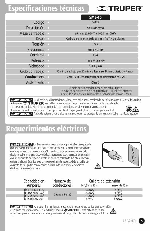
de 0 A hasta 10 Ade 10 A hasta 13 Ade 13 A hasta 15 Ade 15 A hasta 20 A
18 AWG16 AWG14 AWG8 AWG
16 AWG14 AWG12 AWG6 AWG
3 (uno a tierra)
de 1,8 m a 15 m | mayor de 15 mCapacidad en
AmperesNúmero deconductores
Calibre de extensión
ADVERTENCIA
Si el cable de alimentación se daña, éste debe ser reemplazado por el fabricante o Centro de Servicio Autorizado , con el fin de evitar algún riesgo de descarga o accidente considerable.La construcción del aislamiento eléctrico de esta herramienta es alterado por salpicaduras o derramamiento de líquidos durante su operación. No la exponga a la lluvia, líquidos y/o humedad.
Antes de obtener acceso a las terminales, todos los circuitos de alimentación deben ser desconectados.
ADVERTENCIA
ADVERTENCIA
ESPAÑOL 3
Las herramientas de aislamiento principal están equipadas con una clavija polarizada (una pata es más ancha que la otra). Esta clavija cabe en cualquier enchufe polarizado y sólo puede conectarse de una forma. Si la clavija no cabe en el enchufe, voltéelo. Si aún así no cabe, póngase en contacto con un electricista calificado o instale un enchufe polarizado. No altere la clavija en forma alguna. Este tipo de aislamiento elimina la necesidad de un cable de corriente de tres partes con conexión a tierra o de un sistema de corriente eléctrica con conexión a tierra.
ADVERTENCIA
4
Advertencias generales de seguridadpara herramientas eléctricas
ESPAÑOLEsta herramienta cumple con laNorma Oficial Mexicana (NOM).
Área de trabajoMantenga el área de trabajo limpia y bien iluminada.Las áreas desordenadas y obscuras son propensas a accidentes.
No maneje la herramienta en ambientes explosivos, como en presencia de líquido, gas o polvo inflamables.Las herramientas eléctricas producen chispas que pueden encendermaterial inflamable.
Mantenga alejados a los niños y curiosos cuando opere la herramienta.Las distracciones pueden hacer que pierda el control.
Seguridad eléctricaLa clavija de la herramienta debe coincidir con el tomacorrien-te. Nunca modifique una clavija. No use ningún tipo de adaptador para clavijas de herramientas puestas a tierra.Clavijas modificadas y enchufes diferentes aumentan el riesgo dechoque eléctrico.
Evite el contacto del cuerpo con superficies puestas a tierra como tuberías, radiadores, cocinas eléctricas y refrigeradores.Hay un mayor riesgo de choque eléctrico si el cuerpo está puesto a tierra.
No exponga la herramienta a la lluvia o condiciones de humedad.El agua que ingresa en la herramienta aumenta el riesgo de choque eléctrico.
No fuerce el cable. Nunca use el cable para transportar, levantar o desconectar la herramienta. Mantenga el cable lejos del calor, aceite, orillas afiladas o piezas en movimiento.Los cables dañados o enredados aumentan el riesgo de choque eléctrico.
Cuando maneje una herramienta en exteriores, use una extensión especial para uso en exteriores.El uso de una extensión adecuada para exteriores reduce el riesgo de choque eléctrico.
Si el uso de la herramienta en un lugar húmedo es inevitable, use una alimentación protegida por un interruptor de circuito de falla a tierra (GFCI).El uso de un GFCI reduce el riesgo de choque eléctrico.
Seguridad personalEsté alerta, vigile lo que está haciendo y use el sentido común cuando maneje una herramienta. No la use si está cansado o bajo la influencia de drogas, alcohol o medicamentos.Un momento de distracción mientras maneja la herramienta puedecausar un daño personal.
Use equipo de seguridad. Use siempre protección para los ojos.El uso de equipo de seguridad como lentes de seguridad, mascarilla antipolvo, zapatos antideslizantes, casco y protección para los oídos en condiciones apropiadas, reduce de manera significativa los daños personales.
Evite arranques accidentales. Asegúrese de que el interruptor está en posición “apagado” antes de conectar a la fuente de alimentación y/o a la batería o transportar la herramienta.Transportar herramientas eléctricas con el dedo sobre el interruptor oconectar herramientas eléctricas que tienen el interruptor en posición de “encendido” puede causar accidentes.
Retire cualquier llave o herramienta de ajuste antes de arrancar la herramienta eléctrica.Las llaves o herramientas que quedan en las partes rotativas de la herramienta pueden causar un daño personal.
No sobrepase su campo de acción. Mantenga ambos pies bien asentados sobre el suelo y conserve el equilibrio en todo momento.Esto permite un mejor control de la herramienta en situaciones inesperadas.
Vista adecuadamente. No vista ropa suelta o joyas. Mantenga su pelo, su ropa y guantes alejados de las piezas en movimiento.La ropa o el pelo sueltos o las joyas pueden quedar atrapados enlas piezas en movimiento.
En caso de contar con dispositivos de extracción y recolección de polvo conectados a la herramienta, verifique sus conexiones y úselos correctamente.El uso de estos dispositivos reduce los riesgos relacionados con el polvo.
Uso y cuidados de la herramientaNo fuerce la herramienta. Use la herramienta adecuada para el trabajo a realizar.La herramienta adecuada hace un trabajo mejor y más seguro cuandose usa al ritmo para el que fue diseñado.
No use la herramienta si el interruptor no funciona.Cualquier herramienta eléctrica que no pueda encenderse oapagarse es peligrosa y debe repararse antes de ser operada.
Desconecte la herramienta de la fuente de alimentación y/o de la batería antes de efectuar cualquier ajuste, cambiar accesorios o almacenarla.Estas medidas reducen el riesgo de arrancar la herramienta accidentalmente.
Almacene las herramientas fuera del alcance de los niños y no permita su manejo por personas no familiarizadas con las herramientas o con las instrucciones.Las herramientas eléctricas son peligrosas en manos no entrenadas.
Déle mantenimiento a la herramienta. Compruebe que las partes móviles no estén desalineadas o trabadas, que nohaya piezas rotas u otras condiciones que puedan afectar su operación. Repare cualquier daño antes de usar la herramienta.Muchos accidentes son causados por el escaso mantenimiento de las herramientas.
Mantenga los accesorios de corte afilados y limpios.Los accesorios de corte en buenas condiciones son menos probables de trabarse y más fáciles de controlar.
Use la herramienta, sus componentes y accesorios de acuerdo con estas instrucciones y de la manera prevista para el tipo de herramienta, en condiciones de trabajo adecuadas.El uso de la herramienta para aplicaciones diferentes para las queestá diseñada podría causar una situación de peligro.
ServicioRepare la herramienta en un Centro de Servicio Autorizado usando sólo piezas de repuesto idénticas.Para mantener la seguridad de la herramienta.
La máquina no debe de ser utilizada por niños ni por personas con capacidades físicas, sensoriales o mentales reducidas; tampoco por personas sin experiencia o conocimientos en su uso, a menos que estén supervisadas por una persona responsable de su seguridad o reciban instrucciones previas sobre el uso de la máquina.Los niños deben de estar bajo supervisión para asegurarse de que no jueguen con la máquina. Se debe de mantener una estricta supervisión si niños o personas discapacitadas llegan a utilizar cualquier tipo de aparato electrodoméstico o estén cerca de él.
¡ADVERTENCIA! Lea detenidamente todas las advertencias de seguridad y todas las instrucciones que se enlistan a continuación. La omisión de alguna de ellas puede dar como resultado un choque eléctrico, incendio y/o daño serio. Conserve las advertencias y las instrucciones para futuras referencias.
5
Advertencias de Seguridadpara uso de sierras eléctricas
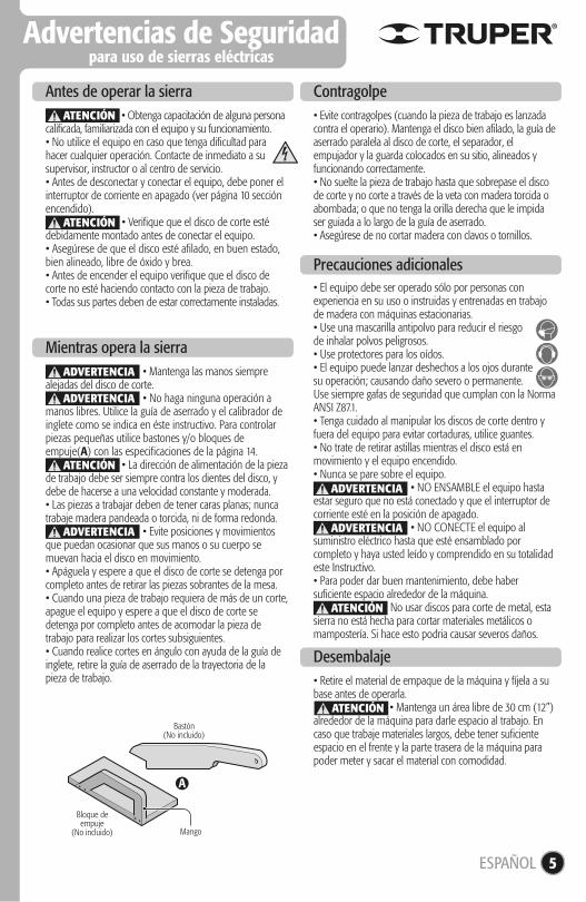
• Retire el material de empaque de la máquina y fíjela a su base antes de operarla. • Mantenga un área libre de 30 cm (12”) alrededor de la máquina para darle espacio al trabajo. En caso que trabaje materiales largos, debe tener suficiente espacio en el frente y la parte trasera de la máquina para poder meter y sacar el material con comodidad.
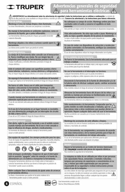
• Mantenga las manos siempre alejadas del disco de corte. • No haga ninguna operación a manos libres. Utilice la guía de aserrado y el calibrador de inglete como se indica en éste instructivo. Para controlar piezas pequeñas utilice bastones y/o bloques de empuje(A) con las especificaciones de la página 14. • La dirección de alimentación de la pieza de trabajo debe ser siempre contra los dientes del disco, y debe de hacerse a una velocidad constante y moderada.• Las piezas a trabajar deben de tener caras planas; nunca trabaje madera pandeada o torcida, ni de forma redonda. • Evite posiciones y movimientos que puedan ocasionar que sus manos o su cuerpo se muevan hacia el disco en movimiento.• Apáguela y espere a que el disco de corte se detenga por completo antes de retirar las piezas sobrantes de la mesa.• Cuando una pieza de trabajo requiera de más de un corte, apague el equipo y espere a que el disco de corte se detenga por completo antes de acomodar la pieza de trabajo para realizar los cortes subsiguientes.• Cuando realice cortes en ángulo con ayuda de la guía de inglete, retire la guía de aserrado de la trayectoria de la pieza de trabajo.
• Obtenga capacitación de alguna persona calificada, familiarizada con el equipo y su funcionamiento.• No utilice el equipo en caso que tenga dificultad para hacer cualquier operación. Contacte de inmediato a su supervisor, instructor o al centro de servicio.• Antes de desconectar y conectar el equipo, debe poner el interruptor de corriente en apagado (ver página 10 sección encendido). • Verifique que el disco de corte esté debidamente montado antes de conectar el equipo.• Asegúrese de que el disco esté afilado, en buen estado, bien alineado, libre de óxido y brea.• Antes de encender el equipo verifique que el disco de corte no esté haciendo contacto con la pieza de trabajo.• Todas sus partes deben de estar correctamente instaladas.
Antes de operar la sierra
Mientras opera la sierra
• Evite contragolpes (cuando la pieza de trabajo es lanzada contra el operario). Mantenga el disco bien afilado, la guía de aserrado paralela al disco de corte, el separador, el empujador y la guarda colocados en su sitio, alineados y funcionando correctamente.• No suelte la pieza de trabajo hasta que sobrepase el disco de corte y no corte a través de la veta con madera torcida o abombada; o que no tenga la orilla derecha que le impida ser guiada a lo largo de la guía de aserrado.• Asegúrese de no cortar madera con clavos o tornillos.
Contragolpe
Precauciones adicionales
Desembalaje
A
Bastón(No incluido)
Mango
Bloque deempuje
(No incluido)
ATENCIÓN
ATENCIÓN
ATENCIÓN
ADVERTENCIA
ADVERTENCIA
ADVERTENCIA
ATENCIÓN
• El equipo debe ser operado sólo por personas con experiencia en su uso o instruidas y entrenadas en trabajo de madera con máquinas estacionarias.• Use una mascarilla antipolvo para reducir el riesgode inhalar polvos peligrosos.• Use protectores para los oídos.• El equipo puede lanzar deshechos a los ojos durantesu operación; causando daño severo o permanente.Use siempre gafas de seguridad que cumplan con la Norma ANSI Z87.1.• Tenga cuidado al manipular los discos de corte dentro y fuera del equipo para evitar cortaduras, utilice guantes.• No trate de retirar astillas mientras el disco está en movimiento y el equipo encendido.• Nunca se pare sobre el equipo. • NO ENSAMBLE el equipo hasta estar seguro que no está conectado y que el interruptor de corriente esté en la posición de apagado. • NO CONECTE el equipo al suministro eléctrico hasta que esté ensamblado por completo y haya usted leído y comprendido en su totalidad este Instructivo.• Para poder dar buen mantenimiento, debe haber suficiente espacio alrededor de la máquina. No usar discos para corte de metal, esta sierra no está hecha para cortar materiales metálicos o mampostería. Si hace esto podria causar severos daños.
ADVERTENCIA
ADVERTENCIA
ESPAÑOL
ATENCIÓN
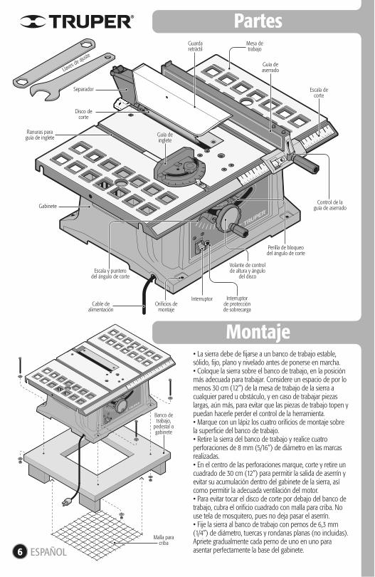
Partes
Montaje
Guardaretráctil
Separador
Gabinete
Cable dealimentación
Disco decorte
Mesa detrabajo
Interruptor Interruptorde protecciónde sobrecarga
Guía deinglete
Llaves de aju
ste
Guía deaserrado
Escala decorte
Banco detrabajo,
pedestal ogabinete
Malla paracriba
Ranuras paraguía de inglete
6
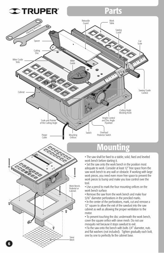
• La sierra debe de fijarse a un banco de trabajo estable, sólido, fijo, plano y nivelado antes de ponerse en marcha.• Coloque la sierra sobre el banco de trabajo, en la posición más adecuada para trabajar. Considere un espacio de por lo menos 30 cm (12”) de la mesa de trabajo de la sierra a cualquier pared u obstáculo, y en caso de trabajar piezas largas, aún más, para evitar que las piezas de trabajo topen y puedan hacerle perder el control de la herramienta.• Marque con un lápiz los cuatro orificios de montaje sobre la superficie del banco de trabajo.• Retire la sierra del banco de trabajo y realice cuatro perforaciones de 8 mm (5/16”) de diámetro en las marcas realizadas.• En el centro de las perforaciones marque, corte y retire un cuadrado de 30 cm (12”) para permitir la salida de aserrín y evitar su acumulación dentro del gabinete de la sierra, así como permitir la adecuada ventilación del motor.• Para evitar tocar el disco de corte por debajo del banco de trabajo, cubra el orificio cuadrado con malla para criba. No use tela de mosquitero, pues no deja pasar el aserrín.• Fije la sierra al banco de trabajo con pernos de 6,3 mm (1/4”) de diámetro, tuercas y rondanas planas (no incluidas). Apriete gradualmente cada perno de uno en uno para asentar perfectamente la base del gabinete.
Volante de controlde altura y ángulo
del disco
Perilla de bloqueodel ángulo de corte
Escala y punterodel ángulo de corte
Control de laguía de aserrado
Orificios demontaje
ESPAÑOL
7
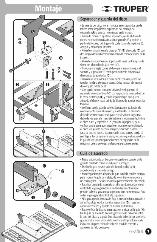
Montaje
Guía de aserrado
• La guarda del disco viene montada en el separador desde fábrica. Para simplificar la explicación del montaje del separador (A) la guarda no se ilustra en la imagen.• Antes de montar o ajustar el separador, ajuste el disco de corte a su posición más alta, a un ángulo de 0°, y apriete la perilla de bloqueo del ángulo de corte (consulte la página 8). Apague y desconecte la sierra.• Atornille manualmente la pieza en “L” (B) al soporte (C) con dos juegos de tornillo y rondana dentada como se indica en la imagen.• Atornille manualmente el soporte a la mesa de trabajo de la sierra con el tornillo de 50,8 mm (2”).• Coloque una regla contra el disco para asegurarse que el soporte y la pieza en “L” estén perfectamente alineados al disco antes de apretarlos (D).• Atornille el separador a la pieza en “L” con dos juegos de tornillo, rondana dentada y tuerca. Debe quedar alineado al disco y justo detrás de él. • Con ayuda de una escuadra universal verifique que el separador se encuentre a 90° con respecto de la superficie de la mesa de trabajo (E) y con la regla verifique que quede alineado al disco y justo detrás de él antes de apretar todos los tornillos.• Verifique que la guarda opere adecuadamente. Levántela manualmente unos 10 cm (4”) y suéltela (F). La elevación debe de sentirse suave y sin pausas, y al soltarse la guarda debe de regresar a la mesa de trabajo inmediatamente. Incline el disco a 45° y regréselo a 0° (consulte la página 8) para verificar que el separador quede en todo momento alineado al disco y la guarda queden siempre cubriendo el disco. En caso de que no suceda cualquiera de estos puntos, corrija el montaje antes de operar la sierra, recuerde que el separador y la guarda son los principales sistemas de seguridad de la máquina, que lo protegen de lesiones personales serias.
• Retire la tuerca de embarque y ensamble el control de la guía de aserrado como se indica en la imagen.• Deslice la guía de aserrado del lado derecho de la superficie de la mesa de trabajo.• Mantenga siempre alineada la guía paralela con las ranuras para montar la guía de inglete, de lo contrario se expone a un contragolpe. Use una escuadra para verificar la alineación.• Para fijar la guía de aserrado en el lugar deseado apriete el control de la guía girándolo a la derecha mientras hace presión sobre la guía en su lugar para que no se mueva. Para soltar la guía gire el control a la izquierda.• Si la guía queda demasiado floja o cuesta trabajo ajustarla o alinearla, afloje los dos tornillos superiores (G), haga los ajustes necesarios y apriete de nuevo los tornillos.• Para verificar la distancia marcada en el visor de la guía (H), fije la guía de aserrado en su lugar y mida la distancia entre la cara del disco y la guía. Esta distancia debe de ser la misma que se indica en el visor, de lo contrario afloje el tornillo del indicador (I) para colocarlo sobre la medida correcta y apriete el tornillo de nuevo.
Separador y guarda del disco
C
G
H
I
D E
F
B
A
ESPAÑOL
8
Montaje
Ajustes
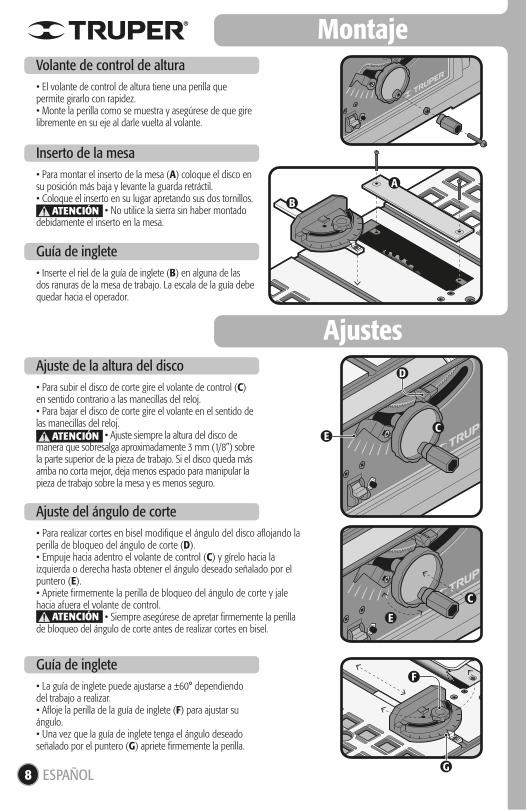
• El volante de control de altura tiene una perilla que permite girarlo con rapidez.• Monte la perilla como se muestra y asegúrese de que gire libremente en su eje al darle vuelta al volante.
Volante de control de altura
• Para montar el inserto de la mesa (A) coloque el disco en su posición más baja y levante la guarda retráctil.• Coloque el inserto en su lugar apretando sus dos tornillos. • No utilice la sierra sin haber montado debidamente el inserto en la mesa.
Inserto de la mesa
• Inserte el riel de la guía de inglete (B) en alguna de las dos ranuras de la mesa de trabajo. La escala de la guía debe quedar hacia el operador.
Guía de inglete
• La guía de inglete puede ajustarse a ±60° dependiendo del trabajo a realizar.• Afloje la perilla de la guía de inglete (F) para ajustar su ángulo.• Una vez que la guía de inglete tenga el ángulo deseado señalado por el puntero (G) apriete firmemente la perilla.
Guía de inglete
• Para subir el disco de corte gire el volante de control (C) en sentido contrario a las manecillas del reloj.• Para bajar el disco de corte gire el volante en el sentido de las manecillas del reloj. • Ajuste siempre la altura del disco de manera que sobresalga aproximadamente 3 mm (1/8”) sobre la parte superior de la pieza de trabajo. Si el disco queda más arriba no corta mejor, deja menos espacio para manipular la pieza de trabajo sobre la mesa y es menos seguro.
Ajuste de la altura del disco
• Para realizar cortes en bisel modifique el ángulo del disco aflojando la perilla de bloqueo del ángulo de corte (D).• Empuje hacia adentro el volante de control (C) y gírelo hacia la izquierda o derecha hasta obtener el ángulo deseado señalado por el puntero (E).• Apriete firmemente la perilla de bloqueo del ángulo de corte y jale hacia afuera el volante de control. • Siempre asegúrese de apretar firmemente la perilla de bloqueo del ángulo de corte antes de realizar cortes en bisel.
Ajuste del ángulo de corte
E
F
G
D
C
C
B
A
ATENCIÓN
ATENCIÓN
ATENCIÓN
ESPAÑOL
E
9
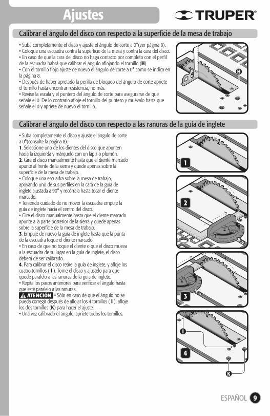
Ajustes
• Suba completamente el disco y ajuste el ángulo de corte a 0°(ver página 8).• Coloque una escuadra contra la superficie de la mesa y contra la cara del disco.• En caso de que la cara del disco no haga contacto por completo con el perfil de la escuadra habrá que calibrar el ángulo aflojando el tornillo (H).• Con el tornillo flojo ajuste de nuevo el ángulo de corte a 0° como se indica en la página 8.• Después de haber apretado la perilla de bloqueo del ángulo de corte apriete el tornillo hasta encontrar resistencia, no más.• Revise la escala y el puntero del ángulo de corte para asegurarse de que señale el 0. De lo contrario afloje el tornillo del puntero y muévalo hasta que señale el 0 y apriete de nuevo el tornillo.
Calibrar el ángulo del disco con respecto a la superficie de la mesa de trabajo
• Suba completamente el disco y ajuste el ángulo de corte a 0°(consulte la página 8).1. Seleccione uno de los dientes del disco que apunten hacia la izquierda y márquelo con un lápiz o plumón.2. Gire el disco manualmente hasta que el diente marcado apunte al frente de la sierra y quede apenas sobre la superficie de la mesa de trabajo.• Coloque una escuadra sobre la mesa de trabajo, apoyando uno de sus perfiles en la cara de la guía de inglete ajustada a 90° y recórrala hasta tocar el diente marcado.• Teniendo cuidado de no mover la escuadra empuje la guía de inglete hacia el centro del disco.• Gire el disco manualmente hasta que el diente marcado apunte a la parte posterior de la sierra y quede apenas sobre la superficie de la mesa de trabajo.3. Empuje de nuevo la guía de inglete hasta que la punta de la escuadra toque el diente marcado.• En caso de que no toque el diente o que el disco mueva a la escuadra de su lugar en la guía de inglete, el disco deberá de ser calibrado.4. Para calibrar el disco retire la guía de inglete, y afloje los cuatro tornillos ( I ). Tome el disco y ajústelo para que quede paralelo a las ranuras de la guía de inglete.• Repita los pasos anteriores para verificar el ángulo hasta que esté paralelo a las ranuras. • Sólo en caso de que el ángulo no se pueda corregir después de aflojar los 4 tornillos ( I ), afloje los dos tornillos (K) para hacer el ajuste.• Una vez calibrado el ángulo, apriete todos los tornillos.
Calibrar el ángulo del disco con respecto a las ranuras de la guía de inglete
H
I
K
1
2
3
4
ATENCIÓN
ESPAÑOL
A
D
Puesta en marcha
Operación
10
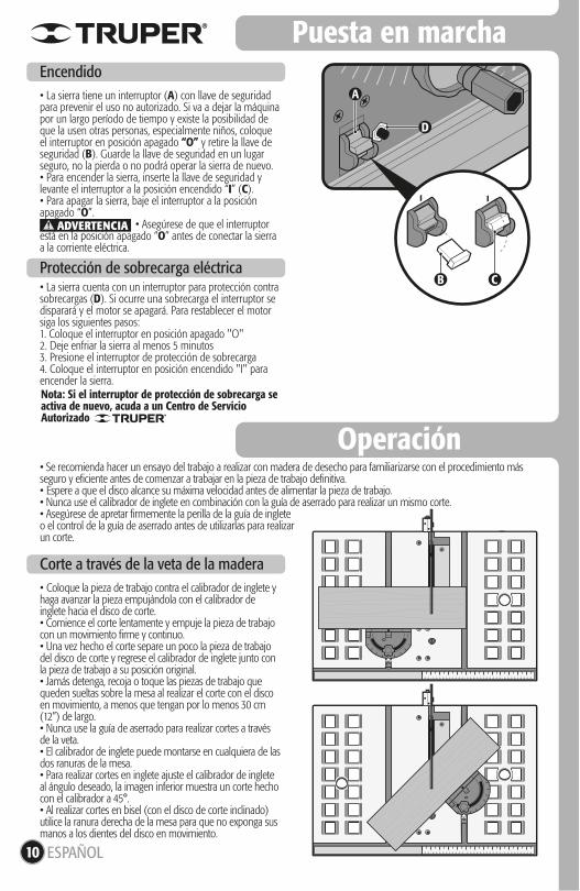
• La sierra tiene un interruptor (A) con llave de seguridad para prevenir el uso no autorizado. Si va a dejar la máquina por un largo período de tiempo y existe la posibilidad de que la usen otras personas, especialmente niños, coloque el interruptor en posición apagado “O” y retire la llave de seguridad (B). Guarde la llave de seguridad en un lugar seguro, no la pierda o no podrá operar la sierra de nuevo.• Para encender la sierra, inserte la llave de seguridad y levante el interruptor a la posición encendido “I” (C). • Para apagar la sierra, baje el interruptor a la posición apagado “O”. • Asegúrese de que el interruptor está en la posición apagado “O” antes de conectar la sierra a la corriente eléctrica.
Encendido
• Coloque la pieza de trabajo contra el calibrador de inglete y haga avanzar la pieza empujándola con el calibrador de inglete hacia el disco de corte.• Comience el corte lentamente y empuje la pieza de trabajo con un movimiento firme y continuo.• Una vez hecho el corte separe un poco la pieza de trabajo del disco de corte y regrese el calibrador de inglete junto con la pieza de trabajo a su posición original.• Jamás detenga, recoja o toque las piezas de trabajo que queden sueltas sobre la mesa al realizar el corte con el disco en movimiento, a menos que tengan por lo menos 30 cm (12”) de largo.• Nunca use la guía de aserrado para realizar cortes a través de la veta.• El calibrador de inglete puede montarse en cualquiera de las dos ranuras de la mesa.• Para realizar cortes en inglete ajuste el calibrador de inglete al ángulo deseado, la imagen inferior muestra un corte hecho con el calibrador a 45°.• Al realizar cortes en bisel (con el disco de corte inclinado) utilice la ranura derecha de la mesa para que no exponga sus manos a los dientes del disco en movimiento.
Corte a través de la veta de la madera
• La sierra cuenta con un interruptor para protección contra sobrecargas (D). Si ocurre una sobrecarga el interruptor se disparará y el motor se apagará. Para restablecer el motor siga los siguientes pasos:1. Coloque el interruptor en posición apagado "O" 2. Deje enfriar la sierra al menos 5 minutos3. Presione el interruptor de protección de sobrecarga4. Coloque el interruptor en posición encendido "I" para encender la sierra.
Protección de sobrecarga eléctrica
• Se recomienda hacer un ensayo del trabajo a realizar con madera de desecho para familiarizarse con el procedimiento más seguro y eficiente antes de comenzar a trabajar en la pieza de trabajo definitiva.• Espere a que el disco alcance su máxima velocidad antes de alimentar la pieza de trabajo.• Nunca use el calibrador de inglete en combinación con la guía de aserrado para realizar un mismo corte.• Asegúrese de apretar firmemente la perilla de la guía de inglete o el control de la guía de aserrado antes de utilizarlas para realizar un corte.
ADVERTENCIA
B C
ESPAÑOL
Nota: Si el interruptor de protección de sobrecarga se activa de nuevo, acuda a un Centro de Servicio Autorizado
E
F
Operación
11
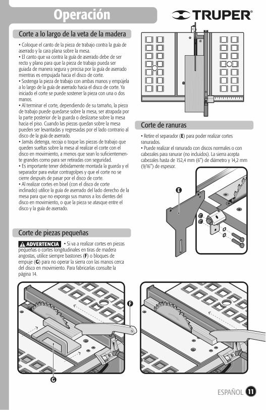
• Coloque el canto de la pieza de trabajo contra la guía de aserrado y la cara plana sobre la mesa.• El canto que va contra la guía de aserrado debe de ser recto y plano para que la pieza de trabajo pueda ser guiada de manera segura y precisa por la guía de aserrado mientras es empujada hacia el disco de corte.• Sostenga la pieza de trabajo con ambas manos y empújela a lo largo de la guía de aserrado hacia el disco de corte. Ya iniciado el corte se puede sostener la pieza con una o dos manos.• Al terminar el corte, dependiendo de su tamaño, la pieza de trabajo puede quedarse sobre la mesa, ser atrapada por la parte posterior de la guarda o deslizarse sobre la mesa hacia el piso. Cuando las piezas quedan sobre la mesa pueden ser levantadas y regresadas por el lado contrario al disco de la guía de aserrado.• Jamás detenga, recoja o toque las piezas de trabajo que queden sueltas sobre la mesa al realizar el corte con el disco en movimiento, a menos que sean lo suficientemen-te grandes como para ser retiradas con seguridad.• Es importante tener debidamente montada la guarda y el separador para evitar contragolpes y que el corte no se cierre después de pasar por el disco de corte.• Al realizar cortes en bisel (con el disco de corte inclinado) utilice la guía de aserrado del lado derecho de la mesa para que no exponga sus manos a los dientes del disco en movimiento, o que la pieza se atasque entre el disco y la guía de aserrado.
Corte a lo largo de la veta de la madera
• Si va a realizar cortes en piezas pequeñas o cortes longitudinales en tiras de madera angostas, utilice siempre bastones (F) o bloques de empuje (G) para no operar la sierra con las manos cerca del disco en movimiento. Para fabricarlas consulte la página 14.
Corte de piezas pequeñas
• Retire el separador (E) para poder realizar cortes ranurados.• Puede realizar el ranurado con discos normales o con cabezales para ranurar (no incluidos). La sierra acepta cabezales hasta de 152,4 mm (6”) de diámetro y 14,2 mm (9/16”) de espesor.
Corte de ranuras
ESPAÑOL
G
ADVERTENCIA
• El servicio debe ser realizado únicamente por personal de un Centro de Servicio Autorizado• Servicios y mantenimientos realizados por personas no calificadas puede resultar peligrosos y llegar a ocasionar daños personales además de invalidar la garantía del producto.
• Los carbones deben revisarse periódicamente, y ser reemplazados siempre por un Centro de Servicio Autorizado cuando se hayan desgastado.• Después de su reemplazo, pida que se revise si los nuevos carbones se mueven libremente en el porta-carbón y que enciendan la herramienta 5 minutos para emparejar el contacto de los carbones y el conmutador.• Sólo se deben de usar carbones de repuesto originales, diseñados específicamente con la dureza y la resistencia eléctrica adecuadas para cada tipo de motor. Los carbones fuera de especificaciones pueden dañar el motor.• Cuando se haga el cambio de carbones siempre deben reemplazarse los dos carbones.
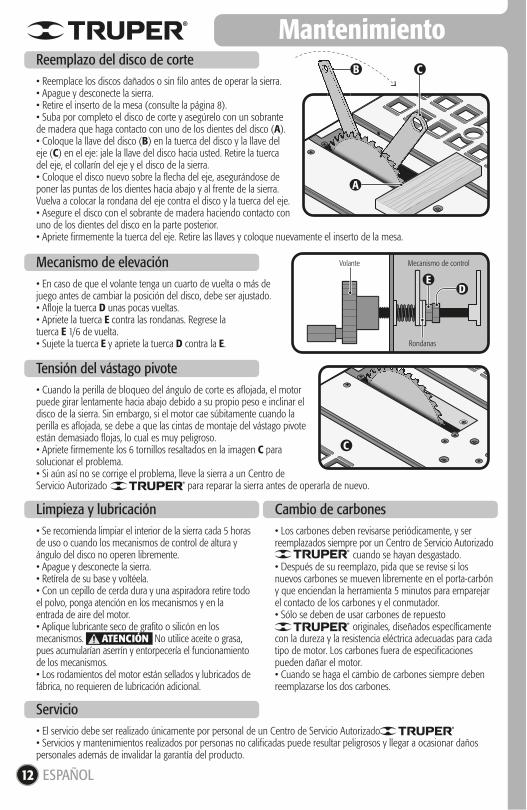
• Se recomienda limpiar el interior de la sierra cada 5 horas de uso o cuando los mecanismos de control de altura y ángulo del disco no operen libremente.• Apague y desconecte la sierra.• Retírela de su base y voltéela.• Con un cepillo de cerda dura y una aspiradora retire todo el polvo, ponga atención en los mecanismos y en la entrada de aire del motor.• Aplique lubricante seco de grafito o silicón en los mecanismos. No utilice aceite o grasa, pues acumularían aserrín y entorpecería el funcionamiento de los mecanismos.• Los rodamientos del motor están sellados y lubricados de fábrica, no requieren de lubricación adicional.
Volante
Rondanas
Mecanismo de control
B C
A
D
C
E
Mantenimiento
12
• Reemplace los discos dañados o sin filo antes de operar la sierra.• Apague y desconecte la sierra.• Retire el inserto de la mesa (consulte la página 8).• Suba por completo el disco de corte y asegúrelo con un sobrante de madera que haga contacto con uno de los dientes del disco (A).• Coloque la llave del disco (B) en la tuerca del disco y la llave del eje (C) en el eje: jale la llave del disco hacia usted. Retire la tuerca del eje, el collarín del eje y el disco de la sierra.• Coloque el disco nuevo sobre la flecha del eje, asegurándose de poner las puntas de los dientes hacia abajo y al frente de la sierra. Vuelva a colocar la rondana del eje contra el disco y la tuerca del eje.• Asegure el disco con el sobrante de madera haciendo contacto con uno de los dientes del disco en la parte posterior.• Apriete firmemente la tuerca del eje. Retire las llaves y coloque nuevamente el inserto de la mesa.
Reemplazo del disco de corte
Limpieza y lubricación
Servicio
• En caso de que el volante tenga un cuarto de vuelta o más de juego antes de cambiar la posición del disco, debe ser ajustado.• Afloje la tuerca D unas pocas vueltas.• Apriete la tuerca E contra las rondanas. Regrese latuerca E 1/6 de vuelta.• Sujete la tuerca E y apriete la tuerca D contra la E.
Mecanismo de elevación
• Cuando la perilla de bloqueo del ángulo de corte es aflojada, el motor puede girar lentamente hacia abajo debido a su propio peso e inclinar el disco de la sierra. Sin embargo, si el motor cae súbitamente cuando la perilla es aflojada, se debe a que las cintas de montaje del vástago pivote están demasiado flojas, lo cual es muy peligroso.• Apriete firmemente los 6 tornillos resaltados en la imagen C para solucionar el problema.• Si aún así no se corrige el problema, lleve la sierra a un Centro de Servicio Autorizado para reparar la sierra antes de operarla de nuevo.
Tensión del vástago pivote
Cambio de carbones
ATENCIÓN
ESPAÑOL
13
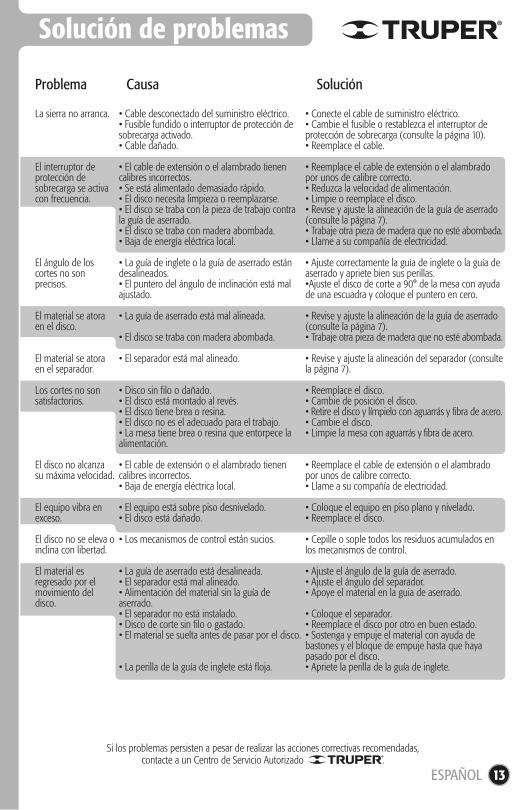
Solución de problemas
La sierra no arranca.
El interruptor de protección de sobrecarga se activa con frecuencia.
El ángulo de los cortes no son precisos.
El material se atora en el disco.
El material se atora en el separador.
Los cortes no son satisfactorios.
El disco no alcanza su máxima velocidad.
El equipo vibra en exceso.
El disco no se eleva o inclina con libertad.
El material es regresado por el movimiento del disco.
• Cable desconectado del suministro eléctrico.• Fusible fundido o interruptor de protección de sobrecarga activado.• Cable dañado.
• El cable de extensión o el alambrado tienen calibres incorrectos.• Se está alimentado demasiado rápido.• El disco necesita limpieza o reemplazarse.• El disco se traba con la pieza de trabajo contra la guía de aserrado.• El disco se traba con madera abombada.• Baja de energía eléctrica local.
• La guía de inglete o la guía de aserrado están desalineados.• El puntero del ángulo de inclinación está mal ajustado.
• La guía de aserrado está mal alineada.
• El disco se traba con madera abombada.
• El separador está mal alineado.
• Disco sin filo o dañado.• El disco está montado al revés.• El disco tiene brea o resina.• El disco no es el adecuado para el trabajo.• La mesa tiene brea o resina que entorpece la alimentación.
• El cable de extensión o el alambrado tienen calibres incorrectos.• Baja de energía eléctrica local.
• El equipo está sobre piso desnivelado.• El disco está dañado.
• Los mecanismos de control están sucios.
• La guía de aserrado está desalineada.• El separador está mal alineado.• Alimentación del material sin la guía de aserrado.• El separador no está instalado.• Disco de corte sin filo o gastado.• El material se suelta antes de pasar por el disco.
• La perilla de la guía de inglete está floja.
• Conecte el cable de suministro eléctrico.• Cambie el fusible o restablezca el interruptor de protección de sobrecarga (consulte la página 10).• Reemplace el cable.
• Reemplace el cable de extensión o el alambrado por unos de calibre correcto.• Reduzca la velocidad de alimentación.• Limpie o reemplace el disco.• Revise y ajuste la alineación de la guía de aserrado (consulte la página 7).• Trabaje otra pieza de madera que no esté abombada.• Llame a su compañía de electricidad.
• Ajuste correctamente la guía de inglete o la guía de aserrado y apriete bien sus perillas.•Ajuste el disco de corte a 90° de la mesa con ayuda de una escuadra y coloque el puntero en cero.
• Revise y ajuste la alineación de la guía de aserrado (consulte la página 7).• Trabaje otra pieza de madera que no esté abombada.
• Revise y ajuste la alineación del separador (consulte la página 7).
• Reemplace el disco.• Cambie de posición el disco.• Retire el disco y límpielo con aguarrás y fibra de acero.• Cambie el disco.• Limpie la mesa con aguarrás y fibra de acero.
• Reemplace el cable de extensión o el alambrado por unos de calibre correcto.• Llame a su compañía de electricidad.
• Coloque el equipo en piso plano y nivelado.• Reemplace el disco.
• Cepille o sople todos los residuos acumulados en los mecanismos de control.
• Ajuste el ángulo de la guía de aserrado.• Ajuste el ángulo del separador.• Apoye el material en la guia de aserrado.
• Coloque el separador.• Reemplace el disco por otro en buen estado.• Sostenga y empuje el material con ayuda de bastones y el bloque de empuje hasta que haya pasado por el disco.• Apriete la perilla de la guía de inglete.
Problema Causa Solución
Si los problemas persisten a pesar de realizar las acciones correctivas recomendadas,contacte a un Centro de Servicio Autorizado .
ESPAÑOL
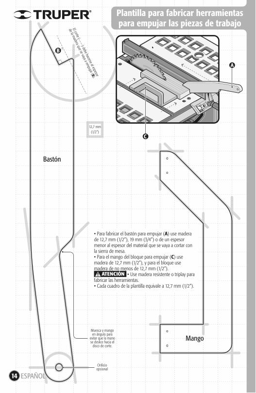
Muesca y mangoen ángulo para
evitar que la manose deslice hacia el
disco de corte.
Orificioopcional
14 ESPAÑOL
Plantilla para fabricar herramientaspara empujar las piezas de trabajo
12,7 mm(1/2”)
• Para fabricar el bastón para empujar (A) use madera de 12,7 mm (1/2”), 19 mm (3/4”) o de un espesor menor al espesor del material que se vaya a cortar con la sierra de mesa.• Para el mango del bloque para empujar (C) use madera de 12,7 mm (1/2”), y para el bloque use madera de no menos de 12,7 mm (1/2”). • Use madera resistente o triplay para fabricar las herramientas.• Cada cuadro de la plantilla equivale a 12,7 mm (1/2”).
ATENCIÓN
El corte ( ) debe hacerse al espesor
de la madera que se vaya a em
pujar (B).
B
A
C
Bastón
Mango
Centros de Servicio Autorizados
15ESPAÑOL
671615 SUPER TOOLSZARAGOZA NO. 1205, COL. EL SOL, AGUASCALIENTES, AGS. TEL.: 01(449) 996-5978
670796 CONTRURENTASPROL. I. ZARAGOZA Y MÁRQUEZ DE LEÓN,COL. 5 DE FEBRERO, SAN JOSÉ DEL CABO, BCSTEL.: 01(624) 142-4595
670032 PROVINDAV. COLEGIO MILITAR No. 4307 A, COL. NOMBRE DE DIOS C.P. 31100, CHIHUAHUA, CHIH. TEL.: 01(614) 424-4000
671530 FERRETERÍA AMAYA S.A. DE C.V.AV. ORTIZ MENA No. 81, COL. CENTRO C.P. 33800 PARRAL, CHIH. TEL.: 01(627) 522-2600
670712 INDUSTRIAL FERRETERA DE MONCLOVA, S.A. DE C.V. BLVD. HAROLD R. PAPE No. 1000, COL. CENTRO C.P. 25700 MONCLOVA, COAH.TEL.: 01(866) 632-0174 FAX: 01(866) 633-0719
671742 SURTIDORA DE FERRETERÍA AV. ANTONIO LEAÑO ÁLVAREZ No. 527 COL. PONCIANO ARRIAGA. TECOMÁN, TEL.: 01(313) 324-2000 y 7666 FAX: 325-2700
671770 TORNILLOS Y HERRAMIENTAS PINEDA 17 PONIENTE No. 20-A, COL. CENTRO TAPACHULA, CHIAPASTEL.: 01(962) 626-2807
671709 FERRETERA MANDIOLA, S.A. DE C.V. 5a NORTE PONIENTE No. 1615-B, COL. MOCTEZUMA,C.P. 29000, TUXTLA GUTIÉRREZ, TEL.: 01(961) 602-1544
671747 CENTRO DE SERVICIO DEL SURESTE LIBRAMIENTO SUR ORIENTE S/N km 6.5COL. TRABAJADORES, TUXTLA GUTIÉRREZ, CHIAPASTEL.: 01(961) 223-2350
670515 FERRETERÍA CASUARAMÓN CORONA No. 72, COL. BARRIO SANTA LUCÍA C.P. 29250, SAN CRISTOBAL DE LAS CASAS, CHIS.TEL.: 01(967) 678-6283
671601 MATERIALES DE CONSTRUCCIÓN DE LOS ALTOS, S.A. DE C.V. FRANCISCO I. MADERO No.5, COL. CENTRO, C.P. 29200, SAN CRISTOBAL DE LAS CASAS, CHIS.
671730 MATERIALES Y ACEROS BALAM S.A. PERIFERICO NORTE-PONIENTE No. 50 COL. BISMAR, SN. CRISTOBAL DE LAS CASAS TEL.: 01 (967) 678-6162 y 7422
670781 PREFABRICADOS DE PALENQUE, S.A. DE C.V. km 1 CARRETERA PALENQUE - PAKAL-NÁ S/N ENTRADA LIENZO CHARRO C.P. 22960, PALENQUE, CHIS. TEL.: 01 (916) 345-1523 | 345-1533
671829 EL FUERTE DE LAS HERRAMIENTAS S.A. DE C.V. PONIENTE 140 No.618 LOCAL B, COL. INDUSTRIAL VALLEJO, AZCAPOTZALCO, C.P. 02300 TELS.: 01(55) 5587-7959 y 7731
670995 EL MONSTRUO DE CORREGIDORA S.A. DE C.V. CORREGIDORA No.22, COL. CENTRO C.P. 06060 CIUDAD DE MÉXICO TEL.: 01(55) 5522-4861 | 71 y01(55) 5522-5031, FAX: 01(55) 5522-5021
671370 ADMINISTRADORA FERRETERA, S.A. DE C.V. CORREGIDORA No. 76-A, COL. CENTRO C.P. 06060 CIUDAD DE MÉXICO TEL.: 01 (55) 5522-9976FAX: 01(55) 5522-9966
671131 CERRADA PINO SUAREZ No. 24, COL. ZONA ESCOLAR C.P. 07230, GUSTAVO A. MADERO, CIUDAD DE MÉXICO TEL.: 01(55) 2207-0882
671137 INGENIERÍA SUMINISTROS Y SERVICIOS INDUSTRIALES CALZADA DE GUADALUPE No.525-A, COL. ESTRELLA, C.P. 07810, GUSTAVO A. MADERO, CIUDAD DE MÉXICO TEL. Y FAX: 01(55) 5577-9331 | 5781-7079
670350 TORNILLOS ÁGUILA, S.A. DE C.V.MASURIO No. 200 ESQUINA GALIO, COL. LUIS ECHEVERRIA C.P. 34250, DURANGO, DGO.TEL.: 01(618) 817-1946 | 818-2655
671671ENRIQUE CARROLA ANTUNA NO. 406 COL. CIÉNEGA, DURANGO, DGO. TEL.: 01(618) 825-2710
671600 ABC DE MATERIALES, S.A. DE C.V. VENUSTIANO CARRANZA No. 104 COL. LOS ÁNGELES TOTOLCINGO, ACOLMAN, EDO. DE MÉXICOTEL.: 01(55) 2958-8504
671723 FERRETERA TECAMAC S.A. DE C.V.CARR. MEXICO-PACHUCA km 37.5 TECAMAC, EDO. DE MÉXICO. TEL.: 5934-6396 Y 5934-6271
671765 TLAPALERIA CRUZAV. CUAUHTEMOC No. 3 COL. BO. SAN JOSÉ, TEQUIXQUIAC, TEL.: 591-91-203-44
671025 SERVICIO Y VENTA DE HERRAMIENTAS VGAV. DE LOS MAESTROS No. 14, COL. LEANDRO VALLE C.P.54040, TLANEPANTLA DE BAZ, EDO. DE MÉXICO, TEL.: 01(55) 2628-3120 Y FAX: 01(55) 5398-2104
670050 ABRASIVOS Y SOLDADURAS ESPECIALES DE TOLUCA ISABEL LA CATÓLICA SUR No. 101 ESQ. MIGUEL HIDALGO COL. STA. CLARA C.P. 50090, TOLUCA, EDO. DE MÉXICO, TEL.: 01(722) 773-1117 | 773-1116 | 214-9458, FAX: 01(722) 215-2145
670514AV. TEXCOCO No. 354, COL. METROPOLITANA 2A SECCIÓN C.P. 57740, CD. NEZAHUALCOYOTL, EDO. DE MÉXICO, TEL.: 01(55) 5792-4458
670150 COMPAÑÍA FERRETERA NUEVO MUNDOS.A. DE C.V. AV. MÉXICO - JAPÓN No. 225, CD. INDUSTRIAL C.P. 38010, CELAYA, GTO. TEL. Y FAX: 01(461) 617-7578 | 617-7579 | 617-7580 | 617-7588
670261 PROVEEDORES DE HERRAMIENTASSINALOA No. 39 COL. MIGUEL HIDALGOIRAPUATO, GTO. TELS.: 01(462) 626-3813, 124-8806 FAX: 01 (462) 623-0523
671492 HERRAMIENTAS Y SERVICIOS DE LEÓN S. DE R.L. DE C.V. LÓPEZ MATEOS ORIENTE No. 230, COL. CENTRO CP. 37000 LEÓN, GTO. TEL./FAX 01(477) 714-6514
671290 EL GRINGO LIBRAMIENTO SUR No. 609, COL. DEL SOL C.P. 37900 SAN LUIS DE LA PAZ, GTO. TEL. Y FAX: 01 (468) 688-4886
670926 DISTRIBUIDORA RAGASA, S.A. DE C.V.AV. LÁZARO CÁRDENAS No. 908, COL. CENTRO C.P. 40660 CD. ALTAMIRANO, GRO. TEL.: 01(767) 672-0843
671637LAS PALMERAS No. 48 COL. CENTRO, COYUCA DE BENÍTEZ, GRO. TEL.: 01(781) 452-0815
671677MARIANO ABASOLO S/N COL. OMETEPEC CENTRO, OMETEPEC, GRO.TEL.: 01(741) 412-1339
670915 MUNDO TOOL MÉXICO, S.A. DE C.V. ALLENDE No. 320, COL. CENTRO C.P. 42000, PACHUCA, HGO. TEL. Y FAX: 01(771) 715-0048
670640 SAN ANTONIO MATERIALES PARA CONSTRUCCIÓN CARR. MEXICO-PACHUCA km 81.5 COL. SAN ANTONIO EL DESMONTE, TEL.: 01(771) 711- 0732
670655 FERREPRECIOS, S.A. DE C.V. LIBERTAD ORIENTE No. 304 LOCAL 30, INTERIOR DE PASAJE ROBLEDO, COL. CENTRO, TULANCINGO, TEL. 01(775) 753-6615 y 16
670855 MAGNOCENTRO FERRETERO, S.A. DE C.V.AV. LA PAZ No.1180, COL. CENTRO, GUADALAJARA, JAL. TEL.: 01(33) 3658-1867 y 59FAX: 01(33) 3658-1870
670770 ACEROS Y MATERIALES DIAZ S.A. DE C.V. AV. FRANCISCO ZARCO No. 755, COL. FLORIDA C.P. 47800, OCOTLAN, JAL. TEL.: 01(392) 922-4740 | 922-0177
671737 EQUIPOS Y HERRAMIENTAS PROFESIONALES JOSÉ MANUEL DE HERRERA No. 149, COL. CENTRO, APATZINGÁN, TEL. 01(453) 534-2204
671766 SERVICIOS Y HERRAMIENTAS DEL SURAV. 22 DE OCTUBRE No. 303 COL. MIGUEL HIDALGO, APATZINGÁN, TEL. 01(453) 534-2033
671830 MOTOSIERRAS Y SERVICIOS DE MORELIA MORELOS NORTE No. 821 COL. CENTRO, MORELIA, C.P. 58000 TEL.: 01(443) 317-9482
670336 FERREMAQUINARIA INDUSTRIAL S.A. DE C.V. AV. LÁZARO CÁRDENAS No. 241, COL. CENTRO C.P. 60950, CD. LÁZARO CÁRDENAS, MICH.TEL.: 01(753) 532-0738 | 532-4396 | 532-2541 FAX: 01(753) 532-3366
670872 MATERIALES GARCÍA Y BARRAGÁN S.A. DE C,V. IGNACIO ZARAGOZA No. 187 B, COL. CENTRO,C.P. 61650, TACÁMBARO, MICH. TEL.: 01(459) 596-0190, FAX: 01(459) 596-0700
671130 HERRAMIENTAS Y SERVICIOS FORESTALES DE ZAMORA AV. JUÁREZ No. 213 OTE. ENTRE 5 DE MAYO Y AQUILES SERDAN, COL. CENTRO C.P. 59600, ZAMORA, MICH. TEL.: 01(351) 517-8420
670805 LA NUEVA FERRETERÍA TRUPERGENERAL PUEBLITA No. 356, COL. CENTRO C.P. 58600, ZACAPU, MICH. TEL.: 01(436) 363-3351
671115 HERRAMIENTAS Y SERVICIOS INDUSTRIALES DE ZITACUARO NETZAHUALCOYOTL NORTE No. 6, COL. MOCTEZUMA C.P. 61505, ZITACUARO, MICH.TEL.: 01(715) 151-3228
671664AVENIDA FRANCISCO VILLA NO. 31 COL. MORELOS, URUAPAN, MICH. TEL.: 01(452) 528-9536
671877 FERREMATERIALES DURAMAX km 100 CARR. MEXICO-ACAPULCO, COL. ALPUYECA, C.P. 62797TEL.: 01(777) 678-9069 TEL. / FAX: 01(777) 678-7956
671625 MARTÍNEZ BARRANCO, S.A. DE C.V. AV. LA PAZ No. 721 COL. CALIFORNIA, OAXACA TEL.: 01(951) 133-1521
671712 MUNDO MAKITA SÍMBOLOS PATRIOS No. 101,COL. ELISEO JIMÉNEZ RUÍZ, OAXACA, OAX
671782 MIFERRECARR. COSTERA DEL PACÍFICO No. 300, COL. LOS MANGALES, PUERTO ESCONDIDO TEL.: 01(954) 582-4218
671794 AGROBOMBAS ROSARIOS S.A. AV. INDEPENDENCIA No. 1323 COL. LA PIRAGUA, TUXTEPEC C.P. 68300 TEL.: 01(287) 875-1363
671420 DISTRIBUIDORA DE HERRAMIENTAS MANUALES ZAVALETA, S.A. DE C.V.RIVERA ATOYAC No. 325, COL. SANTA CRUZ BUENA VISTA, C.P. 72810, SAN ANDRÉS CHOLULA, PUE. TEL. / FAX: 01(222) 249-8592
671211 SERVITECAV. DE LA JUVENTUD No. 1103 ESQ. 7 SUR,COL. NICÓLAS BRAVO C.P. 75790, TEHUACAN, PUE. TEL. / FAX: 01(238) 371-7200
671822 TIENDA FIX TEHUACANAV. SEGUNDA DE MORELOS No. 303, COL. CENTRO, TEHUACÁN, TEL.: 01(238) 384-8640
670402 MOTORES Y HERRAMIENTAS ELÉCTRICAS AV. 6 No. 1004-B ESQ. CALLE 19, COL. LOMAS DE CASA BLANCA C.P. 76080, QUERETARO, QRO.TEL. Y FAX : 01(442) 167-4733
671265 FERRETERA PRADO HERRAMIENTAS S.A. DE C.V. AV. UNIVERSIDAD No. 325-A, COL. GRANJAS MANTHI C.P. 76808, SAN JUAN DEL RIO, QRO.TEL. / FAX : 01(427) 268-4544
670046 CENTRO FERRETERO DE CANCÚNAV. COMACALCO No. 12, COL. SUPERMANZANA 59 C.P. 77515, CANCÚN, Q. ROO.TEL.: 01(998) 886-8777 | 887-6616
671011ÁLVARO OBREGÓN No. 281-283 COL. CENTRO, CHETUMAL, QUINTANA ROO TEL.: 01(983) 833-2358
671732 MULTISIERRAS TALICUMI AVENIDA MIGUEL HIDALGO NO.221 COL. VENUSTIANO CARRANZA, CHETUMAL.
671636 95/24 MÉXICO, S.A. DE C.V. SUC. SLPAV. UNIVERSIDAD No. 1850 COL. EL PASEO, SAN LUIS POTOSÍ C.P. 78320 TEL. / FAX: 01(444) 822-4341
671642JACARANDAS S/N COL. DEL BOSQUE, GUASAVE, SIN. TEL.: 01(687) 871-2636
671045 FERRETERÍA LA ÚNICALÁZARO MERCADO No. 1234 COL. MUNICIPIO LIBRE C.P. 85080 CD. OBREGÓN, SON. TEL. / FAX: 01(644) 412-9836
671610 GRUPO VAQUEIRO FERRETERO, S.A. DE C.V. PERIFÉRICO CARLOS PELLICER CÁMARA No. 2810 COL. MIGUEL HIDALGO, VILLAHERMOSA, C.P. 86250 TEL. / FAX: 01(993) 116-1901 y 41 EXT. 106
671432 MERCADO DE LA SOLDADURA DEL SURESTE, S.A. DE C.V. BLVD. ADOLFO RUÍZ CORTÍNEZ 2001-B,COL. ATASTA, VILLAHERMOSA, C.P. 86100 TEL.: 01(933) 161-4820 | 161-4479
671480 CONSTRURAMA GÁLVEZREVOLUCIÓN No. 1002, COL. BUENA VISTA C.P. 88120 NVO. LAREDO, TAM. TEL. / FAX: 01(867) 710-3100
671755 FERRETERÍA ZANELLAAV. TAMAULIPAS No. 713 COL. REVOLUCIÓN VERDE, TAMPICO, TEL.: 01(833) 306-6537
671684 SERVICIO JUNIORCALLE 2 DE ABRIL PONIENTE No. 506, COL. CENTRO, APIZACO, TEL. 01(241) 112-0996
671435 METALURVE, S.A. DE C.V. CALLE 18 No. 2117, FRACC. LOMAS C.P. 94570 CÓRDOBA, VER. TEL.: 01(271) 714-8584
671635 LA CASA DISTR. TRUPERSUC. AV. YUCATÁN No. 137-A, COL. YUCATÁN C.P. 93600MARTÍNEZ DE LA TORRE, VER. TEL.: 01(232) 373-5420
671478 TALLER ELÉCTRICO MATHEYATENAS No. 71, COL. NUEVA MINA C.P. 96760MINATITLAN, VER. TEL. / FAX : 01(922) 223-5601
671605HUMBOLT SUR No. 49, COL. CENTRO C.P. 91270 PEROTE, VER. TEL.: 01(282) 832-0327 | 825-6408
670397 LA CASA DISTRIBUIDORA TRUPER CALLE URUGUAY No. 713, COL. 27 DE SEPTIEMBRE C.P. 93320, POZA RICA, VER. TEL. / FAX: 01(782) 823-8100 | 826-8484
671535 DISTRIBUIDORA SANVER S.A. DE C.V. CARRETERA NAL. TUXPAN-TAMPICO km 64, COL. LA MORITA, TANTOYUCA, C.P. 92101 TEL.: 01(789) 893-3030
671451 MAYORISTAS JAGUAR S.A. DE C.V. AV. IGNACIO ALLENDE No. 2377 COL. CENTRO, VERACRUZ, TEL.: 01(229) 931-1891
671781 MATERIALES Y ACEROS TUCÁN S.A. DE C.V. PROL. AV. MIGUEL ALEMÁN No. 3800 COL. ARTÍCULO 123, VERACRUZ, TEL.: 01(229) 923-0070
671452 COMERCIALIZADORA FERRESMAR CAYETANO RIVERA No. 47 COL. DEL MAESTRO, VERACRUZ, TEL. 01(229) 922-7948TEL. / FAX: 01(229) 927-1771
AGUASCALIENTES
BAJA CALIFORNIA SUR
CHIHUAHUA
COAHUILA
COLIMA
CHIAPAS
CIUDAD DE MÉXICO
DURANGO
ESTADO DE MÉXICO
GUANAJUATO
GUERRERO
HIDALGO
JALISCO
MICHOACÁN
MORELOS
OAXACA
PUEBLA
QUERÉTARO
QUINTANA ROO
SAN LUIS POTOSÍ
SINALOA
SONORA
TABASCO
TAMAULIPAS
TLAXCALA
VERACRUZ
En caso de tener algún problema para contactar un Centro de Servicio consulte nuestra página www.truper.com donde obtendrá un listado actualizado, o llame al teléfono: 01(800) 690-6990 ó 01(800) 018-7873 donde le informarán cuál es el Centro de Servicio Autorizado más cercano.
16
Sucursales
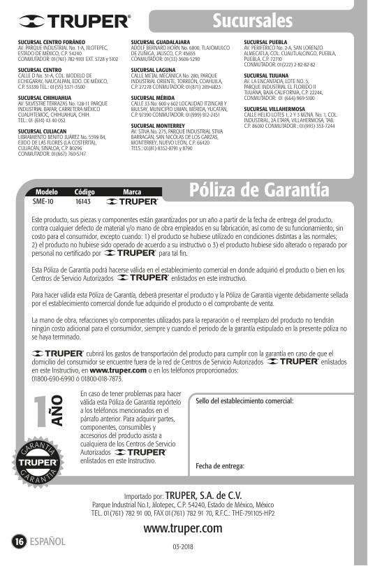
Póliza de GarantíaModelo Código MarcaSME-10 16143
1 AÑ
OSUCURSAL CENTRO FORÁNEOAV. PARQUE INDUSTRIAL No. 1-A, JILOTEPEC,ESTADO DE MÉXICO, C.P. 54240CONMUTADOR: 01(761) 782-9101 EXT. 5728 y 5102
SUCURSAL CENTROCALLE D No. 31-A, COL. MODELO DE ECHEGARAY, NAUCALPAN, EDO. DE MÉXICO,C.P. 53330 TEL.: 01(55) 5371-3500
SUCURSAL CHIHUAHUAAV. SILVESTRE TERRAZAS No. 128-11 PARQUE INDUSTRIAL BAFAR, CARRETERA MÉXICO CUAUHTEMOC, CHIHUAHUA, CHIH. TEL.: 01 (614) 43 40 052
SUCURSAL CULIACANLIBRAMIENTO BENITO JUÁREZ No. 5599 B4, EJIDO DE LAS FLORES (LA COSTERITA), CULIACÁN, SINALOA, C.P. 80296CONMUTADOR: 01(667) 760-5747
SUCURSAL GUADALAJARAADOLF BERNARD HORN No. 6800, TLAJOMULCO DE ZUÑIGA, JALISCO, C.P. 45655CONMUTADOR: 01(33) 3606-5290
SUCURSAL LAGUNACALLE METAL MECÁNICA No. 280, PARQUE INDUSTRIAL ORIENTE, TORREÓN, COAHUILA,C.P. 27278 CONMUTADOR: 01(871) 209-6823
SUCURSAL MÉRIDACALLE 33 No. 600 y 602 LOCALIDAD ITZINCAB Y MULSAY, MUNICIPIO UMAN, MÉRIDA, YUCATÁN, C.P. 97390 CONMUTADOR: 01(999) 912-2451
SUCURSAL MONTERREYAV. STIVA No. 275, PARQUE INDUSTRIAL STIVA BARRAGÁN, SAN NICÓLAS DE LOS GARZAS, MONTERREY, NUEVO LEÓN, C.P. 66420TELS.: 01(81) 8352-8791 y 8790
SUCURSAL PUEBLAAV. PERIFÉRICO No. 2-A, SAN LORENZO ALMECATLA, COL. CUAUTLALCINGO, PUEBLA,PUEBLA, C.P. 72710CONMUTADOR: 01(222) 2-82-82-82
SUCURSAL TIJUANAAV. LA ENCANTADA, LOTE NO. 5, PARQUE INDUSTRIAL EL FLORIDO II TIJUANA, BAJA CALIFORNIA, C.P. 22244,CONMUTADOR: 01 (664) 969-5100
SUCURSAL VILLAHERMOSACALLE HELIO LOTES 1, 2 Y 3 MZNA. No. 1, COL. INDUSTRIAL, 2A ETAPA, VILLAHERMOSA, TAB.C.P. 86010 CONMUTADOR : 01(993) 353-7244
Importado por: TRUPER, S.A. de C.V.Parque Industrial No.1, Jilotepec, C.P. 54240, Estado de México, MéxicoTEL. 01(761) 782 91 00, FAX 01(761) 782 91 70, R.F.C.: THE-791105-HP2
www.truper.com03-2018
Sello del establecimiento comercial:
Fecha de entrega:
Este producto, sus piezas y componentes están garantizados por un año a partir de la fecha de entrega del producto, contra cualquier defecto de material y/o mano de obra empleados en su fabricación, así como de su funcionamiento, sin costo para el consumidor, excepto cuando: 1) el producto se hubiese utilizado en condiciones distintas a las normales; 2) el producto no hubiese sido operado de acuerdo a su instructivo o 3) el producto hubiese sido alterado o reparado por personal no certificado por para tal fin.
Esta Póliza de Garantía podrá hacerse válida en el establecimiento comercial en donde adquirió el producto o bien en los Centros de Servicio Autorizados enlistados en este instructivo.
Para hacer válida esta Póliza de Garantía, deberá presentar el producto y la Póliza de Garantía vigente debidamente sellada por el establecimiento comercial donde fue adquirido el producto o el comprobante de venta.
La mano de obra, refacciones y/o componentes utilizados para la reparación o el reemplazo del producto no tendrán ningún costo adicional para el consumidor, siempre y cuando el periodo de la garantía estipulado en la presente póliza no se haya terminado.
cubrirá los gastos de transportación del producto para cumplir con la garantía en caso de que el domicilio del consumidor se encuentre fuera de la red de Centros de Servicio Autorizados enlistados en este Instructivo, en www.truper.com o en los teléfonos proporcionados:01800-690-6990 ó 01800-018-7873.
En caso de tener problemas para hacer válida esta Póliza de Garantía repórtelo a los teléfonos mencionados en el párrafo anterior. Para adquirir partes, componentes, consumibles y accesorios del producto asista a cualquiera de los Centros de Servicio Autorizados enlistados en este Instructivo.
ESPAÑOL
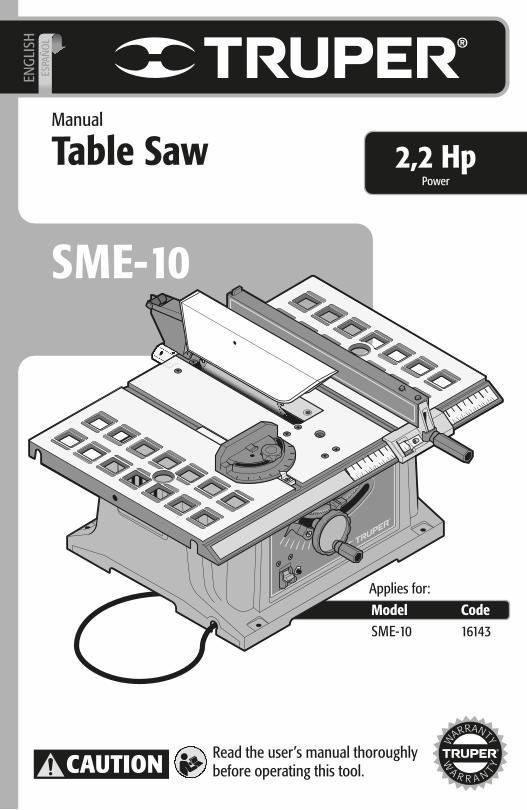
Manual
Table Saw
SME-10
Model CodeSME-10
Applies for:
16143
Power2,2 Hp
ENG
LISH
ESPA
ÑO
L
Read the user’s manual thoroughlybefore operating this tool.CAUTION
2
Technical Specifications
Power Requirements
General Safety Warnings for Power Tools
Safety Warnings for Power Saws
Parts
Mounting
Adjustments
Start Up
Operation
Maintenance
Troubleshooting
Template to Make Tools toPush the Work Piece
Authorized Service Centers
Branches
Warranty Policy
3
3
4
5
6
6
8
10
10
12
13
14
15
16
16
SME-10
ENGLISH
Contents
CAUTION
Keep this manual for future references.
The illustrations in this manual are for reference only. They might be different from the real tool.
To gain the best performance of the tool, prolong the duty life,
make the Warranty valid if necessary, and to avoid hazards of fatal injuries please read and understand this Manual before
using the tool.
SME-10
Technical specifications
Power Requirements
16143
Tungsten Carbide 10” and 36 teeth
Class 0
50 Hz / 60 Hz
Table Saw
50 min work per 20 min rest. Daily Maximum 6 hours
4800 RPM
13 A
2,2 HP
CodeDescription
25-3/4” x 16”Work TableDisc
VoltageFrequency
CurrentPowerSpeed
Work Cycle16 AWG x 2C with 167°F Insulation Power Conductors
Insulation Power cord grips used in this product: Type “Y”.
Build quality: Main InsulationThermal insulation on motor winding: Class B
127 V
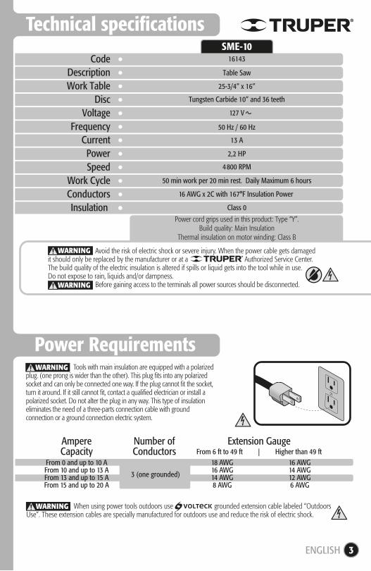
When using power tools outdoors use grounded extension cable labeled “Outdoors Use”. These extension cables are specially manufactured for outdoors use and reduce the risk of electric shock.
WARNING
3
Tools with main insulation are equipped with a polarized plug. (one prong is wider than the other). This plug fits into any polarized socket and can only be connected one way. If the plug cannot fit the socket, turn it around. If it still cannot fit, contact a qualified electrician or install a polarized socket. Do not alter the plug in any way. This type of insulation eliminates the need of a three-parts connection cable with ground connection or a ground connection electric system.
WARNING
ENGLISH
WARNING
WARNING Avoid the risk of electric shock or severe injury. When the power cable gets damaged it should only be replaced by the manufacturer or at a Authorized Service Center.The build quality of the electric insulation is altered if spills or liquid gets into the tool while in use.Do not expose to rain, liquids and/or dampness.
Before gaining access to the terminals all power sources should be disconnected.
From 0 and up to 10 AFrom 10 and up to 13 AFrom 13 and up to 15 AFrom 15 and up to 20 A
18 AWG16 AWG14 AWG8 AWG
16 AWG14 AWG12 AWG6 AWG
3 (one grounded)
From 6 ft to 49 ft | Higher than 49 ftAmpereCapacity
Number ofConductors
Extension Gauge
4 ENGLISH
General Power ToolsSafety Warnings
Work areaKeep your work area clean, and well lit.Cluttered and dark areas may cause accidents.
Never use the tool in explosive atmospheres, such as in the presence of flammable liquids, gases or dust.Sparks generated by power tools may ignite the flammable material.
Keep children and bystanders at a safe distance while operating the tool.Distractions may cause loosing control.
Electrical SafetyThe tool plug must match the power outlet. Never modifythe plug in any way. Do not use any adapter plugs with grounded power tools.Modified plugs and different power outlets increase the risk of electric shock.
Avoid body contact with grounded surfaces, such as pipes, radiators, electric ranges and refrigerators.The risk of electric shock increases if your body is grounded.
Do not expose the tool to rain or wet conditions.Water entering into the tool increases the risk of electric shock.
Do not force the cord. Never use the cord to carry, lift or unplug the tool. Keep the cord away from heat, oil, sharp edges or moving parts.Damaged or entangled cords increase the risk of electric shock.
When operating a tool outdoors, use an extension cord suitable for outdoor use.Using an adequate outdoor extension cord reduces the risk of electric shock.
If operating the tool in a damp location cannot be avoided, use a ground fault circuit interrupter (GFCI) protected supply.Using a GFCI reduces the risk of electric shock.
Personal safetyStay alert, watch what you are doing and use common sense when operating a tool. Do not use a power tool while you are tired or under the influence of drugs, alcohol or medication.A moment of distraction while operating the tool may result in personal injury.
Use personal protective equipment. Always wear eye protection.Protective equipment such as safety glasses, anti-dust mask, non-skid shoes, hard hats and hearing protection used in the right conditions significantly reduce personal injury.
Prevent unintentional starting up. Ensure the switch is in the “OFF” position before connecting into the power source and / or battery as well as when carrying the tool.Transporting power tools with the finger on the switch or connecting power tools with the switch in the “ON” position may cause accidents.
Remove any wrench or vice before turning the power tool on.Wrenches or vices left attached to rotating parts of the tool may result in personal injury.
Do not overreach. Keep proper footing and balance at all times.This enables a better control on the tool during unexpected situations.
Dress properly. Do not wear loose clothing or jewelry. Keep hair, clothes and gloves away from the moving parts.Loose clothes or long hair may get caught in moving parts.
If you have dust extraction and recollection devices connected onto the tool, inspect their connections and use them correctly.Using these devices reduce dust-related risks.
Power Tools Use and Care Do not force the tool. Use the adequate tool for your application.The correct tool delivers a better and safer job at the rate for which it was designed.
Do not use the tool if the switch is not working properly.Any power tool that cannot be turned ON or OFF is dangerous and should be repaired before operating.
Disconnect the tool from the power source and / or battery before making any adjustments, changing accessories or storing.These measures reduce the risk of accidentally starting the tool.
Store tools out of the reach of children. Do not allow persons that are not familiar with the tool or its instructions tooperate the tool.Power tools are dangerous in the hands of untrained users.
Service the tool. Check the mobile parts are not misaligned or stuck. There should not be broken parts or other conditions that may affect its operation. Repair any damage before using the tool.Most accidents are caused due to poor maintenance to the tools.
Keep the cutting accessories sharp and clean.Cutting accessories in good working conditions are less likely to bind and are easier to control.
Use the tool, components and accessories in accordance with these instructions and the projected way to use it for the type of tool when in adequate working conditions.Using the tool for applications different from those it was designed for, could result in a hazardous situation.
ServiceRepair the tool in a Authorized Service Center using only identical spare parts.This will ensure that the safety of the power tool is maintained.
Children or people with reduced physical, sensory or mental capabilities shall not operate the tool, neither inexperienced people or without knowledge in the use of the tool, unless supervised by a person responsible of their safety or if receiving previous instructions about the tool operation.Children shall be kept under supervision to double-check they will not playwith the tool. Tight supervision shall be used with children or disabledpersons to prevent from using or being close to any household tool.
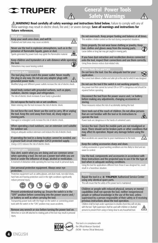
WARNING! Read carefully all safety warnings and instructions listed below. Failure to comply with any of these warnings may result in electric shock, fire and / or severe damage. Save all warnings and instructions for future references.
This tool is in compliance withthe Official Mexican Standard(NOM - Norma Oficial Mexicana).
5
• Remove the machine packing materials and fix it to its base before operating. • Keep a 12” free space around the machine to gain working space. If working with large materials, there shall be enough free space in front and rear of the machine to be able to introduce and remove the material with ease.
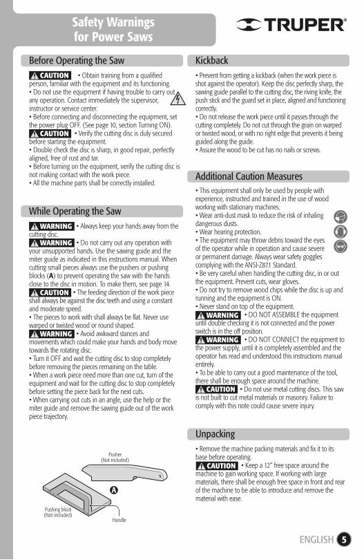
• Always keep your hands away from the cutting disc. • Do not carry out any operation with your unsupported hands. Use the sawing guide and the miter guide as indicated in this instructions manual. When cutting small pieces always use the pushers or pushing blocks (A) to prevent operating the saw with the hands close to the disc in motion. To make them, see page 14. • The feeding direction of the work piece shall always be against the disc teeth and using a constant and moderate speed.• The pieces to work with shall always be flat. Never use warped or twisted wood or round shaped. • Avoid awkward stances and movements which could make your hands and body move towards the rotating disc.• Turn it OFF and wait the cutting disc to stop completely before removing the pieces remaining on the table.• When a work piece need more than one cut, turn of the equipment and wait for the cutting disc to stop completely before setting the piece back for the next cuts.• When carrying out cuts in an angle, use the help or the miter guide and remove the sawing guide out of the work piece trajectory.
• Obtain training from a qualified person, familiar with the equipment and its functioning.• Do not use the equipment if having trouble to carry out any operation. Contact immediately the supervisor, instructor or service center.• Before connecting and disconnecting the equipment, set the power plug OFF. (See page 10, section Turning ON). • Verify the cutting disc is duly secured before starting the equipment.• Double check the disc is sharp, in good repair, perfectly aligned, free of rust and tar.• Before turning on the equipment, verify the cutting disc is not making contact with the work piece.• All the machine parts shall be correctly installed.
Before Operating the Saw
While Operating the Saw
• Prevent from getting a kickback (when the work piece is shot against the operator). Keep the disc perfectly sharp, the sawing guide parallel to the cutting disc, the riving knife, the push stick and the guard set in place, aligned and functioning correctly.• Do not release the work piece until it passes through the cutting completely. Do not cut through the grain on warped or twisted wood, or with no right edge that prevents it being guided along the guide.• Assure the wood to be cut has no nails or screws.
Kickback
Additional Caution Measures
Unpacking
A
Pusher(Not included)
Handle
Pushing block(Not included)
CAUTION
CAUTION
CAUTION
WARNING
WARNING
WARNING
CAUTION
• This equipment shall only be used by people with experience, instructed and trained in the use of wood working with stationary machines.• Wear anti-dust mask to reduce the risk of inhaling dangerous dusts.• Wear hearing protection.• The equipment may throw debris toward the eyesof the operator while in operation and cause severeor permanent damage. Always wear safety goggles complying with the ANSI-Z87.1 Standard.• Be very careful when handling the cutting disc, in or out the equipment. Prevent cuts, wear gloves.• Do not try to remove wood chips while the disc is up and running and the equipment is ON.• Never stand on top of the equipment. • DO NOT ASSEMBLE the equipment until double checking it is not connected and the power switch is in the off position. • DO NOT CONNECT the equipment to the power supply, until it is completely assembled and the operator has read and understood this instructions manual entirely.• To be able to carry out a good maintenance of the tool, there shall be enough space around the machine. • Do not use metal cutting discs. This saw is not built to cut metal materials or masonry. Failure to comply with this note could cause severe injury.
WARNING
WARNING
CAUTION
ENGLISH
Safety Warningsfor Power Saws
Parts
Mounting
RetractileGuard
Spacer
Cabinet
PowerCable
CuttingDisc
WorkTable
Switch OverloadProtector Switch
MiterGuide
Adjusting Wrenches
SawingGuide
CutScale
Work Bench,Pedestal orCabinet
SieveMesh
Miter GuideSlots
6
• The saw shall be fixed to a stable, solid, fixed and leveled work bench before starting it.• Set the saw onto the work bench in the position most adequate to work. Consider at least 12” free space from the saw work bench to any wall or obstacle. If working with large work pieces, you need even more free space to prevent the work pieces to bump and make you lose control over the tool.• Use a pencil to mark the four mounting orifices on the work bench surface.• Remove the saw from the work bench and make four 5/16” diameter perforations in the penciled marks.• In the center of the perforations, mark, cut and remove a 12” square to allow the exit of the sawdust into the saw cabinet as well as allowing the proper ventilation to the motor.• To prevent touching the disc underneath the work bench, cover the square orifice with sieve mesh. Do not use mosquito net because it stops sawdust to exit.• Fix the saw onto the bench with bolts 1/4” diameter, nuts and flat washers (not included). Tighten gradually each bolt, one by one to perfectly fix the cabinet base.
Height Controland Disc Angle
Flywheel
Cutting AngleBlocking Knob
Scale and Pointerof the Cutting Angle
Sawing GuideControl
MountingOrifices
7
Mounting
Sawing Guide
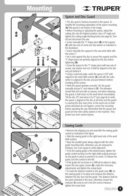
• The disc guard is factory-mounted in the spacer. To simplify the mounting explanation of the spacer mounting (A) lthe guard is not shown in the image.• Before mounting or adjusting the spacer, adjust the cutting disc into the highest position, into a 0° angle and tighten the cutting angle blocking knob (see page 8). Turn off and disconnect the saw.• Screw manually the “L” shape piece (B) to the support (C) with two sets of screw and star washer as indicated in the illustration.• Screw manually the support to the saw work table with the screw 2”.• Set a ruler against the disc to assure the support and the “L” shape piece are perfectly aligned to the disc before tightening (D).• Screw the spacer to the “L” shape piece with two sets of screws, star washer and nut. It shall be aligned to the disc and just behind it. • Using a universal angle, verify the spacer is 90° with regards to the work table surface (E) and with the ruler, verify it is aligned to the disc and just behind it before screwing all the screws.• Verify the guard operates correctly. Lift, the guard manually around 4” and release it (F). The elevation should feel soft and with no pauses, and when releasing the guard, it shall return to the work bench immediately. Tilt the disc 45° and return it to 0° (see page 8) to verify the spacer is aligned to the disc at all times and the guard is covering the disc every time. In the event one or both points described do not happen, correct the mounting before operating the saw. Remember that the spacer and guard are the main safety systems in the machine. They protect you from severe injuries.
• Remove the shipping nut and assemble the sawing guide control as indicated in the figure.• Slide the sawing guide in the right-hand side of the work table surface.• Keep the parallel guide always aligned with the miter guide mounting slots, otherwise, you are exposed to kickback. Use a set square to verify alignment.• To fix the sawing guide in the desired place, tighten the guide control turning it to the right while putting pressure on the guide in place to prevent it to move. To release the guide, turn the control to the left.• If the guide sits too loose or is difficult to adjust or align, loosen the two upper screws (G), make the necessary adjustments and tighten the screws back.• To mark the distance marked in the guide visor (H), fix the sawing guide in its place and measure the distance between the disc face and the guide. This distance shall be the same indicated in the visor, otherwise, loosen the indicator (I) screw to set it into the correct measure. tighten the screw back.
Spacer and Disc Guard
C
G
H
I
D E
F
B
A
ENGLISH
8
Mounting
Adjustments
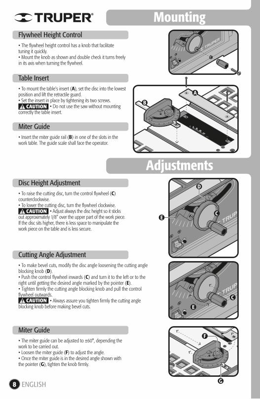
• The flywheel height control has a knob that facilitate tuning it quickly.• Mount the knob as shown and double check it turns freely in its axis when turning the flywheel.
Flywheel Height Control
• To mount the table’s insert (A), set the disc into the lowest position and lift the retractile guard.• Set the insert in place by tightening its two screws. • Do not use the saw without mounting correctly the table insert.
Table Insert
• Insert the miter guide rail (B) in one of the slots in the work table. The guide scale shall face the operator.
Miter Guide
• The miter guide can be adjusted to ±60°, depending the work to be carried out.• Loosen the miter guide (F) to adjust the angle.• Once the miter guide is in the desired angle shown with the pointer (G), tighten the knob firmly.
Miter Guide
• To raise the cutting disc, turn the control flywheel (C) counterclockwise.• To lower the cutting disc, turn the flywheel clockwise. • Adjust always the disc height so it sticks out approximately 1/8” over the upper part of the work piece. If the disc sits higher, there is less space to manipulate the work piece on the table and is less secure.
Disc Height Adjustment
• To make bevel cuts, modify the disc angle loosening the cutting angle blocking knob (D).• Push the control flywheel inwards (C) and turn it to the left or to the right until getting the desired angle marked by the pointer (E).• Tighten firmly the cutting angle blocking knob and pull the control flywheel outwards. • Always assure you tighten firmly the cutting angle blocking knob before making bevel cuts.
Cutting Angle Adjustment
E
F
G
D
C
C
B
A
CAUTION
CAUTION
CAUTIONE
ENGLISH
9
Adjustments
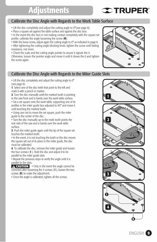
• Lift the disc completely and adjust the cutting angle to 0°(see page 8).• Place a square set against the table surface and against the disc face.• In the event the disc face in not making contact completely with the square set profile, calibrate the angle loosening the screw (H).• With the loose screw, adjust again the cutting angle to 0° as indicated in page 8.• After tightening the cutting angle blocking knob, tighten the screw until feeling resistance, not more.• Check the scale and the cutting angle pointer to assure it signals the 0. Otherwise, loosen the pointer angle and move it until it shows the 0 and tighten the screw again.
Calibrate the Disc Angle with Regards to the Work Table Surface
• Lift the disc completely and adjust the cutting angle to 0° (see page 8).1. Select one of the disc teeth that point to the left and mark it with a pencil or marker.2. Turn the disc manually until the marked tooth is pointing to the saw front and is barely over the work table surface.• Set a set square onto the work table, supporting one of its profiles in the miter guide face adjusted to 90° and move it until touching the marked tooth.• Using care not to move the set square, push the miter guide to the center of the disc.• Turn the disc manually up to the mark tooth points the rear side of the saw and is barely over the work table surface.3. Push the miter guide again until the tip of the square set touches the marked tooth.• In the event, it is not touching the tooth or the disc moves the square set out of its place in the miter guide, the disc must be calibrated.4. To calibrate the disc, remove the miter guide and loosen the four screws ( I ). Hold the disc and adjust it to be parallel to the miter guide slots.• Repeat the previous steps to verify the angle until it is parallel to the slots. • Only in the event the angle cannot be corrected after loosening the 4 screws ( I ), loosen the two screws (K) to make the adjustment.• Once the angle is calibrated, tighten all the screws.
Calibrate the Disc Angle with Regards to the Miter Guide Slots
H
I
K
1
2
3
4
CAUTION
ENGLISH
A
D
Start Up
Operation
10
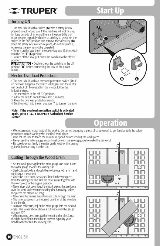
• The saw is built with a switch (A) with a safety key to prevent unauthorized use. If the machine will not be used for long periods of time and there is the possibility that other people, especially children, could try to use it, set the switch in the “O” position and remove the safety key (B). Keep the safety key in a secure place, do not misplace it, otherwise the saw cannot be operated.• To turn on the saw, insert the safety key and lift the switch into the ON “I” (C) position. • To turn off the saw, put down the switch into the off “O” position. • Double check the switch is in the off position “O” before connecting the saw to the power mains.
Turning ON
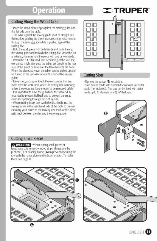
• Set the work piece against the miter gauge and push it with the miter gauge towards the cutting disc.• Start cutting slowly and push the work piece with a firm and continuous movement.• Once the cut is done, separate a little bit the work piece from the cutting disc and turn the miter gauge together with the work piece to the original position.• Never stop, pick up or touch the work pieces that are loose over the work table when the cutting disc is moving, unless the pieces are at least 12” long.• Never use the sawing guide to make cuts through the grain.• The miter gauge can be mounted on either of the two slots in the bench.• To make miter cuts, adjust the miter gauge into the desired angle. The image above shows a cut made with the gauge sitting at 45°.• When making bevel cuts (with the cutting disc tilted), use the right-hand slot in the table to prevent exposing your hands to the teeth in the moving disc.
Cutting Through the Wood Grain
• The saw is built with an overload protection switch (D). If an overload happens, the switch will trigger and the motor will be shut off. To reestablish the motor, follow the following steps:1. Set the switch in the off “O” position. 2. Allow the saw to cool down al leas 5 minutes.3. Press the overload protection switch.4. Set the switch into the on position “I” to turn on the saw.
Electric Overload Protection
• We recommend make tests of the work to be carried out using a piece of scrap wood, to get familiar with the safest procedure before starting with the final work piece.• Wait for the disc to reach the maximum speed before feeding the work piece.• Never use the miter gauge in combination with the sawing guide to make the same cut.• Be sure to press firmly the miter guide knob or the sawing guide before carrying out the cut.
WARNING
B C
Note: If the overload protection switch is activated again, go to a Authorized Service Center.
ENGLISH
E
F
Operation
11
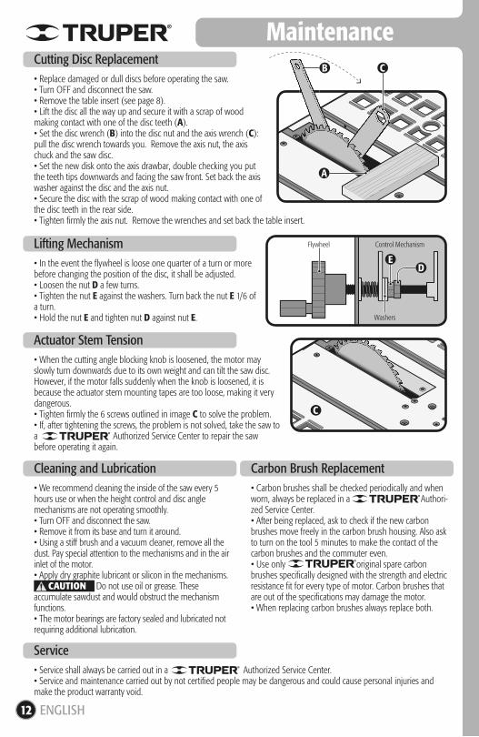
• Place the wood piece edge against the sawing guide and the flat side onto the table.• The edge against the sawing guide shall be straight and flat to allow guiding the piece in a safe and precise manner through the sawing guide while is pushed against the cutting disc.• Hold the work piece with both hands and push it along the sawing guide and towards the cutting disc. Once the cut is initiated, you may hold the piece with one or two hands.• When the cut is finished, and depending of the size, the work piece might stay onto the table, get caught in the rear side of the guard or slide over the table towards the floor.When the pieces stay over the table, can be picked up and be turned to the opposite side of the disc of the sawing guide.• Never stop, pick up or touch the work pieces that are loose over the work table when the cutting disc is moving, unless the pieces are long enough to be removed safely.• It is important to have the guard and the spacer duly mounted to prevent kickback and to prevent the cut to close after passing through the cutting disc.• When making bevel cuts (with the disc tilted), use the sawing guide in the right-hand side of the table to prevent exposing your hands to the moving disc teeth or the piece gets stuck between the disc and the sawing guide.
Cutting Along the Wood Grain
• When cutting small pieces or lengthwise cuts in narrow wood strips, always use the pushers (F) or pushing blocks (G) to prevent operating the saw with the hands close to the disc in motion. To make them, see page 14.
Cutting Small Pieces
• Remove the spacer (E) to cut slots.• Slots can be made with normal discs or with slot cutter heads (not included). The saw can be fitted with cutter heads up to 6” diameter and 9/16” thickness.
Cutting Slots
G
WARNING
ENGLISH
• Service shall always be carried out in a Authorized Service Center.• Service and maintenance carried out by not certified people may be dangerous and could cause personal injuries and make the product warranty void.
• Carbon brushes shall be checked periodically and when worn, always be replaced in a Authori-zed Service Center.• After being replaced, ask to check if the new carbon brushes move freely in the carbon brush housing. Also ask to turn on the tool 5 minutes to make the contact of the carbon brushes and the commuter even.• Use only original spare carbon brushes specifically designed with the strength and electric resistance fit for every type of motor. Carbon brushes that are out of the specifications may damage the motor.• When replacing carbon brushes always replace both.
• We recommend cleaning the inside of the saw every 5 hours use or when the height control and disc angle mechanisms are not operating smoothly.• Turn OFF and disconnect the saw.• Remove it from its base and turn it around.• Using a stiff brush and a vacuum cleaner, remove all the dust. Pay special attention to the mechanisms and in the air inlet of the motor.• Apply dry graphite lubricant or silicon in the mechanisms. Do not use oil or grease. These accumulate sawdust and would obstruct the mechanism functions.• The motor bearings are factory sealed and lubricated not requiring additional lubrication.
Flywheel
Washers
Control Mechanism
B C
A
D
C
E
Maintenance
12
• Replace damaged or dull discs before operating the saw.• Turn OFF and disconnect the saw.• Remove the table insert (see page 8).• Lift the disc all the way up and secure it with a scrap of wood making contact with one of the disc teeth (A).• Set the disc wrench (B) into the disc nut and the axis wrench (C): pull the disc wrench towards you. Remove the axis nut, the axis chuck and the saw disc.• Set the new disk onto the axis drawbar, double checking you put the teeth tips downwards and facing the saw front. Set back the axis washer against the disc and the axis nut.• Secure the disc with the scrap of wood making contact with one of the disc teeth in the rear side.• Tighten firmly the axis nut. Remove the wrenches and set back the table insert.
Cutting Disc Replacement
Cleaning and Lubrication
Service
• In the event the flywheel is loose one quarter of a turn or more before changing the position of the disc, it shall be adjusted.• Loosen the nut D a few turns.• Tighten the nut E against the washers. Turn back the nut E 1/6 of a turn.• Hold the nut E and tighten nut D against nut E.
Lifting Mechanism
• When the cutting angle blocking knob is loosened, the motor may slowly turn downwards due to its own weight and can tilt the saw disc. However, if the motor falls suddenly when the knob is loosened, it is because the actuator stem mounting tapes are too loose, making it very dangerous.• Tighten firmly the 6 screws outlined in image C to solve the problem.• If, after tightening the screws, the problem is not solved, take the saw to a Authorized Service Center to repair the saw before operating it again.
Actuator Stem Tension
Carbon Brush Replacement
CAUTION
ENGLISH
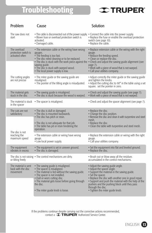
13
Troubleshooting
The saw does not start
The overload protection switch is activated often
The cutting angles are not precise
The material gets stuck in the disc
The material is stuck in the spacer
The cuts are not satisfactory
The disc is not reaching the maximum speed
The equipment vibrates in excess
The disc is not raising or tilting freely
The material is sent back with the disc movement
• The cable is disconnected out of the power supply.• Blown fuse or overload protection switch is activated.• Damaged cable.
• The extension cable or the wiring have wrong gauges.• The feeding is too fast.• The disc need cleaning or to be replaced.• The disc is stuck with the work piece against the sawing guide.• The disc is stuck with warped wood.• The local power supply is low.
• The miter guide or the sawing guide are misaligned.• The pointer of the tilting angle is misadjusted.
• The sawing guide is misaligned.• The disc is stuck because the wood is warped.
• The spacer is misaligned.
• The disc is dull or damaged.• The disc is mounted backwards.• The disc has pitch or resin.
• The disc is not adequate for that job.• The table has pit or resin hindering the operation.
• The extension cable or wiring have wrong gauge.• Low local power supply.
• The equipment is set in uneven ground.• The disc is damaged.
• The control mechanisms are dirty.
• The sawing guide is misaligned.• The spacer is misaligned.• The material is fed without the sawing guide.• The spacer is not installed.• Dull or worn cutting disc.• The material gets loose before going through the disc.
• The miter guide knob is loose.
• Connect the cable into the power supply.• Replace the fuse or enable the overload protection switch (see page 10).• Replace the cable.
• Replace extension cable or the wiring with the right gauge.• Reduce the feeding speed.• Clean or replace the disc.• Check and adjust the sawing guide alignment (see page 7).• Work with a piece of wood that is not warped.• Call your utilities company.
• Adjust correctly the miter guide or the sawing guide and tighten the knobs.• Adjust the cutting disc to 90° in the table using a set square. set the pointer in zero.
• Check and adjust the sawing guide (see page 7).• Work with a piece of wood that is not warped.
• Check and adjust the spacer alignment (see page 7).
• Replace the disc.• Change the disc position.• Remove the disc and clean it with turpentine and steel mesh.• Replace the disc.• Clean the table with turpentine and steel mesh.
• Replace the extension cable or wiring with the right gauge.• Call your utilities company.
• Set the equipment into flat and leveled ground.• Replace the disc.
• Brush out or blow away all the residues accumulated in the control mechanisms.
• Adjust the sawing guide angle.• Adjust the spacer angle.• Support the material in the sawing guide.• Set the spacer.• Replace the disc with another one in good repair.• Support and push the material with the help of the pushers and the pushing block until they pass through the disc.• Tighten the miter guide knob.
Problem Cause Solution
ENGLISH
If the problems continue despite carrying out the corrective actions recommended,contact a Authorized Service Center.

Notch and handlein angle to prevent
the hand slidingtowards thecutting disc
OptionalOrifice
14
Template to Make Toolsto Push the Work Piece
1/2”
• To make the pusher (A) use 1/2”, 3/4” wood or a lower thickness of the material to be cut with a table saw.• To make the handle of the pushing block (C) use 1/2”, and for the block, use wood not smaller than 1/2”. • Use hard wood or plywood to make these tools.• Each square in the templates equals 1/2”.
CAUTION
The cut ( ) shall be made to the
thickness of the wood to push (B).
B
A
C
Pusher
Handle
ENGLISH
Authorized Service Centers
15
671615 SUPER TOOLSZARAGOZA NO. 1205, COL. EL SOL, AGUASCALIENTES, AGS. TEL.: 01(449) 996-5978
670796 CONTRURENTASPROL. I. ZARAGOZA Y MÁRQUEZ DE LEÓN,COL. 5 DE FEBRERO, SAN JOSÉ DEL CABO, BCSTEL.: 01(624) 142-4595
670032 PROVINDAV. COLEGIO MILITAR No. 4307 A, COL. NOMBRE DE DIOS C.P. 31100, CHIHUAHUA, CHIH. TEL.: 01(614) 424-4000
671530 FERRETERÍA AMAYA S.A. DE C.V.AV. ORTIZ MENA No. 81, COL. CENTRO C.P. 33800 PARRAL, CHIH. TEL.: 01(627) 522-2600
670712 INDUSTRIAL FERRETERA DE MONCLOVA, S.A. DE C.V. BLVD. HAROLD R. PAPE No. 1000, COL. CENTRO C.P. 25700 MONCLOVA, COAH.TEL.: 01(866) 632-0174 FAX: 01(866) 633-0719
671742 SURTIDORA DE FERRETERÍA AV. ANTONIO LEAÑO ÁLVAREZ No. 527 COL. PONCIANO ARRIAGA. TECOMÁN, TEL.: 01(313) 324-2000 y 7666 FAX: 325-2700
671770 TORNILLOS Y HERRAMIENTAS PINEDA 17 PONIENTE No. 20-A, COL. CENTRO TAPACHULA, CHIAPASTEL.: 01(962) 626-2807
671709 FERRETERA MANDIOLA, S.A. DE C.V. 5a NORTE PONIENTE No. 1615-B, COL. MOCTEZUMA,C.P. 29000, TUXTLA GUTIÉRREZ, TEL.: 01(961) 602-1544
671747 CENTRO DE SERVICIO DEL SURESTE LIBRAMIENTO SUR ORIENTE S/N km 6.5COL. TRABAJADORES, TUXTLA GUTIÉRREZ, CHIAPASTEL.: 01(961) 223-2350
670515 FERRETERÍA CASUARAMÓN CORONA No. 72, COL. BARRIO SANTA LUCÍA C.P. 29250, SAN CRISTOBAL DE LAS CASAS, CHIS.TEL.: 01(967) 678-6283
671601 MATERIALES DE CONSTRUCCIÓN DE LOS ALTOS, S.A. DE C.V. FRANCISCO I. MADERO No.5, COL. CENTRO, C.P. 29200, SAN CRISTOBAL DE LAS CASAS, CHIS.
671730 MATERIALES Y ACEROS BALAM S.A. PERIFERICO NORTE-PONIENTE No. 50 COL. BISMAR, SN. CRISTOBAL DE LAS CASAS TEL.: 01 (967) 678-6162 y 7422
670781 PREFABRICADOS DE PALENQUE, S.A. DE C.V. km 1 CARRETERA PALENQUE - PAKAL-NÁ S/N ENTRADA LIENZO CHARRO C.P. 22960, PALENQUE, CHIS. TEL.: 01 (916) 345-1523 | 345-1533
671829 EL FUERTE DE LAS HERRAMIENTAS S.A. DE C.V. PONIENTE 140 No.618 LOCAL B, COL. INDUSTRIAL VALLEJO, AZCAPOTZALCO, C.P. 02300 TELS.: 01(55) 5587-7959 y 7731
670995 EL MONSTRUO DE CORREGIDORA S.A. DE C.V. CORREGIDORA No.22, COL. CENTRO C.P. 06060 CIUDAD DE MÉXICO TEL.: 01(55) 5522-4861 | 71 y01(55) 5522-5031, FAX: 01(55) 5522-5021
671370 ADMINISTRADORA FERRETERA, S.A. DE C.V. CORREGIDORA No. 76-A, COL. CENTRO C.P. 06060 CIUDAD DE MÉXICO TEL.: 01 (55) 5522-9976FAX: 01(55) 5522-9966
671131 CERRADA PINO SUAREZ No. 24, COL. ZONA ESCOLAR C.P. 07230, GUSTAVO A. MADERO, CIUDAD DE MÉXICO TEL.: 01(55) 2207-0882
671137 INGENIERÍA SUMINISTROS Y SERVICIOS INDUSTRIALES CALZADA DE GUADALUPE No.525-A, COL. ESTRELLA, C.P. 07810, GUSTAVO A. MADERO, CIUDAD DE MÉXICO TEL. Y FAX: 01(55) 5577-9331 | 5781-7079
670350 TORNILLOS ÁGUILA, S.A. DE C.V.MASURIO No. 200 ESQUINA GALIO, COL. LUIS ECHEVERRIA C.P. 34250, DURANGO, DGO.TEL.: 01(618) 817-1946 | 818-2655
671671ENRIQUE CARROLA ANTUNA NO. 406 COL. CIÉNEGA, DURANGO, DGO. TEL.: 01(618) 825-2710
671600 ABC DE MATERIALES, S.A. DE C.V. VENUSTIANO CARRANZA No. 104 COL. LOS ÁNGELES TOTOLCINGO, ACOLMAN, EDO. DE MÉXICOTEL.: 01(55) 2958-8504
671723 FERRETERA TECAMAC S.A. DE C.V.CARR. MEXICO-PACHUCA km 37.5 TECAMAC, EDO. DE MÉXICO. TEL.: 5934-6396 Y 5934-6271
671765 TLAPALERIA CRUZAV. CUAUHTEMOC No. 3 COL. BO. SAN JOSÉ, TEQUIXQUIAC, TEL.: 591-91-203-44
671025 SERVICIO Y VENTA DE HERRAMIENTAS VGAV. DE LOS MAESTROS No. 14, COL. LEANDRO VALLE C.P.54040, TLANEPANTLA DE BAZ, EDO. DE MÉXICO, TEL.: 01(55) 2628-3120 Y FAX: 01(55) 5398-2104
670050 ABRASIVOS Y SOLDADURAS ESPECIALES DE TOLUCA ISABEL LA CATÓLICA SUR No. 101 ESQ. MIGUEL HIDALGO COL. STA. CLARA C.P. 50090, TOLUCA, EDO. DE MÉXICO, TEL.: 01(722) 773-1117 | 773-1116 | 214-9458, FAX: 01(722) 215-2145
670514AV. TEXCOCO No. 354, COL. METROPOLITANA 2A SECCIÓN C.P. 57740, CD. NEZAHUALCOYOTL, EDO. DE MÉXICO, TEL.: 01(55) 5792-4458
670150 COMPAÑÍA FERRETERA NUEVO MUNDOS.A. DE C.V. AV. MÉXICO - JAPÓN No. 225, CD. INDUSTRIAL C.P. 38010, CELAYA, GTO. TEL. Y FAX: 01(461) 617-7578 | 617-7579 | 617-7580 | 617-7588
670261 PROVEEDORES DE HERRAMIENTASSINALOA No. 39 COL. MIGUEL HIDALGOIRAPUATO, GTO. TELS.: 01(462) 626-3813, 124-8806 FAX: 01 (462) 623-0523
671492 HERRAMIENTAS Y SERVICIOS DE LEÓN S. DE R.L. DE C.V. LÓPEZ MATEOS ORIENTE No. 230, COL. CENTRO CP. 37000 LEÓN, GTO. TEL./FAX 01(477) 714-6514
671290 EL GRINGO LIBRAMIENTO SUR No. 609, COL. DEL SOL C.P. 37900 SAN LUIS DE LA PAZ, GTO. TEL. Y FAX: 01 (468) 688-4886
670926 DISTRIBUIDORA RAGASA, S.A. DE C.V.AV. LÁZARO CÁRDENAS No. 908, COL. CENTRO C.P. 40660 CD. ALTAMIRANO, GRO. TEL.: 01(767) 672-0843
671637LAS PALMERAS No. 48 COL. CENTRO, COYUCA DE BENÍTEZ, GRO. TEL.: 01(781) 452-0815
671677MARIANO ABASOLO S/N COL. OMETEPEC CENTRO, OMETEPEC, GRO.TEL.: 01(741) 412-1339
670915 MUNDO TOOL MÉXICO, S.A. DE C.V. ALLENDE No. 320, COL. CENTRO C.P. 42000, PACHUCA, HGO. TEL. Y FAX: 01(771) 715-0048
670640 SAN ANTONIO MATERIALES PARA CONSTRUCCIÓN CARR. MEXICO-PACHUCA km 81.5 COL. SAN ANTONIO EL DESMONTE, TEL.: 01(771) 711- 0732
670655 FERREPRECIOS, S.A. DE C.V. LIBERTAD ORIENTE No. 304 LOCAL 30, INTERIOR DE PASAJE ROBLEDO, COL. CENTRO, TULANCINGO, TEL. 01(775) 753-6615 y 16
670855 MAGNOCENTRO FERRETERO, S.A. DE C.V.AV. LA PAZ No.1180, COL. CENTRO, GUADALAJARA, JAL. TEL.: 01(33) 3658-1867 y 59FAX: 01(33) 3658-1870
670770 ACEROS Y MATERIALES DIAZ S.A. DE C.V. AV. FRANCISCO ZARCO No. 755, COL. FLORIDA C.P. 47800, OCOTLAN, JAL. TEL.: 01(392) 922-4740 | 922-0177
671737 EQUIPOS Y HERRAMIENTAS PROFESIONALES JOSÉ MANUEL DE HERRERA No. 149, COL. CENTRO, APATZINGÁN, TEL. 01(453) 534-2204
671766 SERVICIOS Y HERRAMIENTAS DEL SURAV. 22 DE OCTUBRE No. 303 COL. MIGUEL HIDALGO, APATZINGÁN, TEL. 01(453) 534-2033
671830 MOTOSIERRAS Y SERVICIOS DE MORELIA MORELOS NORTE No. 821 COL. CENTRO, MORELIA, C.P. 58000 TEL.: 01(443) 317-9482
670336 FERREMAQUINARIA INDUSTRIAL S.A. DE C.V. AV. LÁZARO CÁRDENAS No. 241, COL. CENTRO C.P. 60950, CD. LÁZARO CÁRDENAS, MICH.TEL.: 01(753) 532-0738 | 532-4396 | 532-2541 FAX: 01(753) 532-3366
670872 MATERIALES GARCÍA Y BARRAGÁN S.A. DE C,V. IGNACIO ZARAGOZA No. 187 B, COL. CENTRO,C.P. 61650, TACÁMBARO, MICH. TEL.: 01(459) 596-0190, FAX: 01(459) 596-0700
671130 HERRAMIENTAS Y SERVICIOS FORESTALES DE ZAMORA AV. JUÁREZ No. 213 OTE. ENTRE 5 DE MAYO Y AQUILES SERDAN, COL. CENTRO C.P. 59600, ZAMORA, MICH. TEL.: 01(351) 517-8420
670805 LA NUEVA FERRETERÍA TRUPERGENERAL PUEBLITA No. 356, COL. CENTRO C.P. 58600, ZACAPU, MICH. TEL.: 01(436) 363-3351
671115 HERRAMIENTAS Y SERVICIOS INDUSTRIALES DE ZITACUARO NETZAHUALCOYOTL NORTE No. 6, COL. MOCTEZUMA C.P. 61505, ZITACUARO, MICH.TEL.: 01(715) 151-3228
671664AVENIDA FRANCISCO VILLA NO. 31 COL. MORELOS, URUAPAN, MICH. TEL.: 01(452) 528-9536
671877 FERREMATERIALES DURAMAX km 100 CARR. MEXICO-ACAPULCO, COL. ALPUYECA, C.P. 62797TEL.: 01(777) 678-9069 TEL. / FAX: 01(777) 678-7956
671625 MARTÍNEZ BARRANCO, S.A. DE C.V. AV. LA PAZ No. 721 COL. CALIFORNIA, OAXACA TEL.: 01(951) 133-1521
671712 MUNDO MAKITA SÍMBOLOS PATRIOS No. 101,COL. ELISEO JIMÉNEZ RUÍZ, OAXACA, OAX
671782 MIFERRECARR. COSTERA DEL PACÍFICO No. 300, COL. LOS MANGALES, PUERTO ESCONDIDO TEL.: 01(954) 582-4218
671794 AGROBOMBAS ROSARIOS S.A. AV. INDEPENDENCIA No. 1323 COL. LA PIRAGUA, TUXTEPEC C.P. 68300 TEL.: 01(287) 875-1363
671420 DISTRIBUIDORA DE HERRAMIENTAS MANUALES ZAVALETA, S.A. DE C.V.RIVERA ATOYAC No. 325, COL. SANTA CRUZ BUENA VISTA, C.P. 72810, SAN ANDRÉS CHOLULA, PUE. TEL. / FAX: 01(222) 249-8592
671211 SERVITECAV. DE LA JUVENTUD No. 1103 ESQ. 7 SUR,COL. NICÓLAS BRAVO C.P. 75790, TEHUACAN, PUE. TEL. / FAX: 01(238) 371-7200
671822 TIENDA FIX TEHUACANAV. SEGUNDA DE MORELOS No. 303, COL. CENTRO, TEHUACÁN, TEL.: 01(238) 384-8640
670402 MOTORES Y HERRAMIENTAS ELÉCTRICAS AV. 6 No. 1004-B ESQ. CALLE 19, COL. LOMAS DE CASA BLANCA C.P. 76080, QUERETARO, QRO.TEL. Y FAX : 01(442) 167-4733
671265 FERRETERA PRADO HERRAMIENTAS S.A. DE C.V. AV. UNIVERSIDAD No. 325-A, COL. GRANJAS MANTHI C.P. 76808, SAN JUAN DEL RIO, QRO.TEL. / FAX : 01(427) 268-4544
670046 CENTRO FERRETERO DE CANCÚNAV. COMACALCO No. 12, COL. SUPERMANZANA 59 C.P. 77515, CANCÚN, Q. ROO.TEL.: 01(998) 886-8777 | 887-6616
671011ÁLVARO OBREGÓN No. 281-283 COL. CENTRO, CHETUMAL, QUINTANA ROO TEL.: 01(983) 833-2358
671732 MULTISIERRAS TALICUMI AVENIDA MIGUEL HIDALGO NO.221 COL. VENUSTIANO CARRANZA, CHETUMAL.
671636 95/24 MÉXICO, S.A. DE C.V. SUC. SLPAV. UNIVERSIDAD No. 1850 COL. EL PASEO, SAN LUIS POTOSÍ C.P. 78320 TEL. / FAX: 01(444) 822-4341
671642JACARANDAS S/N COL. DEL BOSQUE, GUASAVE, SIN. TEL.: 01(687) 871-2636
671045 FERRETERÍA LA ÚNICALÁZARO MERCADO No. 1234 COL. MUNICIPIO LIBRE C.P. 85080 CD. OBREGÓN, SON. TEL. / FAX: 01(644) 412-9836
671610 GRUPO VAQUEIRO FERRETERO, S.A. DE C.V. PERIFÉRICO CARLOS PELLICER CÁMARA No. 2810 COL. MIGUEL HIDALGO, VILLAHERMOSA, C.P. 86250 TEL. / FAX: 01(993) 116-1901 y 41 EXT. 106
671432 MERCADO DE LA SOLDADURA DEL SURESTE, S.A. DE C.V. BLVD. ADOLFO RUÍZ CORTÍNEZ 2001-B,COL. ATASTA, VILLAHERMOSA, C.P. 86100 TEL.: 01(933) 161-4820 | 161-4479
671480 CONSTRURAMA GÁLVEZREVOLUCIÓN No. 1002, COL. BUENA VISTA C.P. 88120 NVO. LAREDO, TAM. TEL. / FAX: 01(867) 710-3100
671755 FERRETERÍA ZANELLAAV. TAMAULIPAS No. 713 COL. REVOLUCIÓN VERDE, TAMPICO, TEL.: 01(833) 306-6537
671684 SERVICIO JUNIORCALLE 2 DE ABRIL PONIENTE No. 506, COL. CENTRO, APIZACO, TEL. 01(241) 112-0996
671435 METALURVE, S.A. DE C.V. CALLE 18 No. 2117, FRACC. LOMAS C.P. 94570 CÓRDOBA, VER. TEL.: 01(271) 714-8584
671635 LA CASA DISTR. TRUPERSUC. AV. YUCATÁN No. 137-A, COL. YUCATÁN C.P. 93600MARTÍNEZ DE LA TORRE, VER. TEL.: 01(232) 373-5420
671478 TALLER ELÉCTRICO MATHEYATENAS No. 71, COL. NUEVA MINA C.P. 96760MINATITLAN, VER. TEL. / FAX : 01(922) 223-5601
671605HUMBOLT SUR No. 49, COL. CENTRO C.P. 91270 PEROTE, VER. TEL.: 01(282) 832-0327 | 825-6408
670397 LA CASA DISTRIBUIDORA TRUPER CALLE URUGUAY No. 713, COL. 27 DE SEPTIEMBRE C.P. 93320, POZA RICA, VER. TEL. / FAX: 01(782) 823-8100 | 826-8484
671535 DISTRIBUIDORA SANVER S.A. DE C.V. CARRETERA NAL. TUXPAN-TAMPICO km 64, COL. LA MORITA, TANTOYUCA, C.P. 92101 TEL.: 01(789) 893-3030
671451 MAYORISTAS JAGUAR S.A. DE C.V. AV. IGNACIO ALLENDE No. 2377 COL. CENTRO, VERACRUZ, TEL.: 01(229) 931-1891
671781 MATERIALES Y ACEROS TUCÁN S.A. DE C.V. PROL. AV. MIGUEL ALEMÁN No. 3800 COL. ARTÍCULO 123, VERACRUZ, TEL.: 01(229) 923-0070
671452 COMERCIALIZADORA FERRESMAR CAYETANO RIVERA No. 47 COL. DEL MAESTRO, VERACRUZ, TEL. 01(229) 922-7948TEL. / FAX: 01(229) 927-1771
AGUASCALIENTES
BAJA CALIFORNIA SUR
CHIHUAHUA
COAHUILA
COLIMA
CHIAPAS
MEXICOCITY
DURANGO
ESTADO DE MÉXICO
GUANAJUATO
GUERRERO
HIDALGO
JALISCO
MICHOACÁN
MORELOS
OAXACA
PUEBLA
QUERÉTARO
QUINTANA ROO
SAN LUIS POTOSÍ
SINALOA
SONORA
TABASCO
TAMAULIPAS
TLAXCALA
VERACRUZ
ENGLISH
In the event of any problem contacting a Service Center, please see our webpage www.truper.com to get an updated list, or call our toll-free numbers 01(800) 690-6990 or 01 (800) 018-7873 to get information about the nearest Authorized Service Center.
16
Branches
Warranty PolicyModel Code BrandSME-10 16143
SUCURSAL CENTRO FORÁNEOAV. PARQUE INDUSTRIAL No. 1-A, JILOTEPEC,ESTADO DE MÉXICO, C.P. 54240CONMUTADOR: 01(761) 782-9101 EXT. 5728 y 5102
SUCURSAL CENTROCALLE D No. 31-A, COL. MODELO DE ECHEGARAY, NAUCALPAN, EDO. DE MÉXICO,C.P. 53330 TEL.: 01(55) 5371-3500
SUCURSAL CHIHUAHUAAV. SILVESTRE TERRAZAS No. 128-11 PARQUE INDUSTRIAL BAFAR, CARRETERA MÉXICO CUAUHTEMOC, CHIHUAHUA, CHIH. TEL.: 01 (614) 43 40 052
SUCURSAL CULIACANLIBRAMIENTO BENITO JUÁREZ No. 5599 B4, EJIDO DE LAS FLORES (LA COSTERITA), CULIACÁN, SINALOA, C.P. 80296CONMUTADOR: 01(667) 760-5747
SUCURSAL GUADALAJARAADOLF BERNARD HORN No. 6800, TLAJOMULCO DE ZUÑIGA, JALISCO, C.P. 45655CONMUTADOR: 01(33) 3606-5290
SUCURSAL LAGUNACALLE METAL MECÁNICA No. 280, PARQUE INDUSTRIAL ORIENTE, TORREÓN, COAHUILA,C.P. 27278 CONMUTADOR: 01(871) 209-6823
SUCURSAL MÉRIDACALLE 33 No. 600 y 602 LOCALIDAD ITZINCAB Y MULSAY, MUNICIPIO UMAN, MÉRIDA, YUCATÁN, C.P. 97390 CONMUTADOR: 01(999) 912-2451
SUCURSAL MONTERREYAV. STIVA No. 275, PARQUE INDUSTRIAL STIVA BARRAGÁN, SAN NICÓLAS DE LOS GARZAS, MONTERREY, NUEVO LEÓN, C.P. 66420TELS.: 01(81) 8352-8791 y 8790
SUCURSAL PUEBLAAV. PERIFÉRICO No. 2-A, SAN LORENZO ALMECATLA, COL. CUAUTLALCINGO, PUEBLA,PUEBLA, C.P. 72710CONMUTADOR: 01(222) 2-82-82-82
SUCURSAL TIJUANAAV. LA ENCANTADA, LOTE NO. 5, PARQUE INDUSTRIAL EL FLORIDO II TIJUANA, BAJA CALIFORNIA, C.P. 22244,CONMUTADOR: 01 (664) 969-5100
SUCURSAL VILLAHERMOSACALLE HELIO LOTES 1, 2 Y 3 MZNA. No. 1, COL. INDUSTRIAL, 2A ETAPA, VILLAHERMOSA, TAB.C.P. 86010 CONMUTADOR : 01(993) 353-7244
ENGLISH
1Imported by: TRUPER, S.A. de C.V.
Parque Industrial No.1, Jilotepec, C.P. 54240, Estado de México, México.TEL. 01(761) 782 91 00, FAX 01(761) 782 91 70, (TIN) R.F.C.: THE-791105-HP2
www.truper.com03-2018
Stamp of the business:
Date of purchase:YEA
R
This product, its parts and components have a one year cover against any defects in material and/or workmanship as well as its function, without expense for the customer. This warranty excludes the following: 1) when product is used under different from normal conditions; 2) usage in breach of the operating manual furnished or; 3) when this product has been altered or repaired by personnel not certified by .
This warranty shall be effective with the supplier selling the product, or at Authorized Service Centers listed in this manual.
This warranty shall be effective when presenting the product and the valid Warranty policy duly stamped by the supplier or the proof of purchase.
To comply with this warranty, Truper will cover transportation expenses in case consumer’s address is out of range from Authorized Service Centers listed herein or at the website www.truper.com or at our toll-free numbers: 01 (800) 690-6990 or 01(800) 018-7873.
In the event of any problem regarding the validity of this warranty please call toll-free numbers mentioned above.
Parts, components, consumables and accessories when applicable may be acquired at Authorized Service Centers listed herein.